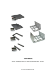
1
USER MANUAL 4BA(N), 4BANA(N), 4BAF(N) , 4BAPZ(N) and 4BAPA(N) SERIES File: 2014-03-20 ER-4BAxx bE0069 GB INSTRUCTION MANUAL 2 _____________________________________________________________________________________________________________________ Table of contents: 1. General description........................................................................................................ 4 2. Meters ........................................................................................................................... 5 3. Completation ................................................................................................................. 7 4. Technical data ............................................................................................................... 7 5. Meter ME-01 balance keys and indicators ................................................................... 10 6. Scale external outputs ................................................................................................. 12 7. Safety principles .......................................................................................................... 14 8. Balance preparation to work ........................................................................................ 15 8.1 Preparing platform, pallet and skid scales ................................................................... 15 8.2 Preparing overrun scales ............................................................................................. 16 8.3 Preparing foundation scales ........................................................................................ 17 8.3.1 Preparing foundation ...................................................................................... 17 8.3.2 Scale installation ............................................................................................ 19 9. Balance start................................................................................................................ 21 10. Operation principles ................................................................................................. 22 11. Balance test ............................................................................................................. 23 12. Accumulator change (ME-01 option) ........................................................................ 23 13. Connection with computer, printer or label printer .................................................... 24 14. Basic function ........................................................................................................... 28 14.1 Normal weighing ................................................................................................... 28 14.2 Weighing with tare ................................................................................................ 29 14.3 Increased readability ............................................................................................. 29 15. Special function description ...................................................................................... 30 15.1 Menu customization function (ACtIV and dEFAUL) .................................................... 31 15.2 Autotare function (AutotAr) ........................................................................................ 32 15.3 Pieces counting (PCS)............................................................................................... 33 15.4 Function for changing mass unit (UnIt) ....................................................................... 34 15.5 Percentage weighing function (PErC) ........................................................................ 35 15.6 Recipe weighing function (RECIPE) .......................................................................... 36 15.7 Function for calibration with external weight (CALIb) .................................................. 37 15.8 Label choosing function (LAbEL) ................................................................................ 39 15.9 Serial port parameters setting (SErIAL) ..................................................................... 40 INSTRUCTION MANUAL 3 _____________________________________________________________________________________________________________________ 15.10 Printout configuration (PrInt) ................................................................................... 41 15.11 Function for weighing large animals (LOC) ............................................................... 43 15.12 Constant tare (tArE) .................................................................................................. 44 15.13 Function for maximum value indication (UP) ............................................................. 46 15.14 Force measuring function (nEWto) ........................................................................... 47 15.15 Anti-disturbance filter function (FILtEr) ..................................................................... 48 15.16 Total weight function (totAL)...................................................................................... 49 15.17 Checkweighing function (thr) ..................................................................................... 51 15.18 Function for setting date and time (dAtE) .................................................................. 54 15.19 Radio communication channel choice function (rF CHn) ........................................... 55 15.20 Entering reference zero function (ZErO).................................................................... 56 15.21 Setting backlight function (b_LIGHt) .......................................................................... 57 15.22 Charging accumulators function (bAttErY)- option..................................................... 58 15.23 Automatic switching off the scale function (AutoOF) ................................................. 59 15.24 Statistical calculations function (StAt) ........................................................................ 60 15.25 Paperweight calculation (PAP) ................................................................................. 63 15.26 Main mass unit change function (lb_bAL) – option .................................................... 64 16. Maintenance and repairs of small defects ..................................................................... 65 Declaration of Conformity.................................................................................................... 66 Appendix A.......................................................................................................................... 68 INSTRUCTION MANUAL 4 _____________________________________________________________________________________________________________________ 1. General description This manual describes scales produces by AXIS Sp. z o.o. and their basic functions. Standard execution scales are equipped with ME-01/A/LED meter and stainless steel scales with ME-01/N/LED. In case of using these meters or special meter for eg. batching meter it is essential to use proper user manual for individual meter type. All balances are tested in respect of metrology. According to order, balances may be verified or calibrated. EC verification (conformity assessment) of balances is required for special applications (trade, tariffs, pharmacy recipes, medical and pharmaceutical analysis, packing of goods). For other applications it is recommended to replace verification with calibration. Verified balances have the following verification features: - protection stamps, located on balance meter and converters connection box (installed under the bearing surface). - Office of Measures marks and green metrological mark, located on the rating plate. Balances classification (PKWiU code) 29.24.23. Certificates: Certificate of type approval no. T7950 ISO Certificate PN-EN ISO 9001:2009 no. AC 090/1141/2245/2011 (AXIS management system) INSTRUCTION MANUAL 5 _____________________________________________________________________________________________________________________ 2. Meters Depending on scale‟s application it can be equipped with following meter: ME-01/A/LED - Standard universal ME-01 meter in aluminium (A) housing and LED display (18mm digits height). Full set of special functions (chapter 15) and standard set of keys. ME-01/A/LCD - Standard universal ME-01 meter in aluminium (A) housing and LCD display (18mm digits height). Full set of special functions (chapter 15) and standard set of keys. ME-01/N/LED – Standard universal ME-01 meter in stainless steel housing and LED display (18mm digits height). Full set of special functions (chapter 15) and standard set of keys. ME-01/N/LCD - Standard universal ME-01 meter in stainless steel housing and LCD display (18mm digits height). Full set of special functions (chapter 15) and standard set of keys. ME-01/N/25 – Universal meter with LED display (25mm digits height) in stainless steel housing. Full set of special functions (chapter 15) and standard set of keys. 6 INSTRUCTION MANUAL _____________________________________________________________________________________________________________________ ME-11/N/LCD (surcharge) – meter with numerical keyboard designed to operate special functions that need inscribing data (e.g. product code, unitary mass), stainless steel housing. ME-02/N/LCD (surcharge) – designed for one-ingredient or multiingredient batching, numerical keys, stainless steel housing. SE-03/N/LCD (surcharge) – designed to cooperate with label printer, numerical keys, stainless steel housing. SE-12/N/2xLCD (surcharge) - designed to operate with computer through RS485 or LAN network, with possibility to connect scanner and label printer (options), 2 displays: digit – weight indication and text - menu and data, stainless steel housing. SE-22/N/2xLCD meter (surcharge) – one-ingredient or multiingredient batching, 2 displays: digit – mass indication and text – recipe ingredients names etc., stainless steel housing. ATTENTION: In order to get acquainted with special functions and other functionality use proper meter user manuals. INSTRUCTION MANUAL 7 _____________________________________________________________________________________________________________________ 3. Completation Basic set includes: 1. 2. 3. 4. The scale RS232C connector (only 4BA/N, 4BA/FN, 4BA/PAN, 4BA/PZN scales) CD with user manuals Warranty 4. Technical data Platform scales 4BA and 4BA/N Scale type Maximum load (Max) Reading graduation (d) Verification graduation (e) Minimum load (Min) Tare set range Precision class Operational temperature Weighing time Platform dimensions: Balance weight: 1000x1000x80(85)mm 60kg 1250x1250x80(85)mm 100kg 1500x1500x80(85)mm 140kg 1500x1500x112(110)mm 150kg 1500x2000x112(110)mm 190kg Display cable length Power supply Internal supply (option) Accumulator working time Indicator protection rating Sensors protection rating 4BA300(N) 300kg 100g 100g 2kg -300kg 4BA600(N) 600kg 200g 200g 4kg -600kg 4BA1500(N) 1500kg 500g 500g 10kg -1500kg 4BA2000(N) 2000kg 1kg 1kg 20kg -2000kg 4BA3000(N) 3000kg 1kg 1kg 20kg -3000kg 4BA6000(N) 6000kg 2kg 2kg 40kg -6000kg III -10†40°C <3s ● ● ● 4m ~230V, 50Hz, 8VA NIMH (size AA) – 4 pcs About 6 h with display backlighting and 16h without 4B – lack of IP 4B/N (stainless scales) - IP65 4B - IP67 4B/N (stainless scales)- IP68 INSTRUCTION MANUAL 8 _____________________________________________________________________________________________________________________ Overrun scales 4BA/NA and 4BA/NAN: Scale type Maximum load (Max) Reading graduation (d) Verification graduation (e) Minimum load (Min) Tare set range Precision class Operational temperature Weighing time Platform dimension (max exter. tread x lenght) Overrun dimensions (szer. x dł. x wysokość) Scale weight Supply Internal supply (option) Accumulator working time Indicator protection rating Sensors protection rating 4BA300NA (N) 300kg 100g 100g 2kg -300kg 4BA600NA (N) 600kg 200g 200g 4kg -600kg 4BA1000NA 4BA1500NA 4BA2000NA (N) (N) (N) 1000kg 1500kg 2000kg 500g 500g 1kg 500g 500g 1kg 10kg 10kg 20kg -1000kg -1500kg -2000kg III -10†40°C <4s 860x1000mm 1000x1250 1250x1500mm mm 1100 x 355 x 50mm 1250x415x50 1500 x 470 x 60mm mm 160kg 250kg 350kg ~230V, 50Hz, 8VA NIMH (size AA) – 4 pcs About 6 h with display backlighting and 16h without 4BA/NA - no IP, 4BA/NAN (stainless scales) - IP65 4BA/NA - IP67, 4BA/NAN (stainless scales)- IP68 Pallet scales 4BA/PA oraz 4BA/PAN: Scale type Maximum load (Max) Reading graduation (d) Verification graduation (e) Minimum load (Min) Tare set range Precision class Operational temperature Weighing time Bearing surface internal dimensions (width.x lenght.x height.) Bearing surface external dimensions (width.x lenght.x height.) Drive (entry) width Display lenght to indicator Supply Internal supply (option) Accumulator working time Scale weight Indicator protection rating Sensors protection rating 4BA300 PA(N) 300kg 0,1kg 0,1kg 2kg -300kg 4BA600 4BA1000 4BA1500 4BA2000 PA(N) PA(N) PA(N) PA(N) 600kg 1000kg 1500kg 2000kg 0,2kg 0,5kg 0,5kg 1kg 0,2kg 0,5kg 0,5kg 1kg 4kg 10kg 10kg 20kg -600kg -1000kg -1500kg -2000kg III -10÷40°C <4s 600x1135x78mm 4BA3000 PA(N) 3000kg 1kg 1kg 20kg -3000kg 840x1260 x78mm 600mm 4m ~230V, 50Hz, 8VA NIMH (AA size) – 4 pcs. About 6 h with display backlighting and 16h without 70kg 4BA/PA - no IP 4BA/PAN (stainless steel) - IP65 4BA/PA - IP67 4BA/PAN (stainless steel)- IP68 INSTRUCTION MANUAL 9 _____________________________________________________________________________________________________________________ Skid scales 4BA/PZ and 4BA/PZN: Scale type Maximum load (Max) Reading graduation (d) Verification graduation (e) Minimum load (Min) Tare set range Precision class Operational temperature Weighing time Skid dim. (width.× lenght.× height.) Wire lenght beetwen skids Wire lenght to meter Supply Internal supply (option) Accumulator working time Scale weight Indicator protection rating 4BA300 PZ(N) 300kg 0,1kg 0,1kg 2kg -300kg 4BA600 PZ(N) 600kg 0,2kg 0,2kg 4kg -600kg 4BA1000 P(N) 1000kg 0,5kg 0,5kg 10kg -1000kg 4BA1500 PZ(N) 1500kg 0,5kg 0,5kg 10kg -1500kg 4BA2000 PZ (N) 2000kg 1kg 1kg 20kg -2000kg 4BA3000 PZ(N) 3000kg 1kg 1kg 20kg -3000kg III -10÷40°C <4s 120×1260×75mm 5m 5m ~230V, 50Hz, 8VA NIMH (AA size) – 4 pcs. About 6 h with display backlighting and 16h without 40kg 4BA/PA - no IP 4BA/PAN (stainless steel) - IP65 4BA/PA - IP67 4BA/PAN (stainless steel)- IP68 Sensors protection rating Foundation scales 4BA/F and 4BA/FN: Balance type Maximum load (Max) Reading graduation (d) Verification graduation (e) Minimum load (Min) Tare set range Precision class Operational temperature Weighing time Foundation depth Platform dimensions: Balance weight: 1000x1000mm 140kg 1250x1250mm 170kg 1500x1500mm 210kg 1500x2000mm 300kg Display cable length Power supply Internal supply (option) Accumulator working time Meter protection rating Sensors protection rating 4BA300F(N) 4BA600F(N) 4BA1500F(N) 300kg 100g 100g 2kg -300kg 600kg 200g 200g 4kg -600kg 1500kg 500g 500g 10kg -1500kg III -10†40°C <3s 28mm ● ● ● ● ● ● ● ● 4BA2000F(N) 4BA3000F(N) 2000kg 1kg 1kg 20kg -2000kg ● ● 4m ~230V, 50Hz, 8VA NIMH (AA size) – 4 pcs. About 6 h with display backlighting and 16h without ME-01/A/18 - no IP, ME-01/N/18 - IP65 IP68 3000kg 1kg 1kg 20kg -3000kg ● ● INSTRUCTION MANUAL 10 _____________________________________________________________________________________________________________________ 5. Meter ME-01 balance keys and indicators Version with LED display: zero stabilization net weight indicator indicator indicator 0 NET Max= metrological data weighing result d= g MAX kg lb MIN unit W1 W2 HOLD TOTAL FUNC PCS scale keys key key key key key key key indicator indicator indicator indicator indicator indicator indicator indicator indicator indicator indicator indicator I/ T 0 MENU HR 0 NET W1 W2 HOLD FUNC PCS g, kg, lb, unit MIN OK MAX - switch-on / switch-off (standby), tare (subtract package weight from weighed mass), zeroing (when the platform is empty), result printout, special function menu, switch: special function/weighing high resolution, zero indicator, result stabilization indicator, - net weight indicator (after using T key ), first range of two-range scale is on, second range of two-range scale is on, indication „hold‟(function LOC and UP), special function on, pieces counting, mass unit indication - weighing result under threshold I, weighing result between threshold I and II, weighing result above threshold II. INSTRUCTION MANUAL 11 _____________________________________________________________________________________________________________________ Version with LCD display: zero stabilization nett mass weighing result indicator indicator indicator Max= metrological data d= bar indicator 0 kg scale keys key key key key key key key indicator indicator indicator indicator indicator indicator indicator indicator indicator indicator indicator indicator indicator indicator indicator indicator indicator indicator I/ T 0 MENU B/G HR 0 NET MODE B/G AUT T TOTAL FILTER, SUM %, ct, n, g/m2, lb,mg PCS n OFF MIN OK MAX BAT , O bar - switch-on / switch-off (standby), tare (subtract package weight from weighed mass), zeroing (when the platform is empty), result printout, special function menu, gross mass indication, high resolution, zero indicator, result stabilization indicator, - net weight indicator (after using T key ), special function on indicator, gross weight (after using TARE function and key), autotare function on, tare memory function on, special functions indicators, - weight result units indications, - pieces counting, measurement quantity indications (total function), turning off the scale by using I/ , weighing result under threshold I, weighing result between threshold I and II, weighing result above threshold II, wskaźnik rozładowania baterii, ACTIV function indicator. scale load indicator (0-100%) INSTRUCTION MANUAL 12 _____________________________________________________________________________________________________________________ Inserting numerical values: 0 - increasing the value of digit, T - dot, - next digit, - end of inscribing. MENU 6. Scale external outputs ME-01 Meter in aluminium housing: RS232C RxD (receive) TxD (transmission) 1 2 3 4 5 mass 6 7 8 RS232C WY Feeder Extensometer 9 housing 12V 1,2A WY (option) P1 (threshold I) P2 (threshold 2) P3 (threshold ) 1 2 3 4 5 housing ground 6 7 8 9 INSTRUCTION MANUAL 13 _____________________________________________________________________________________________________________________ ME-01 meter in stainless steel housing: RS232C 2 RxD (receive) 1 3 9 4 housing 5 Feeder ground 7 8 6 USB option RS232C Extensometer Power unit 12V Ground Separate ground connection (scales in stainless steel version) must be connected using additional conductor. Extensometers are connected permanently. INSTRUCTION MANUAL 14 _____________________________________________________________________________________________________________________ 7. Safety principles It is necessary to become familiar with safety principles shown below, which are necessary to avoid electric shock and damage of balance or connected devices. Repairs and necessary adjustments must be performed by qualified personnel only. To avoid fire hazard, use only typical supply cable, and supply voltage must be consistent with technical data. For the balance supply use the socket with protective contact. Do not use balance when the cover is removed. Do not use balance in explosive atmosphere. Do not use balance in locations with high humidity, when the cover does not have special protections for N type. In case of damage suspicion, switch the balance off and do not use it until it is tested in professional service company. According to valid regulations regarding natural environment protection do not place used electronic devices in containers with common waste. Used balance after operation period may be transferred to units authorized for collection of used electronic equipment, or to place of purchase. INSTRUCTION MANUAL 15 _____________________________________________________________________________________________________________________ 8. Balance preparation to work 8.1 Preparing platform, pallet and skid scales 1. Unpack balance, remove protective foils. 2. Place balance on flat, horizontal foundation, in place not subjected to mechanical vibrations and strong air movements. 3. Air bubble in level should be located in the middle position. Good Bad 4. Attach meter to the wall, desktop or tripod (option), choosing one of three methods. 5. Connect the supply cable plug to socket with protective contact, when balance is unloaded. INSTRUCTION MANUAL 16 _____________________________________________________________________________________________________________________ 8.2 Preparing overrun scales 1. Unpack balance, removing protective foils. 2. Place balance on flat, horizontal foundation, in place not subjected to mechanical vibrations and strong air movements. Take care if the scale stays on all four legs. 3. Air bubble in level should be located in the middle position. Good Bad 4. Lift scale corners up and put locks under in such way that scale legs go into prepared holes. 5. Mount locks permanently to the ground using 10 holes. 6. Put balance approaches (drives) on settling them into locks. 7. Unscrew transport). transport handles (mounted for 8. In hermetic scales plug not used joints with supplied caps. Attach meter to the wall, desktop or tripod (option), choosing one of three methods. 9. Connect the supply cable plug to socket with protective contact, when balance is unloaded. INSTRUCTION MANUAL 17 _____________________________________________________________________________________________________________________ 8.3 Preparing foundation scales 8.3.1 Preparing foundation CAUTION! Decision of substrate reinforcing and density is taken by building works designer. All dimensions are in millimetres. 1. 2. 3. 4. 5. 6. During foundation preparation follow the principles below: Foundation and feet under balance legs should be made from concrete. Foundation bottom thickness should not be smaller than 100 mm. Foundation bottom inclination angle (shown in fig. 1 on page 8) should be at least 3%. Keep the same level for all feet. Level the foundation frame, keeping perpendicularity of sides and equality of diagonals. Diameter of PVC pipe for cables to connection box should be at least 50 mm. Keep the area free from reinforcing bars as shown in fig. 2 on page 8. 7. Foundation external and internal dimensions, proper for various platform dimensions are shown in table below. Balance type Platform dimensions [mm] 4B300FN 4B300FN 4B300FN 4B600FN 4B600FN 4B600FN 4B1500FN 4B1500FN 4B2000FN 4B2000FN 4B3000FN 4B3000FN 800x800 1000x1000 1250x1250 800x800 1000x1000 1250x1250 1250x1250 1500x1500 1250x1250 1500x1500 1500x1500 1500x2000 Foundation internal dimensions (WxLxH) [mm] 820x820x128 1020x1020x128 1270x1270x128 820x820x128 1020x1020x128 1270x1270x128 1270x1270x128 1520x1520x128 1270x1270x128 1520x1520x128 1520x1520x128 1520x2020x128 Foundation enternal dimensions (WxL) [mm] 1220x1220 1420x1420 1670x1670 1220x1220 1420x1420 1670x1670 1670x1670 1920x1920 1670x1670 1920x1920 1920x1920 1920x2420 Keep all dimensions, shown in drawings and table. Careless and inaccurate foundation preparation may make balance installation impossible or cause its improper operation! INSTRUCTION MANUAL 18 _____________________________________________________________________________________________________________________ Foundation frame with anchors Rama fundamentu z kotwami 200 60 Feet under Stopy podbalance nóżkilegs wagi Kolektor doWater odprowadzenia wody collector Rura z PCV PCV pipe cable na for przewód Fig.1 Foundation – crosssection Places for frame anchors Miejsca na kotwy ramy Obszar wolny Area od prętów reinforcement zbrojeniowych bar free 210 180 65 210 180 65 70 300 300 Fig. 2 Foundation – view from above Rama fundamentu Foundation zframe kotwami with anchors INSTRUCTION MANUAL 19 _____________________________________________________________________________________________________________________ 8.3.2 Scale installation 1. Balance structure 1 2 3 4 5 2. Screws fixing the limiter 3. Screws fixing base plates 4. Limiter 5. Base plate 6. Foundation 7. Balance leg 6 7 1. 2. 3. 4. 5. 6. 7. 8. 9. 10. 11. 12. 13. 14. Prepare the foundation (7) according to guidelines (section 6) and engineering technique principles. Put the balances base plates (5) freely in the foundation. Place limiters plates (4) on plates (5). Connect both plates with M8 screws (2) so they cannot move in respect to each other, but to allow for limiters (4) manoeuvring. Unscrew screws fixing the balance upper plate. Put the balance structure (1) in the foundation, so legs (7) fit vertically in the limiters (4) holes. Place upper plate on balance structure and lightly screw in the fixing screws. Check the upper plate location in the foundation – level in relation to foundation edge and distance from the edges (fig. 1). When needed, shift the plates (5) or put spacers beneath them, made from sheet with dimensions of plate. If the position of upper plate is correct, carefully remove it to not move plates (5). Check if legs (7) are straight. Carefully remove balance structure (1) from foundation to not move plates (5). Fix plates (5) with supplied screws with steel pins. Adjust possible displacements with plates (4) position, so legs are located centrally and vertically in plates (4) holes. Tightly screw plates (5) and (4). Put balance structure (1) in place. Place the upper plate and fix it with screws, beginning from holes in the upper plate centre. Connecting cable must be laid freely! 20 INSTRUCTION MANUAL _____________________________________________________________________________________________________________________ 15. Unpack the balance. Attach meter to the wall or desktop, choosing one of three methods. 16. Connect the supply cable plug to socket with protective contact with unloaded balance, which will cause autotests performing and after indication stabilization displaying of sero indication INSTRUCTION MANUAL 21 _____________________________________________________________________________________________________________________ 9. Balance start Connecting of supply plug to socket of ~230V/50Hz installation with unloaded balance will cause the following sequence of actions: Display test Tests of basic electronic subassemblies, ended with messages: C1, C-2, ... C-6. Displaying of meter type Displaying of software version. Ready for operation. 22 INSTRUCTION MANUAL _____________________________________________________________________________________________________________________ 10. Operation principles 1. Before each measurement the balance should be properly zeroed, which is signalled by “” indicator. If the zero indication is not shown when the balance is unloaded, or "----" is displayed, press the "" key. 2. The balance enables tare setting in the whole measuring range. It is performed by pressing "T" key. 3. Weighed mass should be placed in the platform centre. Do not drop weighed objects on the platform. Do not overload the balance over 20% of maximum load. 4. The weighing result should be read during the " stabilization. " indicator lighting, which indicates the result 5. When there is no weighing, but the balance should be ready for operation, it may be switched off by I/ key. It causes the balance reading system deactivation end entering the standby mode. Balance turning on is performed by pressing " I/ " key. 6. Protect the balance from dust, aggressive dusts and liquids. For cleaning purposes use water and dry it. INSTRUCTION MANUAL 23 _____________________________________________________________________________________________________________________ 11. Balance test During balance operation, in order to confirm its efficiency, it is recommended to check the weighing precision by putting and object of exactly known weight before and after series of measurements. For testing of verified balances use weight standard, having valid standardization certificates. In case of allowable measurement error exceeding contact authorized service company to perform balance adjustment. Balance adjustment must be performed by authorized service company only, as it is connected with necessity of seals breaching, required for warranty purposes. 12. Accumulator change (ME-01 option) 11 12 13 1. Remove screws 11 holding plate 12, remove the plate. RS232C WY Tensometr Extensometer 12V 1,2A 2. Take out container with accumulators 13 and place 4 AA format accumulators. The way of packing accumulators into the container is shown on the figure on the left and is also shown on the container. INSTRUCTION MANUAL 24 _____________________________________________________________________________________________________________________ 13. Connection with computer, printer or label printer The scale is equipped with RS232C, which can be used to connect external devices such as computer or a printer. RS232C 1 RxD (receive) TxD (transmission) 2 3 4 GND 5 6 7 8 9 +5V(option) When cooperating with computer, the scale sends weighing result after initialize signal from computer or after pressing key on the scale. When cooperating with a printer data is send automatically after result stabilisation, but next transmission is possible after removing previously weighted sample. housing When cooperating with label printer after pressing key, the scale sends instructions set for the label printer. Label number 0001, hour, data (if the clock is installed and on) and nett weight. During transmission LabEL communicate is displayed. The way of sending data and transmission parameters is set using SErIAL special function. Set of send data is set using special function PrInt. The following data can be send: - Header (scale type, Max, d, e, serial number), Operator identification number, Successive printout number (measurement), Identification number or product bar code, Number of pcs (PCS function only), Single detail mass (PCS function only), Nett weight, Tare (package mass), Gross weight, Total mass (Total function only). If the scale is equipped with two serial joints Print function is set independently for both interfaces. Computer must have a special program for cooperation with data from a scale. Dedicated programs are also offered by AXIS. Except RS232C joint, the scale can be equipped with USB or Wi-Fi interface. Needed controllers and instruction can be found on a CD supplied with Axis scales . INSTRUCTION MANUAL 25 _____________________________________________________________________________________________________________________ Detailed protocol description LonG protocol Communication parameters: 8 bits, 1 stop bit, no parity, baud rate 4800bps, initialising signal (data send order) – correspond to press key ComputerScale: S I CR LF (53h 49h 0Dh 0Ah), ScaleComputer: scale response according to description below (16 bytes): Byte Byte Byte Byte Byte Byte Byte Byte Byte Byte Byte 1 2 34 5÷9 10 11 12 13 14 15 16 - sign „-” or space space digit or space digit, decimal point or space digit space k, l, c, p or space g, b, t, c or % space CR LF Attention: Network number different than zero (Port/nr function) changes scale working mode: communication with a computer is possible after logging the scale in with 02h scale number command. To log the scale out use 03h command. For example: Using a program to test RS232 interface ( program is available in www.axis.pl / programy komputerowe ) for scale number 1 please write: $0201 to log in, then SI, and write: $03 to close communication. Asking about scale presence in system (testing scale connection with computer): ComputerScale: S J CR LF (53h 4Ah 0Dh 0Ah), ScaleComputer: M J CR LF (4Dh 4Ah 0Dh 0Ah), Displaying a inscription on scale‟s display (text communicate from computer): ComputerScale: S N n n X X X X X X CR LF, nn-displaying time in seconds; XXXXXX-6 signs to display ScaleComputer: M N CR LF (4Dh 4Eh 0Dh 0Ah), Scale tarring (calling T key press) : ComputerScale: S T CR LF (53h 54h 0Dh 0Ah), ScaleComputer: without response, Scale zeroing (calling 0 key press): Computer Scale: S Z CR LF (53h 5Ah 0Dh 0Ah), Scale Computer: without response, Scale turning on / off (calling I/ key press): Computer Scale: S S CR LF (53h 53h 0Dh 0Ah), Scale Computer: without response, INSTRUCTION MANUAL 26 _____________________________________________________________________________________________________________________ Entering to special function menu (calling MENU key press): Computer Scale: S F CR LF (53h 46h 0Dh 0Ah), Scale Computer: without response, Setting low threshold value (option): Computer Scale: S L D1...DN CR LF (53h 4Ch D1...DN 0Dh 0Ah) D1...DN – threshold value, maximum 8 characters („-” – negative value, digits, dot – decimal separator), number of digits after dot should be the same as on scale display, Scale Computer: without response, Example: in order to set low threshold 1000g in scale B1.5 (d=0.5g) the following order should be sent: S L 1 0 0 0 . 0 CR LF (53h 4Ch 31h 30h 30h 30h 2Eh 30h 0Dh 0Ah), in order to set low threshold 100kg in scale B150 (d=50g) the following order should be sent: S L 1 0 0 . 0 0 CR LF (53h 4Ch 31h 30h 30h 2Eh 30h 30h 0Dh 0Ah),), Setting high threshold value (option): Computer Scale: S H D1...DN CR LF (53h 48h D1...DN 0Dh 0Ah), D1...DN – threshold value (see ) Scale Computer: without response. Connecting cable WK-1 (scale – computer / 9-pin interface): SCALE COMPUTER Connection cable WD-1 (connects scale with AXIS printer): SCALE KAFKA PRINTER Setting of internal switches of AXIS printer: SW-1 on SW-2 off SW-3 SW-4 SW-5 SW-6 SW-7 SW-8 on off off on off off INSTRUCTION MANUAL 27 _____________________________________________________________________________________________________________________ ELtron protocol Transmission parameters: 8 bits, 1 stop bit, no parity, baud rate 9600bps, After using key in scale: ScaleLabel printer : set of instruction in EPL-2 language that initialize label printing: US FR"0001" ? mm:gg rrrr.mm.dd masa P1 - Steering instruction Label number define instruction Instruction that starts list of variable signs 5 signs: minutes:hour 10 signs: year.month.day 10 signs: scale indication+ mass unit Steering instruction Attention: 1. Except variable signs constant signs also can be inscribed for example factory name, product name and so on. 2. In standard one label pattern is possible to prinout (number 0001). Using bigger amount of patterns (other label numbers) is possible thanks to LAbEL special function. 3. To achieve label printout, label printer must have inscribed label pattern (label pattern is created on computer and using computer it is saved to label printer memory). Label pattern is designed by ZEBRA DESIGNER program which is supplied together with label printer. 4. Scales parameters and transmission protocol must corespond to label printer type. INSTRUCTION MANUAL 28 _____________________________________________________________________________________________________________________ 14. Basic function To make clear how to manage with each function, in further part of instruction descriptions are replaced with pictures. - put a load on the pan - remove the load from the pan 2.30 - press the key when indication is displayed T - forced change - automatic change 14.1 Normal weighing 0.00 2.30 0 Press key (T key in non-legalized scales), which zeros the scale, operates only when the pan is empty . Weighing result should be read when the indicator " " lights. INSTRUCTION MANUAL 29 _____________________________________________________________________________________________________________________ 14.2 Weighing with tare 2.30 NET 0.00 T The scale is equipped with tare equal to its range. Joint value tare and mass net can not cross a maximum of scale. To display gross weight press B/G key. NET 40.01 Note: Press B/G key to return to net weight indication. 42.31 14.3 Increased readability 2.30 2.29 2.30 Press HR key to display the weighing result (for 5s.) with the highest readability possible. This function is especially helpful in scales with legal verification with d=e. The weighing result with increased readability can be used for informational purposes only and cannot be printed or sent to a computer with key. INSTRUCTION MANUAL 30 _____________________________________________________________________________________________________________________ 15. Special function description All scales besides basic metrological functions: weighing and taring, have a set of special functions. Depending on meter type functions set differs. Below a list of functions available in standard ME-01 type meters: menu customization function (ACtIV), removal of all function from menu (dEFAUL). autozeroing function (AutotAr), pieces counting function (PCS), change of mass unit (UnIt), percentage weighing function (PErC), recipe weighing function (rECIPE), extended calibration function (CALIb), selecting label number function (LabEL), function for setting serial port working (PrInt), function for setting serial port (SErIAL), weighing large animals function (LOC), entering tare function (tArE), maximum value indication function (UP) force measuring function (nEWto) anti-disturbance filter function (FILtEr) entering reference zero (ZErO) setting backlight (b-LIGht) – only for scales with LCD statistical calculations (StAt) paperweight calculation function (PAPEr) main mass unit change (lb_bAL) - option and functions that require additional equipment to be completely functional: option with accumulator supply: - Setting accumulators charging (bAttErY) - Automatic switching off scale function (AutoOFF) options with the clock: - setting current date and time function (dAtE) - total weight function (totAL) options with the transoptors connectors: - checkweighing function (thr) option with USB: - function for setting additional serial port (SErIAL/Port-2) option with radio connection: - function of choosing communication channel (rF Chn) User creates his own menu by activating functions in ACtIV function (described in chapter 15.1). In scales with LCD display some special functions have additional marks on display and names of some functions are extended. INSTRUCTION MANUAL 31 _____________________________________________________________________________________________________________________ 15.1 Menu customization function (ACtIV and dEFAUL) Among available user functions it is possible to select these, which should be displayed after pressing MENU key. It allows avoiding displaying whole list of available functions, which makes operation time longer. 0.00 ACtIV T . AUtOtA After switching on ACTIV function a dot is displayed on the right side (to distinguish from regular menu). Chosen functions are displayed with a dot on the left side. Operation sequence shown in the pictures on the left causes adding function for setting serial interface RS232C parameters (Port) to function menu. . PCS .PCS oFF PCS on T In every moment, it is possible to restore primary (manufacture) settings choosing dEFAULt special function. In order to remove function from menu in the last operation in place of selecting PCS on choose PCS oFF. T INSTRUCTION MANUAL 32 _____________________________________________________________________________________________________________________ 15.2 Autotare function (AutotAr) 0.01 AutotA MENU T Note: 1. AUt sign occurs only in scales with LCD display. 2. In scales with 0 key active function changes name into AutoZE (autozeroing) and works only when the scales is unbiased. Aut oFF Aut on AUT 0.00 When the function is activated, the scale automatically ensures stable zero indication if the pan is empty or if zero indication was acquired by pressing T key. To leave the function press MENU key, then with T key chose AutotA and Aut oFF. T INSTRUCTION MANUAL 33 _____________________________________________________________________________________________________________________ 15.3 Pieces counting (PCS) 0.00 T 5 23.40 PCS T PCS oFF PCS on T PCS .. PCS 5 WAIt 12 . 5 . 0 . 12 T This function enables to count identical pieces, e.g. turnbuckles or buttons. A measurement is performed in two phases: - first phase - single piece weight calculation on the basis of defined pieces amount (5, 10, 20, 50, 100, 200 or 500 pieces), - second phase – pieces counting. First phase options: - PCS . . – recalling of a value inserted earlier (this quantity must be inscribed earlier), -PCS SEt – set any amount of pieces in a sample, -PCS uM – set unitary mass directly, -PCS rS – inserting number of details in a sample and receiving of their mass from other scale connected by RS-232C. It is advised that single piece weight is not less than one reading unit and sample weight used in first phase is bigger than 100 reading units. To leave function press MENU key and then using T key chose PCS and PCS oFF. Note: 1. PCS Err communicate signalises that a sample was not put on the pan or if single piece weight is less than one reading unit (it is possible to count pieces but measuring error is bigger). 4.In scales equipped with LCD display, weighing unit is visible and "" sign is replaced with "pcs ". INSTRUCTION MANUAL 34 _____________________________________________________________________________________________________________________ 15.4 Function for changing mass unit (UnIt) 1.60g MENU UnIt T CArAt T 8.00 ct - The function allows selecting weighing unit: CarAt (1 ct= 0,2 g) - carat, MGrAM (1mg=0,001g) milligram, KGrAM (1kg=1000g) kilogram, Pound (1 lb=453,592374g) English pound, OunCE (1oz=28,349523g) - ounce, OunCEt(1ozt=31,1034763g) pharmaceutical ounce, GrAIn (1gr=0,06479891g) - grain PennYW (1dwt=1,55517384g) jewellery mass unit, GrAM (1g) - gram. The way of choosing carats as weighing unit is shown on the example. Attention: In scale with LCD, sign "■" is replaced by designations of mass units: lb, kg, oz, ozt, ct. INSTRUCTION MANUAL 35 _____________________________________________________________________________________________________________________ 15.5 Percentage weighing function (PErC) 100% This function allows displaying weighing result in percents. 0.00 A measurement is performed in two phases: 19.00 PErC MENU 50% sample - second phase – measuring specific sample as a percentage of the reference sample. T Weighing result is displayed in different format, depending on the weight value of reference sample. For weight values of reference sample 0†3,5% of weighing range result is displayed in format 100, for range 3,5†35% - in format 100.0, and above 35% - in format 100.00. T The function has the following options: - PEr oFF – disable the function, - PEr on– set current scale indication as 100% and activate percentage weighing, -out- exit without changing settings. PEr oFF PEr on - first phase – weighing a reference (100%), .100.00 . 50.00 Note: 1. PEr Err 2. In scales with LCD display sign "■" is replaced with %. INSTRUCTION MANUAL 36 _____________________________________________________________________________________________________________________ 15.6 Recipe weighing function (RECIPE) 0.00 rECIPE A rEC on T T The function has the following options: - rEC oFF – leave the function with possibility of reading to read total weight, -rEC Con – continue previous recipe. When preparing a recipe successive ingredients (A, B, C, etc.) are weighed each time starting from zero indication. In order to allow this after weighing of each ingredient tare the scale. 0.00 0.12 C T - rEC on – start recipe weighing 0.11 B MENU This function allows for separate weighing of several ingredients in one container with a possibility of control total weight of all weighed components. T 0.00 After weighing of several ingredients reading total weight is possible (despite scale taring). In order to do that press MENU key, select rECIPE function once more and use rEC oFF option. Sign „” signals total weight indication. Recipe is finished when T key is pressed. 0.13 T 0.00 MENU When „” sign is displayed recipe continuing is possible. rEC Con option is used for that. Note: A+B+C rECIPE T rEC oFF T __ _ 0.36 T Sign „” on the left side of display informs about rECIPE function activity. INSTRUCTION MANUAL 37 _____________________________________________________________________________________________________________________ 15.7 Function for calibration with external weight (CALIb) Calibration with external weight should be performed if scale accuracy is not satisfactory. Calibration weight stated in technical data table for the scale (or of better accuracy) should be used then. Operations sequence: Press MENU key to display user functions, shown one by one in loop. 0.00 Press T key when CALIb function appears. CALIb T CAL on ... CAL StP T m T -CAL- The following options will be displayed: -CAL on – calibration with external recommended value weight (see technical data). -CAL StP – calibration with external weight, confirmation of next steps - MENU key, out – leave without changes Press T key when CAL StP option appears (calibration in two steps). Press MENU and wait for writing zero to the scale. When LOAD message appears put standard of mass on the pan. Press MENU key (CAL on doesn‟t need pressing MENU key). PrESS MEnU Wait until internal calibration is finished and zero indication is displayed. m PrESS MEnU m INSTRUCTION MANUAL 38 _____________________________________________________________________________________________________________________ Sequence of actions during calibration with chosen value of standard of mass: 0.00 CALIb CAL StP Press MENU key to display user functions. T Press T key during displaying CALIb. Press T key during displaying CAL StP. T Following options will be displayed: -Pt on – calibration with chosen mass value, m othEr T -Pt StP – calibration with chosen mass value with confirmation of successive steps using MENU key, out – out of calibration. SEt CAL Press T key during displaying othEr. Using keys inscribe values of standard of mass: _ 0 1 T 10 0 m -CAL- 0 - increasing digit, - dot, T - next digit, MENU - end of inscribing. Further calibration process instructions are made analogically as mentioned on previous side. INSTRUCTION MANUAL 39 _____________________________________________________________________________________________________________________ 15.8 Label choosing function (LAbEL) This function is used in scale with ELTRON (SErIAL function) data protocol. This protocol enables label printout with actual scale indication and chosen data from PrInt special function (variable data), for example date and time. Other data, for example company address, product name, barcode can appear on label as a constant text. Label patterns with number (4 digit) used by user should be saved in scale memory according to printer manual. Label pattern choice is made by inscribing label number using LAbEL function. Press MENU button. When LAbEL is displayed press T key. Actual label number will show. To enter new label number press T key, to exit function without number change press MENU. 5.00 LAbEL T To inscribe label number use keys: 0 - digit increase, 1 T T - next digit, MENU – end. - 2 20 ... After entering label number, putting load and pressing key will cause sending data to label printer. T ... Data format sent to label printer (label nr 1, language EPL-2): 27 5.00 US FR"0001" ? 00:00 2000.00.00 10 g P1 (55 53 0D 0A) (46 52 22 30 30 30 31 22 0D 0A) (3F 0D 0A) (30 30 3A 30 30 0D 0A) (32 30 30 30 2E 30 30 2E 30 30 0D 0A) (20 20 20 20 20 31 30 20 20 67 0D 0A) (50 31 0D 0A) INSTRUCTION MANUAL 40 _____________________________________________________________________________________________________________________ 15.9 Serial port parameters setting (SErIAL) 0.00g MENU The function allows setting the following communication parameters of serial interface: - transfer protocol (Prot): SErIAL T LonG – printer, computer Eltron – label printer baud T -4800 - baud rate (bAud): (4800, 9600, 19200, 38400, 57600bps), - number of bits in single char. (bitS): 7, 8, - parity control (PArItY): nonE – no control Odd –nonparity -9600 T Even – parity control, - scale number in network (nr): baud (if the scale doesn’t work in network the number must be 0), ... out 0.00g T - result transmission kind through serial interface (SendInG) : stb – transmission after key is used and result is stable, – transmission after need of stabilisation, key is pressed without - automatic transmission after load is put on and result is stable (Auto), - continuous transmission, about 10 results per second (Cont.) Default parameter values: Long, 9600 bps, 8 bits, none, stb In order to set needed parameters choose Port-1 function, select appropriate parameter and press key when required option or parameter value is displayed. The way of setting baud rate of 9600 bps is shown as example in the pictures on the left, setting other parameters is performed similarly. In scales with an additional serial port appear Port-1 and Port-2, for the independent setting of both ports. INSTRUCTION MANUAL 41 _____________________________________________________________________________________________________________________ 15.10 Printout configuration (PrInt) Function is used for printing additional information stored in scale memory, weighed product identification data and scale operator inscribed using scale keys and scanner. 0.00 The function allows switch on/off the following positions on printout: PrInt T HEAdEr T On T totAL T On T out T - HEAdEr – header: name, model and scale number, - Id OPEr – operator code (max 6 digits), - Prn no – successive printout number (choose this option to zero counter), - Id Prod – product number (13 digits), - Count – counting result, - totAL – result sum, - APW – unitary mass, - netto – net mass - tArE – current tare value, - brutto – gross mass - totAL – total mass (totAL function) If Id Prod or Id OPEr is chosen, it is possible to inscribe quickly their new values (with omission of main menu). In order to do that hold (about 3 seconds) MENU key and release when Id Prod or Id OPEr indicates. Inscribe new value using keys: 0 - increasing digit, - decimal point, T - next digit, MENU - end. While inscribing Id Prod user can use scanner connected to RS232C interface. 0.00 If the scale is equipped with two serial joints after choosing Print function user can independently configure both interfaces Port-1 and Port-2. INSTRUCTION MANUAL 42 _____________________________________________________________________________________________________________________ Sample printout during normal weighing (all printout positions deactivated): 20.07 kg 20.04 kg 20.04 kg Sample printout during normal weighing with clock option (all printout positions deactivated): 20.07 kg 2012-11-08 10:01 20.04 kg 2012-11-08 10:01 20.04 kg 2012-11-08 10:01 Sample printout during normal weighing (all printout positions activated): BA30 MAX: 30kg e=d=0.01kg S/N : ID OPER. DATE TIME NO ID PROD. COUNT APW NET TARE GROSS TOTAL : 000001 : 2012-11-08 : 12:26 : 3 : 01 : 0 PCS : 0.000 g : 3.08 kg : 0.00 kg : 3.08 kg : 0.00 kg INSTRUCTION MANUAL 43 _____________________________________________________________________________________________________________________ 15.11 Function for weighing large animals (LOC) The function allows weighing animal moving on the scale. 0.00 LOC MENU Press MENU key. T LOC oFF LOC on . 0.00 LOC T When LOC function is displayed press T key. The following options appear on display successively: - LOC oFF – leave the function, - LOC on – automatic weighing after loading the scale, - LOC Prn – the measurement initiated manually by pressing key. When LOC on is displayed press T key. Tare the scale using T key if necessary and place the animal on the pan. Wait until the weighing result is averaged – scale display will be blinking. Then scale will show stable averaged result and will send it through serial port. Final result is displayed on the display and send via serial port to computer or printer. The result remains on display for about 30 second. 0.25 PrInt . 0.25 Important notes: 1. The loads less than Min are not averaged. 2. In the case when placing the animal takes more than 5s, it is advised to use LOC Prn (measurement initiated manually). It will allow performing measurement in right moment pressing key. INSTRUCTION MANUAL 44 _____________________________________________________________________________________________________________________ 15.12 Constant tare (tArE) This function enables to measure gross weight of a sample placed in a container of a known weigh value (stored in the memory) and to display calculated net weight of the sample. Tare value is recalled from the memory with 0 or T key when the pan is empty. Tare value may be entered using the keypad or by sampling container weight from the pan. Operation sequence: The following options are possible: - tAr 0FF – leave the function, - tAr on – activate the function with the previous tare value, - tAr .. – sample tare value from the pan, - tAr SEt– enter tare value with keys: 0, , T and MENU out – printout a setting value of tare. 37g tArE T tAr SEt T tArE 01 T MAnUAL T 3 30 37 0g Press T key during tAr Set displaying. By pressing T key choose proper memory cell where tare will be stored: tAr 01, 02, ... , 10. Choose inscribing method : - MAnUAL – inscribing using keys: 0, , T and MENU, - Pan – inscribing mass value that is on the pan. ... After storing tare, the scale starts working with inscribed tare value. T ... Note: Tare value is stored in memory also after unplugging the scale from the mains. INSTRUCTION MANUAL 45 _____________________________________________________________________________________________________________________ Weighing with constant tare: 0g In order to use tare value that is located in memory, choose from menu tArE function and then tAr on option. A list of memory cells will show up: tAr 01, 02, ... , 10. Cells with inscribed value are marked with "■" sign. tArE T tAr on T . tArE 01 ATTENTION: In scales with LCD display, cells with inscribed value are marked with o sign on the left side. Active value is marked with sign. T Choose proper memory cell using T key. -3g 3g 0g 50g 50g tArE function is activated with chosen tare value. Moreover the scale will indicate nett weight (weight on the pan minus tare values). Using T key (or0, while empty pan) causes scale zeroing and then substraction of recalled tare. Minus indication will show up. INSTRUCTION MANUAL 46 _____________________________________________________________________________________________________________________ 15.13 Function for maximum value indication (UP) This function allows holding maximum (or minimum) value indication shown by the scale at the moment. 0.00 MENU Before measurement scale should be tared. Function has following options: UP T UP oFF HIGH 1.00 1g 1g 10.00 10.00 T -UP oFF – function off, -HIGH – holding maximum value, -LOW – holding minimum value. Pressing T key will cause result zeroing. Note: Autozeroing function and the stabilisation indicator are deactivated when UP function is running. Weighing result is continuously averaged from 5 measurements. INSTRUCTION MANUAL 47 _____________________________________________________________________________________________________________________ 15.14 Force measuring function (nEWto) 0.00 Function activation causes displaying result in force units (N). Press MENU key. nEWto T Attention: Units converting from mass (kg) to force (N) is made for acceleration of gravity (g=9,80665m/s2) nW oF nW on 0.000 Using T key choose NEWto function, and then NW on. Note: 1N 0,1019kg T INSTRUCTION MANUAL 48 _____________________________________________________________________________________________________________________ 15.15 Anti-disturbance filter function (FILtEr) 0.00 MENU FILtEr T FIL oFF FIL 10 FIL 20 FIL 40 0.00 T This function allows using digital filter with selected intensivity during weighing. Filter reduces the influence of mechanical vibrations (air blasts, base vibrations) on measurement result. Press MENU key and select FILtEr by pressing T key. The following options will be shown successively on display: - FIL oFF – work without filter, - FIL 10 - filter I (weak), - FIL 20 - filter II (medium), - FIL 30 - filter III (sharp), - FIL 40 - filter IV (very sharp). Select on of four filters. This will cause starting weighing with selected filter. In order to return to normal scale work use MENU key and choose FIL oFF. INSTRUCTION MANUAL 49 _____________________________________________________________________________________________________________________ 15.16 Total weight function (totAL) The function allows calculating total weight for series of measurements, which can be greater than scale capacity. It allows calculating total weight as well as average value. 0.00 MENU totAL T tot q T 10.00 n MENU totAL T tot Prn T 2 _ _ 15.00 0.00 key for In order to print and display results enter the function by choosing totAL and tot Prn option from menu. 20.00 __ _ 30.00 The following options will appear successively: - tot Prn - report printout without clearing total register, - tot oFF - clearing total register, report printout and leaving the function, - tot - working with receipt printout after each measurement, - tot - working without receipt printout, - tot CFG – saving measurement mode (using key: Manual, after taking off the load : auto). Press T key when tot is displayed. Perform measurement series by pressing storing results into total register. 0.00 0.00 Press MENU key. When totAL is displayed press T key. The results are display in the following sequence: - total weight () - number of registered measurements (n), - average value (=), regarding that moving to display successive result is performed after pressing key. In order to go back to total weighing without zeroing total register press key third time. 50 INSTRUCTION MANUAL _____________________________________________________________________________________________________________________ To leave the function with clearing total register, select totAL function from menu and choose tot oFF option. When It will cause the scale prints the communicate informing about clearing registers. The form of receipt after each measurement: Date: ... Time. ... measurement no weight measurement no weight Report form: Date: ... Time. TOTAL WEIGHT NUMBER OF SAMPLES AVERAGE VALUE ... = = = Note: When the scale doesn’t have an internal clock, Date and Time do not appear on printout. Maximum number of measurements is 99 999. Maximum total load 99 999 000d. The weighing unit of the total value from the register (Total) is the same as the weighing unit stated on the keypad or is 1000 times greater, what is signalled by “o” indicator at the left of the display. If the registered value is too big to be displayed, “E” communicate appears on the display. If the number of series is too high and cannot be displayed, “Err1”communicate appears on the display. INSTRUCTION MANUAL 51 _____________________________________________________________________________________________________________________ 15.17 Checkweighing function (thr) This function allows comparing weighing result with two programmed reference values: lower and upper threshold. Comparison result is signalled with indicators (MIN, OK, MAX) and sound signal generated when threshold values are exceeded. If comparison result is: - smaller than lower threshold – the scale signals MIN (yellow colour), - between threshold values - the scale signals OK (green colour, with the short sound signal), - greater than upper threshold - the scale signals MAX (red colour, long sound signal). The checkweighing results can be use to control: - optical indicator (Indication mode), - batching devices (Batching mode). Standard scale is set for cooperation with optical indicator. On outputs P1-P3 (Relays socket) short-circuit states appear as result of comparison scale indication with threshold values. On the chart below output states are shown during increasing load on the scale for both working modes: Indication mode: Batching mode: P1 P1 zero treshold thr I thr I P2 P2 thr I thr II P3 thr II P3 thr II zero treshold In Batching mode on P1 (thr I) and P2 (thr II) outputs short-circuit impulses appears for time of 0,5s. On P3 (zero) output short-circuit state appears when indication does not exceed threshold value signalling zero load. 52 INSTRUCTION MANUAL _____________________________________________________________________________________________________________________ Relays connection diagram: Imax < 25mA Relays output is the open collector transoptor output with load capacity 25mA / 24V. Transmitter inputs must be protected with diodes, e.g. 1N4148. It is advised to use MS3K/P electronic board (sold separately), consisting of RM96P transmitters, with DC24V input voltage and AC250V, 3A output. Important notes: 1. After switching the scale on, both thresholds are set to maximum values. 2. When setting upper threshold value, pay attention that its value is not below lower threshold value. 3. Setting lower and upper threshold value is possible after sending appropriate orders from computer, what is described in scale user manual. INSTRUCTION MANUAL 53 _____________________________________________________________________________________________________________________ Operation sequence: 0.00 MENU thr T thr on T SEt-1 T 0 5 550 SEt-2 100 SEt-3 5 SEt-0 62.00 T 0 MENU T MENU T MENU T Press MENU key and choose thr pressing T key. The following options are displayed successively: - thr oFF – deactivate the function, - thr on – activate the function, - thr Prn – check last threshold values (press key several times), - thr CFG – choose Relays socket mode: 0 – exit to weighing 1 – Batching mode 2 – Indication mode. Choose thr-on option using T key. The following options for entering thresholds are displayed: - SEt-0 - go to weighing with signalling threshold excess, - SEt-1 - set lower threshold value, - SEt-2 - set upper threshold value, - SEt-3 - set zero signalisation threshold. Using T key select SEt-1 option. Set lower threshold value using the following keys: 0 - digit increase, - decimal point, T - move to next digit, MENU - finish. Then select SEt-2 option and enter upper threshold value. Choosing SEt-0 option will cause starting work with signalisation of exceeding thresholds and zero. To change Relays socket mode use thr CFG option. Default option is Indication. To leave the function, press MENU key and then choose thr and thr oFF options. INSTRUCTION MANUAL 54 _____________________________________________________________________________________________________________________ 15.18 Function for setting date and time (dAtE) 0.00 dAtE MENU T dAt oFF dAt on T T h13 - 18 0 h13 - 19 T Attention: Inscribing non-zero PIN value causes showing PIN sign during next date and time changing and inscribing 4 digit code is necessarily. (using key 0). h13 - 19 T r - rrrr T r - 2009 T 0.00 The function allows setting current date and time of scale internal clock and mode of its use. The function has the following options: - dAt oFF – deactivate date and time during printout of current weighing result, - dAt on – activate date and time during printout of current indication ( key), - dAt SEt - change current date and time, - dAt PIn – data and time secure password (to prevent from changing date and time by unauthorized personel), - dAt For – data printout in USA or EU format. The example at the left presents how to set current date and time using dAt SEt option. On successive positions digits are changing automatically or manually using 0 key several times. In order to choose appropriate digit and move to the next position use T key. After setting proper date and time it should be activated with dAt on option. UE: rrrr-mm-dd gg:mm USA: mm-dd-rrrr gg:mm AM/PM (gg – hours, mm – minutes, AM – before noon, PM – after noon, mm - month, dd - day, rrrr - year). INSTRUCTION MANUAL 55 _____________________________________________________________________________________________________________________ 15.19 Radio communication channel choice function (rF CHn) Function enables choosing radio communication channel beetwen the scale and a pilot. In scale and in pilot the same radio channels must be chosen. Function should be used when communication is disturbed by other devices that use the same communication channel. 0.00 rF CHn MENU T CHn 01 0.00 The following communicates will appear on display:Na wyświetlaczu pojawią się kolejno: - CHn 01 – channel 1, - CHn 02- – channel 2 ... - CHn 16 - – channel 16 - out – out without changing channel. In default setting channel 01 is on. CHn 02 CHn 16 Press MENU key and choose rF CHn by pressing T key. T INSTRUCTION MANUAL 56 _____________________________________________________________________________________________________________________ 15.20 Entering reference zero function (ZErO) Note: This function is enabled in non legalized scales only. ZEr0 function allows entering new value of reference zero (value referred to empty pan) without need of contacting with authorised service centre. Err-b MENU ZErO T ZEr Cod - 1 ... 12 1234 35007 0.00 ... T To enter code ( in new scale: 1234) use keys: 0 - increasing digit, T - next digit, Menu – end of inscribing. The following options appear successively on display: ZEr Cod – enter new secure code value, ZEr SEt – enter new zero value Using T key, choose ZEr Set. Direct result from A/C converter will appear on scale display. When the pan is empty press 0 key. Wait for finishing zeroing process. T 12 Press MENU key. When ZErO is displayed press T key. On the display a sign ZEr Cod will show up momentary and the a dash on last digit position. In order to change access code use ZEr Cod option (as mentioned earlier). INSTRUCTION MANUAL 57 _____________________________________________________________________________________________________________________ 15.21 Setting backlight function (b_LIGHt) 0.00g MENU b_LIGHt T b_L on T 0.00g The function is used for choosing the work mode of scale display backlight: - b_L OFF – switch backlight off, - b_L on – switch backlight permanently on, - b_L ECO – switch off after 30 seconds of inactivity (no load changes and no key operation), - b_L bAt – like above, but when powering from accumulators only, - out – out without changes. Switching backlight off causes decrease of energy consumption by the scale, what is important during powering from accumulators. INSTRUCTION MANUAL 58 _____________________________________________________________________________________________________________________ 15.22 Charging accumulators function (bAttErY)- option 0.00g bAtterY MENU T - bAt OFF - bAt on T - bAttErY function allows switching on or off charging accumulators during work with feeder and checking their power level. The function has the following options: bAt OFF – charging off (option required if ordinary batteries are used !!!), bAt on – charging on, accumulators are being charged even after switching scale off using I/ key, bAt VoL – reading power level of accumulators in % (go back to mass indication pressing MENU key), out – leave without changes 0.00g An attempt of charging ordinary batteries can cause serious damage of the scale. INSTRUCTION MANUAL 59 _____________________________________________________________________________________________________________________ 15.23 Automatic switching off the scale function (AutoOF) The function is helpful in scales supplied from accumulator. The function causes scale to switch off automatically. 0.00g MENU Auto OFF T AOF on T 0.00g 5min. OFF Press MENU key. When AutoOFF is displayed press T key. The following options appear successively on display: AOF oFF – deactivate function, AOF on – activate function- scale turns off after 5 minutes of not making any actions, AOF bAt – as above but only when supplied from accumulators. Out – out without changes. 60 INSTRUCTION MANUAL _____________________________________________________________________________________________________________________ 15.24 Statistical calculations function (StAt) Attention: Function available on demand. It replaces other special functions. This function evaluates from series of measurements (max 1000) statistical parameters of weighting process. Adding successively measurements to register is automatic and it occur after the scale is loaded and its indications stabilize. After each loading printout is made with: number of measurements, result, date and time (if clock is installed and the function is activated). For the obtained measurements series the scale evaluates: -n - sum x -number of samples -sum of all samples sum _ x xn - x -average value (sum x)/n - min -minimal value from n samples - max -maximal value from n samples - max-min -maximal value minus minima value -S -standard deviation S - srel -variance factor srel S x Statistical calculations results can be printed. 1 ( xn x ) 2 (n 1) n INSTRUCTION MANUAL 61 _____________________________________________________________________________________________________________________ Order of operations: 0.00 g MENU StAt T StA o T 0.00 g 1.00 g 0.00 g Press MENU key. When StAt is displayed press T key. The following options are displayed: - StA Prn – monitoring and printout of statistical data, - StA oFF – deactivate function, - StA o – activate function, work with printout of chosen weighting results, - StA - – activate function, work without printout, - StA n – maximal samples value, - Sta nM – inscribing nominal value for statistics, - Sta tOL – inscribing tolerance in %, - Sta tAr – automatic tare on/off - StA CFG – function configuration: -Auto – Automatic work (samples are confirmed after loading the scale and indication stabilization.), -ManuAL – manual work (confirmation is made by pressing key). - out – exit from function. Remember first to inscribe nominal weight value and tolerance (mentioned above). After that, push T key when StA o is displayed. 2.00 g Put on successively objects on the pan (remove after indication stabilization) in order to add them to measurements register. 0.00 g MENU StAt T StA Prn T Contin rESET 0.00 g T In order to obtain printed statistical results from measurements series press MENU key and T key when StAt is displayed and later StA Prn. After printout two options are enabled: - rESET – erasing results, - Contin – continuation. INSTRUCTION MANUAL 62 _____________________________________________________________________________________________________________________ Pressing key printouts estimated values and histogram : Nominal - nominal value, Tolerance - accepted value in percentage. N - number of sample ------------------------------ STATISTICS --------------------------NOMINAL : 50.000 g TOLERANCE : 100 % MAX. N : 500 IN TOL. – number of samples in toleranc -TOL – amount of measurements under allowable lower value +TOL – amount of measurements above allowable upper value TOTAL - sum of weights of all n samples AVERAGE – average weight as (Total)/n MIN – minimum weight in n samples NO. 1 2 3 4 5 6 7 SAMPLE TOL+ 10.007 g 20.125 g 20.126 g 30.205 g 30.284 g 30.201 g 40.557 g : TOL- NOM : * : * : * : * : * : * : * : : : : : : … MAX– maximum weight in n samples ST. DEV. – standard deviation ST. DEV.% – standard deviation percentage To finish work with this function and zeroing result register press MENU N : IN TOL. : < TOL- : > TOL+ : TOTAL : AVERAGE : MAX : MIN : MAX-MIN : ST. DEV. : ST.DEV. % : 25 25 0 0 1264.664 g 50.587 g 91.131 g 10.007 g 81.124 g 20.6480 g 40.82 % key and then when StAt. and Sta oFF is displayed press T button. Statistics function cooperation with computer and Printer. Scale can be equipped with two serial ports marked as RS232C-I (computer) and RS232C-II (printer). After each data printout by printer identical set of data is sent to computer. After sending by computer initialization signal S A CR LF (53h 49h 0Dh 0Ah) the scale sends to computer statistic data enclosed in histogram. -------------------------- HISTOGRAM --------------------------------<TOL-0 0 1 2 3 4 5 4 3 2 0 1 >TOL+ 0 INSTRUCTION MANUAL 63 _____________________________________________________________________________________________________________________ 15.25 Paperweight calculation (PAP) This function enables to calculate paperweight of 1m2 of paper basing on samples of known area. For quick access, the function is accessible directly by pressing MENU key. 5 0.0 g T 8.1 g MENU PAPEr T PAP n T 0 pcs T _ 0 1 T 10 PAP ArE 0.00000 0.01 PAP on 81.0 MENU T T MENU T The balance must be tared just before the measurement. Place the specific sample quantity of the same area (possible values: 1, 2, 5, 10, 20, 50, 100). Press MENU key to access Function Menu. To enter the function press T key when PAPEr is displayed. Press T key when PAP n is displayed. Enter number of samples using: 0 -increasing digit, T - next digit, MENU – end of inscribing. Press T key when PAP ArE is displayed. Enter area of a single sample (as above). The result of paperweight measurement is finished with “=” mark pointing g/m2 unit. In order to finish work with function press MENU and then using T key choose PAPEr and PAP oFF Note: 1. “PAP Err” communicate marks that wrong values were inscribed in PAP n or PAP ArE. INSTRUCTION MANUAL 64 _____________________________________________________________________________________________________________________ 15.26 Main mass unit change function (lb_bAL) – option 0.00 lb_baL T Option functions: - lb on - lb (English pound), - lb OFF – kg or g (dependent on scale type). lb oFF lb on lb_bAL function is available only in scales assigned for foreign buyers, from countries where English pound is used. lb_bAL function enables choosing measurement main unit, used for current indications and used by other special functions like tArE function. T 0.00 Attention: In scales with lb_bAL function, the list of available units in UnIt function changes. (lack of English pound and milligram). INSTRUCTION MANUAL 65 _____________________________________________________________________________________________________________________ 16. Maintenance and repairs of small defects 1. The scale should be kept clean. 2. Take care that no dirt gets between the platform and the scale base. If found any, remove the pan (lift it up), remove dirt and then replace the pan. 3. In case of improper operation caused by short-lasting power supply decay, unplug the scale from the mains and then plug it again after few seconds. 4. If the scale is switched on with empty pan and “Err-b” communicate appears, the load cell has been mechanically damaged. 5. It is forbidden to make any repairs by unauthorised persons. 6. To repair the scale, please contact our nearest service. Error communicates: Communicate Possible cause Remedy if displayed more than C-1 ... 6 (over 1 min.) selftests failed 1 minute, contact an authorised service unLOAd / SErvic(e) L the scale was switched on with loaded pan remove a load from the pan mechanical damage of the load cell contact an authorised service put the pan on pan missing mechanical damage H overloading mechanical damage contact an authorised service remove the load from the pan contact an authorised service place the scale on a stable indicator does not appear unstable ground vibrations air flows ground not affected by mechanical vibrations and airflows scale is damaged ------ - taring in progress contact an authorised service as above taring could not be finished (the load is too small zero the scale or press B\G key or B\G key was used) again the load is too big to be zeroed tare the scale (T) 66 INSTRUCTION MANUAL _____________________________________________________________________________________________________________________ Declaration of Conformity We: AXIS Spółka z o.o. 80-125 Gdańsk, ul. Kartuska 375B confirm with all responsibility that scales: 4BA300, 4BA600, 4BA1500, 4BA2000, 4BA3000 i 4BA6000 4BA300N, 4BA600N, 4BA1500N, 4BA2000N, 4BA3000N and 4BA6000N 4BA300NA, 4BA600NA, 4BA1000NA, 4BA1500NA i 4BA2000NA 4BA300NAN, 4BA600NAN, 4BA1000NAN, 4BA1500NAN and 4BA2000NAN, 4BA300PA, 4BA600PA, 4BA1000PA, 4BA1500PA, 4BA2000PA, 4BA3000PA, 4BA300PAN, 4BA600PAN, 4BA1000PAN, 4BA1500PAN, 4BA2000PAN and 4BA3000PAN 4BA300PZ, 4BA600PZ, 4BA1000PZ, 4BA1500PZ, 4BA2000PZ, 4BA3000PZ 4BA300PZN, 4BA600PZN, 4BA1000PZN, 4BA1500PZN, 4BA2000PZN and 4BA3000PZN 4BA300F, 4BA600F, 4BA1500F, 4BA2000F,4BA3000F i 4BA6000F 4BA300FN, 4BA600FN, 4BA1500FN, 4BA2000FN,4BA3000FN i4BA6000F marked with CE mark comply with the following: 1. Directive 2004/108/EWG (electromagnetic compatibility) and harmonized norms: - EN 61000-4-3+A1:2008+A2:2011 - EN 61000-6-3:2008+A1:2011 2. Directive 2006/95/WE (low voltage) and harmonized norm: - EN 61010-1:2004 Moreover scales with the following markings on the name plate: xx - the number of the Notified Body responsible for EC verification - two-digit number of the year of EC verification - a green metrology sticker with “M” mark - a protective seal affixed by the Notified Body comply with the requirements on the Type-Approval Certificate WE No. T7950R0 and are verified to comply with: - EN 45501:1999 INSTRUCTION MANUAL 67 _____________________________________________________________________________________________________________________ Additional information: - Conformity evaluation for the Directive 2006/95/WE and 2004/108/WE was carried out by Research Laboratory of Electrotechnology Institute Division Gdańsk, accredited by PCA, - Conformity T7950R0 evaluation was carried out by NMI Certin B.V. (Notified Body No. 0122). Per pro Director of AXIS Sp. z o.o.: Production Manager Jan Kończak ________________ Date: 25-04-2012 INSTRUCTION MANUAL 68 _____________________________________________________________________________________________________________________ Appendix A Information’s concerning double-range scale (options) 1. General description Double-range scale’s have capability of work with greatest accuracy in bottom measuring range part. Weighing of smallest mass is more precise. This type of scale’s have two measurement range: - Max1 - 50 % of maximum load (mostly), - Max2 – 100% of maximum load, and adequate reads digit: d1 i d2 (d1 < d2). Double-range options causes change of scale’s operation: - - after turn on (in small mass range 0- Max1) scale displays result with reading unit d1, when the load pass the Max1 scale changes reading unit on d2; from this moment scale displays result with reading unit d2 on all measure range (0- Max2), return to unit d1 is succeed after zeroing the scale (0 key), or when all mass is removed from pan (indicator "0"). 2. Double-range scale parameters Range and graduation values are represented on nominal table on the scale.