1
Agilent 1290 Infinity II
Flexible Pump
User Manual
Agilent Technologies
Notices
© Agilent Technologies, Inc. 2014
Warranty
No part of this manual may be reproduced
in any form or by any means (including electronic storage and retrieval or translation
into a foreign language) without prior agreement and written consent from Agilent
Technologies, Inc. as governed by United
States and international copyright laws.
The material contained in this document is provided “as is,” and is subject to being changed, without notice,
in future editions. Further, to the maximum extent permitted by applicable
law, Agilent disclaims all warranties,
either express or implied, with regard
to this manual and any information
contained herein, including but not
limited to the implied warranties of
merchantability and fitness for a particular purpose. Agilent shall not be
liable for errors or for incidental or
consequential damages in connection
with the furnishing, use, or performance of this document or of any
information contained herein. Should
Agilent and the user have a separate
written agreement with warranty
terms covering the material in this
document that conflict with these
terms, the warranty terms in the separate agreement shall control.
Manual Part Number
G7104-90000 Rev. B
Edition
12/2014
Printed in Germany
Agilent Technologies
Hewlett-Packard-Strasse 8
76337 Waldbronn
receive no greater than Restricted Rights as
defined in FAR 52.227-19(c)(1-2) (June
1987). U.S. Government users will receive
no greater than Limited Rights as defined in
FAR 52.227-14 (June 1987) or DFAR
252.227-7015 (b)(2) (November 1995), as
applicable in any technical data.
Safety Notices
CAUTION
A CAUTION notice denotes a
hazard. It calls attention to an
operating procedure, practice, or
the like that, if not correctly performed or adhered to, could
result in damage to the product
or loss of important data. Do not
proceed beyond a CAUTION
notice until the indicated conditions are fully understood and
met.
Technology Licenses
The hardware and/or software described in
this document are furnished under a license
and may be used or copied only in accordance with the terms of such license.
Restricted Rights Legend
If software is for use in the performance of a
U.S. Government prime contract or subcontract, Software is delivered and licensed as
“Commercial computer software” as
defined in DFAR 252.227-7014 (June 1995),
or as a “commercial item” as defined in FAR
2.101(a) or as “Restricted computer software” as defined in FAR 52.227-19 (June
1987) or any equivalent agency regulation
or contract clause. Use, duplication or disclosure of Software is subject to Agilent
Technologies’ standard commercial license
terms, and non-DOD Departments and
Agencies of the U.S. Government will
WA R N I N G
A WARNING notice denotes a
hazard. It calls attention to an
operating procedure, practice,
or the like that, if not correctly
performed or adhered to, could
result in personal injury or
death. Do not proceed beyond a
WARNING notice until the indicated conditions are fully understood and met.
Agilent 1290 Infinity II Flexible Pump User Manual
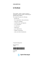
In This Guide...
In This Guide...
This manual covers the Agilent 1290 Infinity II Flexible Pump (G7104A).
1 Introduction
This chapter gives an introduction to the module, instrument overview and
internal connectors.
2 Site Requirements and Specifications
This chapter provides information on environmental requirements, physical
and performance specifications.
3 Using the Pump
This chapter explains the operational parameters of the Agilent 1290
Infinity II Flexible Pump.
4 How to Optimize the Performance of Your Module
This chapter gives hints on how to optimize the performance or use
additional devices.
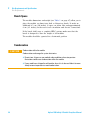
5 Troubleshooting and Diagnostics
Overview about the troubleshooting and diagnostic features.
6 Error Information
This chapter describes the meaning of error messages, and provides
information on probable causes and suggested actions how to recover from
error conditions.
7 Maintenance
This chapter describes the maintenance of the Agilent 1290 Infinity II
Flexible Pump.
Agilent 1290 Infinity II Flexible Pump User Manual
3
In This Guide...
8 Parts and Materials
This chapter provides information on parts for maintenance and repair.
9 Identifying Cables
This chapter provides information on cables used with the modules.
10 Hardware Information
This chapter describes the pump in more detail on hardware and
electronics.
11 LAN Configuration
This chapter provides information on connecting the module to the
controller software.
12 Appendix
This chapter provides additional information on safety, legal and web.
4
Agilent 1290 Infinity II Flexible Pump User Manual
Contents
Contents
1 Introduction
9
Product Description 10
Features 11
Operating Principle 12
Positions of the Multi Purpose Valve
Leak and Waste Handling 19
14
2 Site Requirements and Specifications
23
Site Requirements 24
Physical Specifications 27
Performance Specifications 28
3 Using the Pump
31
Magnets 32
Turn on/off 33
Status Indicators 34
Best Practices 35
4 How to Optimize the Performance of Your Module
Delay Volume and Extra-Column Volume 40
How to Configure the Optimum Delay Volume
How to Achieve Higher Resolution 43
Using Solvent Calibration Tables 46
5 Troubleshooting and Diagnostics
User Interfaces 48
Agilent Lab Advisor Software
6 Error Information
39
41
47
49
51
What Are Error Messages 53
General Error Messages 54
Pump Error Messages 60
Agilent 1290 Infinity II Flexible Pump User Manual
5
Contents
7 Maintenance
79
Introduction to Maintenance 81
Warnings and Cautions 82
Overview of Maintenance 84
Cleaning the Module 85
Install Fittings and Capillaries 86
Remove and Install Doors 87
Replace the Pressure Sensor 88
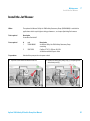
Replace the Inlet Weaver 90
Replace the Inlet Valve 92
Replace the Outlet Valve 93
Remove the Jet Weaver 95
Install the Jet Weaver 97
Replace the Seal Wash Pump 99
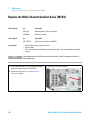
Replace the Multi-Channel Gradient Valve (MCGV) 100
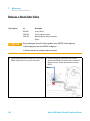
Release a Stuck Inlet Valve 102
Pump Head Procedures 104
Replace the Multi Purpose Valve 133
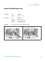
Replace Parts of the Multi Purpose Valve 135
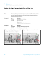
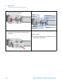
Replace the High Pressure Outlet Filter or Filter Frit 136
Replace Parts of the Inline Filter 138
Replace the Module Firmware 140
Prepare the Pump Module for Transport 141
8 Parts and Materials
143
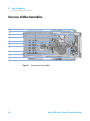
Overview of Main Assemblies 144
Flow Connections 146
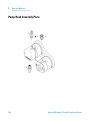
Pump Head Assembly Parts 148
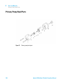
Primary Pump Head Parts 150
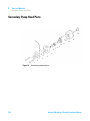
Secondary Pump Head Parts 152
Multi Purpose Valve 154
Cover Parts 155
Accessory Kit 156
Tool Kit 157
Tools 158
6
Agilent 1290 Infinity II Flexible Pump User Manual
Contents
9 Identifying Cables
161
Cable Overview 162
Analog Cables 164
Remote Cables 166
CAN/LAN Cables 170
Agilent Module to PC 171
USB Cables 172
10 Hardware Information
173
Firmware Description 174
Electrical Connections 177
Interfaces 179
Setting the 8-bit Configuration Switch
Early Maintenance Feedback 187
Instrument Layout 188
11 LAN Configuration
184
189
What You Have To Do First 190
TCP/IP Parameter Configuration 191
Configuration Switch 192
Initialization Mode Selection 193
Dynamic Host Configuration Protocol (DHCP) 197
Link Configuration Selection 200
Automatic configuration with Bootp 201
Manual Configuration 211
PC and User Interface Software Setup Setup 216
12 Appendix
219
General Safety Information 220
Waste Electrical and Electronic Equipment Directive
Radio Interference 227
Sound Emission 228
Agilent Technologies on Internet 229
Agilent 1290 Infinity II Flexible Pump User Manual
226
7
Contents
8
Agilent 1290 Infinity II Flexible Pump User Manual
Agilent 1290 Infinity II Flexible Pump User Manual
1
Introduction
Product Description
Features
10
11
Operating Principle
12
Positions of the Multi Purpose Valve
Leak and Waste Handling
Waste Concept 21
14
19
This chapter gives an introduction to the module, instrument overview and
internal connectors.
Agilent Technologies
9
1
Introduction
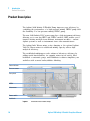
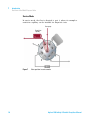
Product Description
Product Description
The Agilent 1290 Infinity II Flexible Pump improves your efficiency by
combining the performance of a high- pressure mixing UHPLC pump with
the flexibility of a low- pressure mixing UHPLC pump.
The new 1290 Infinity II LC power range has a high instrument efficiency,
allowing you to run any HPLC and UHPLC method. ISET enables you to
transfer existing methods from different instrument modules - current
Agilent systems as well as instruments from other manufacturers.
The Agilent Inlet Weaver mixer, active damping or the optional Agilent
V380 Jet Weaver mixer for additional mixing capacity achieve high
analytical efficiency.
The established multipurpose valve enhances laboratory efficiency by
adding useful functionalities, for example, mixer in/out switch, filter
backflush or automatic purge, and BlendAssist software simplifies your
workflow with accurate buffer/additive blending.
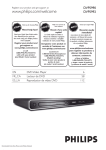
HiVijh^cY^XVidg
EgZhhjgZhZchdg
Ejbe]ZVY
B8<K
>caZilZVkZg
EdlZghl^iX]
AZV`YgV^c
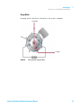
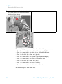
Figure 1
10
Overview of the Flexible Pump
Agilent 1290 Infinity II Flexible Pump User Manual
1
Introduction
Features
Features
• High performance in terms of accuracy and precision for flow and
composition.
• High power range combining high pressure up to 1300 bar and high
analytical flow rates up to 5 mL/min for high chromatographic
performance.
• Integrated high efficiency degasser with low internal volume is based on
PTFE AF technology and has a fast change- over of solvents for purging
and priming the pump.
• High solvent mixing efficiency before reaching the pump head due to
the established Inlet Weaver technology.
• Active damping with independently controllable high resolution pump
drives and firmware- embedded tuning algorithms significantly reduce
ripples and associated UV noise, switchable V380 Jet Weaver for extra
mixing volume.
• A multipurpose valve enables automatic software- embedded
functionalities such as switching the optional mixer in and out, flushing
back the inline filter or automatic purging.
• The unique Intelligent System Emulation Technology (ISET) enables the
emulation of existing Agilent 1100, 1200 and 1260 Infinity Series
instruments, as well as Waters Alliance, Waters H- Class and Shimadzu
Prominence instruments.
• Precise and accurate buffer/additive blending using the new software
feature BlendAssist, implemented in the pump driver.
• Built- in active seal- wash for increased uptime.
Agilent 1290 Infinity II Flexible Pump User Manual
11
1
Introduction
Operating Principle
Operating Principle
The pump head comprises two pump chambers in series with independent
high- resolution motion control. A pressure sensor in the flow path
monitors the pressure. The pump control uses this signal for minimizing
the pressure ripple in order to achieve highest flow precision. A stable
flow can be delivered even in case of eventual small internal leaks, which
can be compensated automatically. A heat exchanger between two pump
chambers strongly reduces thermal effects due to solvent compression
under very high pressures.
As solvents are compressed by the pump head and expand further down
the flow path, for example in the column, the volumetric flow is changed
depending on the compressibility of the liquid. Agilent control software
allows specifying pure solvents, pre- mixed solvents and solvent gradients.
Associated Agilent solvent libraries are used by the pump control for
enhanced flow accuracy, which is required for cross- instrument or
cross- system reproducibility and method compatibility.
A high resolution encoder unit is attached to the pump drives, which
divides a single turn into 65000 steps. Each step corresponds to a volume
of about 300 pL, which allows an extremely precise control.
12
Agilent 1290 Infinity II Flexible Pump User Manual
Introduction
Operating Principle
1
Bjai^hVbeaZg
EgZhhjgZhZchdg
Bjai^ejgedhZ
kVakZ
9Z\VhhZg
HZValVh]ejbe
?Zi
LZVkZg
Ejbe]ZVY
B8<K
>caZilZVkZg
Figure 2
HZValVh]hZchdg
The hydraulic path
Agilent 1290 Infinity II Flexible Pump User Manual
13
1
Introduction
Positions of the Multi Purpose Valve
Positions of the Multi Purpose Valve
The Multi Purpose Valve allows easy software controlled switching between
different modes of operation.
Normal Operating Mode Without Mixer
In normal operating mode, the flow comes from the pump head, passes
the pressure sensor and arrives at the central port of the Multi Purpose
Valve. The flow passes the inline filter and leaves the valve through port 4
to the system (autosampler etc.).
From pump
To system
Inline filter
Figure 3
14
Valve position in normal operating mode without mixer
Agilent 1290 Infinity II Flexible Pump User Manual
Introduction
Positions of the Multi Purpose Valve
1
Purge Mode
In purge mode, the flow is diverted to the waste container.
From pump
To waste
Figure 4
Valve position in purge mode
Agilent 1290 Infinity II Flexible Pump User Manual
15
1
Introduction
Positions of the Multi Purpose Valve
Normal Operating Mode With Mixer
In this mode, the flow passes an optional Jet Weaver and the inline filter.
This configuration is recommended for special applications which require
an increased mixing efficiency.
From pump
Jet Weaver
To system
Inline filter
Figure 5
16
Valve position in normal operating mode with mixer
Agilent 1290 Infinity II Flexible Pump User Manual
Introduction
Positions of the Multi Purpose Valve
1
Filter Flush Mode
This mode is used for cleaning the inline filter by back- flushing it. The
flow goes to port 5, passes the inline filter in opposite direction and
leaves to the waste through port 7.
From pump
To waste
Inline filter
Figure 6
Valve position in filter flush mode
Agilent 1290 Infinity II Flexible Pump User Manual
17
1
Introduction
Positions of the Multi Purpose Valve
Service Mode
In service mode, the flow is diverted to port 3, where for example a
restriction capillary can be installed for diagnostic tests.
From pump
Restriction
capillary
Figure 7
18
Valve position in service mode
Agilent 1290 Infinity II Flexible Pump User Manual
Introduction
Leak and Waste Handling
1
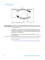
Leak and Waste Handling
The 1290 Infinity II Series has been designed for safe leak and waste
handling. It is important that all security concepts are understood and
instructions are carefully followed.
Figure 8
Leak and waste handling concept (overview - typical stack configuration as an
example)
Agilent 1290 Infinity II Flexible Pump User Manual
19
1
Introduction
Leak and Waste Handling
The solvent cabinet is designed to store a maximum volume of 6 L solvent.
The maximum volume for an individual bottle stored in the solvent cabinet
should not exceed 4 L. For details, see the usage guideline for the Agilent
1200 Infinity Series Solvent Cabinets (a printed copy of the guideline has
been shipped with the solvent cabinet, electronic copies are available on
the Internet).
All leak plane outlets are situated in a consistent position so that all
Infinity and Infinity II modules can be stacked on top of each other. Waste
tubes are guided through a channel on the right hand side of the
instrument, keeping the front access clear from tubes.
The leak plane provides leak management by catching all internal liquid
leaks, guiding them to the leak sensor for leak detection, and passing
them on to the next module below, if the leak sensor fails. The leak sensor
in the leak plane stops the running system as soon as the leak detection
level is reached.
Solvent and condensate is guided through the waste channel into the
waste container:
• from the detector's flow cell outlet
• from the Multisampler needle wash port
• from the Sample Cooler (condensate)
• from the Seal Wash Sensor
• from the pump's Purge Valve or Multipurpose Valve
The waste tube connected to the leak pan outlet on each of the bottom
instruments guides the solvent to a suitable waste container.
20
Agilent 1290 Infinity II Flexible Pump User Manual
Introduction
Leak and Waste Handling
1
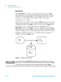
Waste Concept
Agilent recommends using the 6 L waste can with 1 Stay Safe cap GL45
with 4 ports (5043- 1221) for optimal and safe waste disposal. If you
decide to use your own waste solution, make sure that the tubes don't
immerse in the liquid.
Agilent 1290 Infinity II Flexible Pump User Manual
21
1
22
Introduction
Leak and Waste Handling
Agilent 1290 Infinity II Flexible Pump User Manual
Agilent 1290 Infinity II Flexible Pump User Manual
2
Site Requirements and Specifications
Site Requirements
24
Physical Specifications
27
Performance Specifications
28
This chapter provides information on environmental requirements, physical and
performance specifications.
Agilent Technologies
23
2
Site Requirements and Specifications
Site Requirements
Site Requirements
A suitable environment is important to ensure optimal performance of the
instrument.
Power Considerations
The module power supply has wide ranging capability. It accepts any line
voltage in the range described in Table 1 on page 27. Consequently there
is no voltage selector in the rear of the module. There are also no
externally accessible fuses, because automatic electronic fuses are
implemented in the power supply.
WA R N I N G
Hazard of electrical shock or damage of your instrumentation
can result, if the devices are connected to a line voltage higher than specified.
➔ Connect your instrument to the specified line voltage only.
WA R N I N G
The module is partially energized when switched off, as long as the power cord is
plugged in.
Repair work at the module can lead to personal injuries, e.g. electrical shock, when
the cover is opened and the module is connected to power.
➔ Always unplug the power cable before opening the cover.
➔ Do not connect the power cable to the instrument while the covers are removed.
CAUTION
Inaccessible power plug.
In case of emergency it must be possible to disconnect the instrument from the power
line at any time.
➔ Make sure the power connector of the instrument can be easily reached and
unplugged.
➔ Provide sufficient space behind the power socket of the instrument to unplug the
cable.
24
Agilent 1290 Infinity II Flexible Pump User Manual
2
Site Requirements and Specifications
Site Requirements
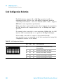
Power Cords
Different power cords are offered as options with the module. The female
end of all power cords is identical. It plugs into the power- input socket at
the rear. The male end of each power cord is different and designed to
match the wall socket of a particular country or region.
WA R N I N G
Absence of ground connection or use of unspecified power cord
The absence of ground connection or the use of unspecified power cord can lead to
electric shock or short circuit.
➔ Never operate your instrumentation from a power outlet that has no ground
connection.
➔ Never use a power cord other than the Agilent Technologies power cord designed
for your region.
WA R N I N G
Use of unsupplied cables
Using cables not supplied by Agilent Technologies can lead to damage of the
electronic components or personal injury.
➔ Never use cables other than the ones supplied by Agilent Technologies to ensure
proper functionality and compliance with safety or EMC regulations.
WA R N I N G
Unintended use of supplied power cords
Using power cords for unintended purposes can lead to personal injury or damage of
electronic equipment.
➔ Never use the power cords that Agilent Technologies supplies with this instrument
for any other equipment.
Agilent 1290 Infinity II Flexible Pump User Manual
25
2
Site Requirements and Specifications
Site Requirements
Bench Space
The module dimensions and weight (see Table 1 on page 27) allow you to
place the module on almost any desk or laboratory bench. It needs an
additional 2.5 cm (1.0 inches) of space on either side and approximately
8 cm (3.1 inches) in the rear for air circulation and electric connections.
If the bench shall carry a complete HPLC system, make sure that the
bench is designed to bear the weight of all modules.
The module should be operated in a horizontal position.
Condensation
CAUTION
Condensation within the module
Condensation can damage the system electronics.
➔ Do not store, ship or use your module under conditions where temperature
fluctuations could cause condensation within the module.
➔ If your module was shipped in cold weather, leave it in its box and allow it to warm
slowly to room temperature to avoid condensation.
26
Agilent 1290 Infinity II Flexible Pump User Manual
2
Site Requirements and Specifications
Physical Specifications
Physical Specifications
Table 1
Physical Specifications
Type
Specification
Weight
16.1 kg (35.5 lbs)
Dimensions
(height × width × depth)
180 x 396 x 436 mm
(7.1 x 15.6 x 17.2 inches)
Line voltage
100 – 240 V~, ± 10 %
Line frequency
50 or 60 Hz, ± 5 %
Power consumption
120 VA / 110 W
Ambient operating
temperature
4 – 55 °C (39 – 131 °F)
Ambient non-operating
temperature
-40 – 70 °C (-40 – 158 °F)
Humidity
< 95 % r.h. at 40 °C (104 °F)
Operating altitude
Up to 3000 m (9842 ft)
Non-operating altitude
Up to 4600 m (15092 ft)
For storing the module
Safety standards:
IEC, EN, CSA, UL
Installation category II, Pollution degree 2
For indoor use only.
Agilent 1290 Infinity II Flexible Pump User Manual
Comments
Wide-ranging
capability
Non-condensing
27
2
Site Requirements and Specifications
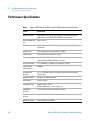
Performance Specifications
Performance Specifications
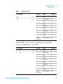
Table 2
28
Agilent 1290 Infinity II Flexible Pump (G7104A) Performance Specifications
Feature
Specification
Hydraulic system
Dual pistons in series pump with proprietary servo-controlled variable
stroke design and smooth motion control for active damping.
Pump resolution step
size
300 pL step size
Settable flow range
0.001 – 5 mL/min, in 0.001 mL/min increments (executed in 300 pL/step
increments).
Flow precision
≤0.07 % RSD or 0.01 min SD, whatever is greater
Flow accuracy
±1 % or ±10 µL/min, whatever is greater
Pressure range
up to 130 MPa (1300 bar) at 0 – 2 mL/min
ramping down to 80 MPa (800 bar) at 5 mL/min
Pressure pulsation
<1 % amplitude or <0.5 MPa (5 bar), whatever is greater
Compressibility
compensation
Automatic
Recommended
pH-range
1.0 – 12.5, solvents with pH <2.3 should not contain acid which attack
stainless steel.
Gradient formation
Low pressure quaternary mixing
Delay volume
As low as 350 µL
Composition range
Settable range: 0 – 100 %
Recommended range: 1 – 99 % or 5 µL/min
Composition
precision
<0.15 % RSD or 0.02 min SD, whatever is greater
Composition
accuracy
±0.4 % absolute (1 – 99 % B)
Number of solvent
4 out of maximum 26 solvents
Agilent 1290 Infinity II Flexible Pump User Manual
2
Site Requirements and Specifications
Performance Specifications
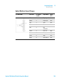
Table 2
Agilent 1290 Infinity II Flexible Pump (G7104A) Performance Specifications
Feature
Specification
Solvent selection
valve
Internal 4-solvent gradient formation valve included.
External 2x 12 solvent valve as option, fully integrated in the pump control
interface.
Degassing unit
Integrated.
Number of channels: 4, Internal volume per channel: 1.5 mL
Materials in contact
with solvent
TFE/PDD copolymer, FEP, PEEK, PPS, stainless steel, polyimide
Automatic Purge
Valve
Included, allows automatic inline-filter back-flush and automatic mixer
change, e.g. for optional TFA-mixer
Active Seal wash
Included
Intelligent System
Emulation
Technology (ISET)
Included
Communications
Controller-area network (CAN), RS232C, APG remote: ready, start, stop and
shutdown signals, LAN
Safety and
maintenance
Extensive diagnostics, error detection and display through included
Agilent LabAdvisor, leak detection, safe leak handling, leak output signal
for shutdown of the pumping system. Low voltage in major maintenance
areas.
GLP features
Early maintenance feedback (EMF) for continuous tracking of instrument
usage in terms of seal wear and volume of pumped mobile phase with
pre-defined and user settable limits and feedback messages. Electronic
records of maintenance and errors.
Housing
All materials are recyclable.
Agilent 1290 Infinity II Flexible Pump User Manual
29
2
30
Site Requirements and Specifications
Performance Specifications
Agilent 1290 Infinity II Flexible Pump User Manual
Agilent 1290 Infinity II Flexible Pump User Manual
3
Using the Pump
Magnets
Turn on/off
32
33
Status Indicators
34
Best Practices 35
Daily / Weekly tasks 35
Power up / Shut-down the pump 35
Prepare the pump 36
How to deal with solvents 37
Select channels for Multi-Channel Gradient Valve (MCGV)
37
This chapter explains the operational parameters of the Agilent 1290 Infinity II
Flexible Pump.
Agilent Technologies
31
3
Using the Pump
Magnets
Magnets
32
Agilent 1290 Infinity II Flexible Pump User Manual
Using the Pump
Turn on/off
3
Turn on/off
1
2
Power switch
(1) On
(2) Off
3
Agilent 1290 Infinity II Flexible Pump User Manual
33
3
Using the Pump
Status Indicators
Status Indicators
The module status indicator indicates one of six possible module
conditions:
Status indicators
1. Idle
2. Run mode
3. Not- ready. Waiting for a specific pre- run condition to be reached or
completed.
4. Error mode - interrupts the analysis and requires attention
(for example a leak or defective internal components).
5. Resident mode (blinking) - for example during update of main
firmware.
6. Bootloader mode (fast blinking). Try to re- boot the module or try a
cold- start. Then try a firmware update.
34
Agilent 1290 Infinity II Flexible Pump User Manual
3
Using the Pump
Best Practices
Best Practices
Daily / Weekly tasks
Daily tasks
• Replace mobile phase based on water/buffer.
• Replace organic mobile phase latest every 2nd day.
• Check seal wash solvent.
• Run conditioning with composition of your application.
Weekly tasks
• Change seal wash solvent (10 % / 90 % isopropanol/water) and bottle.
• Flush all channels with water to remove salt deposits.
• Visually inspect solvent filters. Clean or exchange if necessary.
Power up / Shut-down the pump
Power up the pump
• Use new or different mobile phase (as required).
• Purge pump heads with 2.5 – 3 mL/min for 5 min.
• Condition pump heads for 10 – 20 min.
Long-term shut-down of the pump
• Flush system with water to remove buffer.
• Use recommended solvents to store the system.
• Power off the pump or system.
Agilent 1290 Infinity II Flexible Pump User Manual
35
3
Using the Pump
Best Practices
Prepare the pump
Purge
Use the Purge function to:
• fill the pump,
• exchange a solvent,
• remove air bubbles in tubes and pump heads.
Condition
Use the Conditioning function:
• daily when starting the pump,
• to minimize pressure ripple by dissolving air bubbles in pump heads.
NOTE
Condition your complete system with solvents and composition of your application (for
example 50 %/50 % A/B at 0.5 mL/min.
Seal wash
The seal wash function runs continuously and is controlled by the seal
wash sensor. This guarantees a maximum seal life time.
CAUTION
Contaminated seal wash solvent
➔ Do not recycle seal wash solvent to avoid contamination.
➔ Weekly exchange seal wash solvent.
36
Agilent 1290 Infinity II Flexible Pump User Manual
3
Using the Pump
Best Practices
How to deal with solvents
• Use clean bottles only.
• Exchange water- based solvents daily.
• Select solvent volume to be used up within 1 – 2 days.
• Use only HPLC- grade solvents and water filtered through 0.2 µm filters.
• Label bottles correctly with bottle content, and filling date / expiry
date.
• Use solvent inlet filters.
• Reduce risk of algae growth: use brown bottles for aqueous solvents,
avoid direct sunlight.
Select channels for Multi-Channel Gradient Valve (MCGV)
• Use lower channels (A and/or D) for buffer solutions.
• Regularly flush all MCGV channels with water to remove possible salt
deposits.
• Check compatibility of buffers and organic solvents to avoid
precipitation.
Agilent 1290 Infinity II Flexible Pump User Manual
37
3
38
Using the Pump
Best Practices
Agilent 1290 Infinity II Flexible Pump User Manual
Agilent 1290 Infinity II Flexible Pump User Manual
4
How to Optimize the Performance of
Your Module
Delay Volume and Extra-Column Volume
Delay Volume 40
40
How to Configure the Optimum Delay Volume
How to Achieve Higher Resolution
Using Solvent Calibration Tables
41
43
46
This chapter gives hints on how to optimize the performance or use additional
devices.
Agilent Technologies
39
4
How to Optimize the Performance of Your Module
Delay Volume and Extra-Column Volume
Delay Volume and Extra-Column Volume
The delay volume is defined as the system volume between the point of
mixing in the pump and the top of the column.
The extra- column volume is defined as the volume between the injection
point and the detection point, excluding the volume in the column.
Delay Volume
In gradient separations, this volume causes a delay between the mixture
changing in the pump and that change reaching the column. The delay
depends on the flow rate and the delay volume of the system. In effect,
this means that in every HPLC system there is an additional isocratic
segment in the gradient profile at the start of every run. Usually the
gradient profile is reported in terms of the mixture settings at the pump
and the delay volume is not quoted even though this will have an effect
on the chromatography. This effect becomes more significant at low flow
rates and small column volumes and can have a large impact on the
transferability of gradient methods. It is important, therefore, for fast
gradient separations to have small delay volumes, especially with narrow
bore columns (e.g., 2.1 mm i.d.) as often used with mass spectrometric
detection.
The delay volume in a system includes the volume in the pump from the
point of mixing, connections between pump and autosampler, volume of
the flow path through the autosampler and connections between
autosampler and column.
For the 1290 Infinity II Flexible Pump, all pump parts downstream the
MCGV contribute to the delay volume, i.e. inlet weaver, pump heads,
capillary connections, filters and the optional Jet Weaver.
40
Agilent 1290 Infinity II Flexible Pump User Manual
How to Optimize the Performance of Your Module
How to Configure the Optimum Delay Volume
4
How to Configure the Optimum Delay Volume
The design of the 1290 Infinity Quaternary Pump offers a strongly
decreased delay volume compared to standard 600 bar pressure pumps.
For the 1290 Infinity Quaternary Pump, mixing is done in the
multi- channel gradient valve at ambient pressure. As all pump parts in
the flow path after mixing contribute to the delay volume, this includes
also pump heads of the quaternary pump, flow connections, filters, mixers
etc. Therefore the delay volume of a quaternary pump is by design larger
than that of a binary pump.
All listed components including the inlet weaver and pump heads ensure a
good mixing performance resulting in excellent composition precision and
accuracy, highly reproducible retention times and low baseline noise. This
ensures best results for most applications.
Per default, the 1290 Infinity Quaternary Pump does not require and
include a Jet Weaver, as solvents are mixed in the MCGV and mixing is
further improved in the inlet weaver, pump heads and subsequent parts in
the flow path. Therefore, no Jet Weaver is required for most applications.
The V380 Jet Weaver high performance mixer is optionally available for
demanding applications, which use solvents in different channels (for
example A versus B), that differ strongly in their UV/Vis absorption, for
example by using trifluoroacetic acid (TFA) as a modifier, which has a
high absorbance. Solvent packages created by the pump may persist until
the solvent reaches the detector flow cell. Absorption fluctuations can
then show up as baseline noise, also referred to as mixing noise.
Applications like impurity quantitation or lowest level compound detection
require minimizing this noise. The V380 Jet Weaver strongly improves
mixing and therefore reduces baseline noise and improves sensitivity in
detection. Patented Agilent microfluidic technology offers high mixing
performance at a low internal volume of 380 µL, which is the physical
volume of all channels. It contributes with 150 µL to the pump delay
volume (< 350 µL without Jet Weaver), which is the partial mixer volume
that creates a composition change corresponding to the delay volume.
Agilent 1290 Infinity II Flexible Pump User Manual
41
4
How to Optimize the Performance of Your Module
How to Configure the Optimum Delay Volume
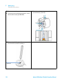
Figure 9
The Jet Weaver mixer
The installation procedure is illustrated in “Install the Jet Weaver” on
page 97.
42
Agilent 1290 Infinity II Flexible Pump User Manual
4
How to Optimize the Performance of Your Module
How to Achieve Higher Resolution
How to Achieve Higher Resolution
Increased resolution in a separation will improve the qualitative and
quantitative data analysis, allow more peaks to be separated or offer
further scope for speeding up the separation. This section explains how
resolution can be increased by examining the following points:
• Optimize selectivity
• Smaller particle- size packing
• Longer Columns
• Shallower gradients, faster flow
Resolution between two peaks is described by the resolution equation:
where
• Rs=resolution,
• N=plate count (measure of column efficiency),
• α=selectivity (between two peaks),
• k2=retention factor of second peak (formerly called capacity factor).
The term that has the most significant effect on resolution is the
selectivity, α, and practically varying this term involves changing the type
of stationary phase (C18, C8, phenyl, nitrile etc.), the mobile phase and
temperature to maximize the selectivity differences between the solutes to
be separated. This is a substantial piece of work which is best done with
an automated method development system which allows a wide range of
conditions on different columns and mobile phases to be assessed in an
ordered scouting protocol. This section considers how to get higher
resolution with any chosen stationary and mobile phases. If an automated
method development system was used in the decision on phases it is likely
that short columns were used for fast analysis in each step of the
scouting.
The resolution equation shows that the next most significant term is the
plate count or efficiency, N, and this can be optimized in a number of
Agilent 1290 Infinity II Flexible Pump User Manual
43
4
How to Optimize the Performance of Your Module
How to Achieve Higher Resolution
ways. N is inversely proportional to the particle size and directly
proportional to the length of a column and so smaller particle size and a
longer column will give a higher plate number. The pressure rises with the
inverse square of the particle size and proportionally with the length of
the column. This is the reason that the 1290 Infinity LC system was
designed to go to 1200 bar so that it can run sub- two- micron particles
and column length can be increased to 100 mm or 150 mm. There are
even examples of 100 mm and 150 mm columns linked to give 250 mm
length. Resolution increases with the square root of N so doubling the
length of the column will increase resolution by a factor of 1.4. What is
achievable depends on the viscosity of the mobile phase as this relates
directly to the pressure. Methanol mixtures will generate more back
pressure than acetonitrile mixtures. Acetonitrile is often preferred because
peak shapes are better and narrower in addition to the lower viscosity but
methanol generally yields better selectivity (certainly for small molecules
less than about 500 Da). The viscosity can be reduced by increasing the
temperature but it should be remembered that this can change the
selectivity of the separation. Experiment will show if this leads to increase
or decrease in selectivity. As flow and pressure are increased it should be
remembered that frictional heating inside the column will increase and
that can lead to slightly increased dispersion and possibly a small
selectivity change both of which could be seen as a reduction in
resolution. The latter case might be offset by reducing the temperature of
the thermostat by a few degrees and again experiment will reveal the
answer.
The van Deemter curve shows that the optimum flow rate through an STM
column is higher than for larger particles and is fairly flat as the flow rate
increases. Typical, close to optimum, flow rates for STM columns are:
2 ml/min for 4.6 mm i.d.; and 0.4 ml/min for 2.1 mm i.d. columns.
In isocratic separations, increasing the retention factor, k, results in better
resolution because the solute is retained longer. In gradient separations
the retention is described by k* in the following equation:
where:
• k* = mean k value,
• tG = time length of gradient (or segment of gradient) (min),
44
Agilent 1290 Infinity II Flexible Pump User Manual
How to Optimize the Performance of Your Module
How to Achieve Higher Resolution
4
• F = flow (ml/min),
• Vm = column delay volume,
• Δ%B = change in fraction of solvent B during the gradient,
• S = constant (ca. 4- 5 for small molecules).
This shows that k and hence resolution can be increased by having a
shallower gradient (2 to 5 %/min change is a guideline), higher flow rate
and a smaller volume column. This equation also shows how to speed up
an existing gradient – if the flow is doubled but the gradient time is
halved, k* remains constant and the separation looks the same but
happens in half the time. Recently published research has shown how a
shorter STM column (at temperatures above 40 °C) can generate higher
peak capacity than a longer STM column by virtue of running it faster.
(Refer to Petersson et al., J.Sep.Sci, 31, 2346- 2357, 2008, Maximizing
peak capacity and separation speed in liquid chromatography).
Agilent 1290 Infinity II Flexible Pump User Manual
45
4
How to Optimize the Performance of Your Module
Using Solvent Calibration Tables
Using Solvent Calibration Tables
Importing Solvent Calibration Tables
RC.NET based Agilent graphical user interfaces (ChemStation, EZChrom
Elite, OpenLab etc.) include data for most commonly used solvents in
HPLC. This data contains solvent properties and is used for optimum
pump control in order to ensure best flow and composition accuracy.
If your solvent is not included to the software, please check the Agilent
web site
http://www.chem.agilent.com/en- US/Support/Downloads/firmware/Pages/LC.aspx
for additional libraries (registration required), which also provides updates
and optimized data.
If your solvent is neither available in the user interface nor in the library,
please use generic solvents. "Generic aequeous" gives good results for most
solvent mixtures with at least 50 % water, which have similar properties
as pure water. For other solvents with high organic percentage, "Generic
organic" gives a good approximation.
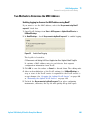
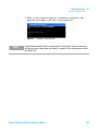
Importing Solvent Calibration in ChemStation
1 Go to menu Instrument > Instrument configuration.
2 In the Instrument Configuration screen choose your module and click
Configure.
3 Click Configure Solvent Type Catalogs.
4 In Solvent Type Catalogs click Import.
5 Navigate to the location of the solvent calibration table and click Open.
6 The new solvent will now appear in the Solvent Type Catalogs.
46
Agilent 1290 Infinity II Flexible Pump User Manual
Agilent 1290 Infinity II Flexible Pump User Manual
5
Troubleshooting and Diagnostics
User Interfaces
48
Agilent Lab Advisor Software
49
Overview about the troubleshooting and diagnostic features.
Agilent Technologies
47
5
Troubleshooting and Diagnostics
User Interfaces
User Interfaces
• Depending on the user interface, the available tests and the
screens/reports may vary.
• Preferred tool should be Agilent Lab Advisor Software, see “Agilent Lab
Advisor Software” on page 49.
• The Agilent OpenLab ChemStation C.01.03 and above do not include
any maintenance/test functions.
• Screenshots used within these procedures are based on the Agilent Lab
Advisor Software.
48
Agilent 1290 Infinity II Flexible Pump User Manual
Troubleshooting and Diagnostics
Agilent Lab Advisor Software
5
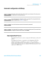
Agilent Lab Advisor Software
The Agilent Lab Advisor Software is a standalone product that can be
used with or without chromatographic data system. Agilent Lab Advisor
helps to manage the lab for high- quality chromatographic results by
providing a detailed system overview of all connected analytical
instruments with instrument status, Early Maintenance Feedback counters
(EMF), instrument configuration information, and diagnostic tests. By the
push of a button, a detailed diagnostic report can be generated. Upon
request, the user can send this report to Agilent for a significantly
improved troubleshooting and repair process.
The Agilent Lab Advisor software is available in two versions:
• Lab Advisor Basic
• Lab Advisor Advanced
Lab Advisor Basic is included with every Agilent 1200 Infinity Series and
Infinity II Series pump.
The Lab Advisor Advanced features can be unlocked by purchasing a
license key, and include real- time monitoring of instrument actuals, all
various instrument signals, and state machines. In addition, all diagnostic
test results, calibration results, and acquired signal data can be uploaded
to a shared network folder. The Review Client included in Lab Advisor
Advanced allows to load and examine the uploaded data no matter on
which instrument it was generated. This makes Data Sharing an ideal tool
for internal support groups and users who want to track the instrument
history of their analytical systems.
The optional Agilent Maintenance Wizard Add- on provides an easy- to- use,
step- by- step multimedia guide for performing preventive maintenance on
Agilent 1200 Infinity and Infinity II Series instruments.
The tests and diagnostic features that are provided by the Agilent Lab
Advisor software may differ from the descriptions in this manual. For
details, refer to the Agilent Lab Advisor software help files.
Agilent 1290 Infinity II Flexible Pump User Manual
49
5
50
Troubleshooting and Diagnostics
Agilent Lab Advisor Software
Agilent 1290 Infinity II Flexible Pump User Manual
Agilent 1290 Infinity II Flexible Pump User Manual
6
Error Information
What Are Error Messages
53
General Error Messages 54
Timeout 54
Shutdown 54
Remote Timeout 55
Lost CAN Partner 56
Leak Sensor Short 56
Leak Sensor Open 57
Compensation Sensor Open
Compensation Sensor Short
Fan Failed 59
Leak 59
57
58
Pump Error Messages 60
Pressure of quaternary pump above upper limit 60
Pressure below lower limit 60
Target pressure not reached for quaternary pump degasser
Solvent counter exceeded limit 61
Waste counter limit exceeded 62
Flow rate limit exceeded 62
Quaternary pump shutdown during analysis 63
Reading the pump encoder tag failed 63
Writing the pump encoder tag failed 64
Pump drive blocked or encoder failed 64
Drive current too low 65
Drive current too high 65
Drive timeout 66
Overcurrent of pump drive 66
Deliver underrun 67
Agilent Technologies
61
51
6
Error Information
Agilent Lab Advisor Software
Defect connection between main board and pump drive encoder
Pump drive encoder defect 68
Multi Purpose Valve failed 68
Reading of multi purpose valve tag failed 69
Pump drive encoder rollover 69
Drive position limit 70
Insufficient power of drive encoder LED 70
Drive encoder error 70
Writing the multi purpose valve tag failed 71
Unknown multi purpose valve type 71
Pump drive encoder error 71
Pump drive error 72
Maximum stroke is too short 72
Pump drive stop not found 73
Timeout: Wait for Composition 73
Timeout: Wait for run volume 74
Timeout: Wait for Volume 74
Timeout: Wait for Flow 75
Timeout: Wait for Pressure 75
Drive Encoder failed 76
Drive phases differ too much in electric resistance 76
Degasser's pressure limit violation 77
Seal wash pump was missing when tried to turn on 77
Valve hardware overcurrent (MCGV) 78
67
This chapter describes the meaning of error messages, and provides
information on probable causes and suggested actions how to recover from
error conditions.
52
Agilent 1290 Infinity II Flexible Pump User Manual
Error Information
What Are Error Messages
6
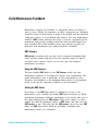
What Are Error Messages
Error messages are displayed in the user interface when an electronic,
mechanical, or hydraulic (flow path) failure occurs which requires
attention before the analysis can be continued (for example, repair, or
exchange of consumables is necessary). In the event of such a failure, the
red status indicator at the front of the module is switched on, and an
entry is written into the module logbook.
If an error occurs outside a method run, other modules will not be
informed about this error. If it occurs within a method run, all connected
modules will get a notification, all LEDs get red and the run will be
stopped. Depending on the module type, this stop is implemented
differently. For example, for a pump the flow will be stopped for safety
reasons. For a detector, the lamp will stay on in order to avoid
equilibration time. Depending on the error type, the next run can only be
started, if the error has been resolved, for example liquid from a leak has
been dried. Errors for presumably single time events can be recovered by
switching on the system in the user interface.
Special handling is done in case of a leak. As a leak is a potential safety
issue and may have occurred at a different module from where it has been
observed, a leak always causes a shutdown of all modules, even outside a
method run.
In all cases, error propagation is done via the CAN bus or via an APG
remote cable (see documentation for the APG interface).
Agilent 1290 Infinity II Flexible Pump User Manual
53
6
Error Information
General Error Messages
General Error Messages
General error messages are generic to all Agilent series HPLC modules
and may show up on other modules as well.
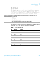
Timeout
Error ID: 0062
The timeout threshold was exceeded.
Probable cause
Suggested actions
1 The analysis was completed successfully,
Check the logbook for the occurrence and
source of a not-ready condition. Restart the
analysis where required.
and the timeout function switched off the
module as requested.
2 A not-ready condition was present during a
sequence or multiple-injection run for a
period longer than the timeout threshold.
Check the logbook for the occurrence and
source of a not-ready condition. Restart the
analysis where required.
Shutdown
Error ID: 0063
An external instrument has generated a shutdown signal on the remote
line.
The module continually monitors the remote input connectors for status
signals. A LOW signal input on pin 4 of the remote connector generates
the error message.
54
Agilent 1290 Infinity II Flexible Pump User Manual
Error Information
General Error Messages
Probable cause
Suggested actions
1 Leak detected in another module with a
Fix the leak in the external instrument before
restarting the module.
CAN connection to the system.
2 Leak detected in an external instrument
with a remote connection to the system.
3 Shut-down in an external instrument with a
remote connection to the system.
6
Fix the leak in the external instrument before
restarting the module.
Check external instruments for a shut-down
condition.
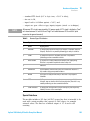
Remote Timeout
Error ID: 0070
A not- ready condition is still present on the remote input. When an
analysis is started, the system expects all not- ready conditions (for
example, a not- ready condition during detector balance) to switch to run
conditions within one minute of starting the analysis. If a not- ready
condition is still present on the remote line after one minute the error
message is generated.
Probable cause
Suggested actions
1 Not-ready condition in one of the
Ensure the instrument showing the not-ready
condition is installed correctly, and is set up
correctly for analysis.
instruments connected to the remote line.
2 Defective remote cable.
Exchange the remote cable.
3 Defective components in the instrument
Check the instrument for defects (refer to the
instrument’s documentation).
showing the not-ready condition.
Agilent 1290 Infinity II Flexible Pump User Manual
55
6
Error Information
General Error Messages
Lost CAN Partner
Error ID: 0071
During an analysis, the internal synchronization or communication
between one or more of the modules in the system has failed.
The system processors continually monitor the system configuration. If one
or more of the modules is no longer recognized as being connected to the
system, the error message is generated.
Probable cause
Suggested actions
1 CAN cable disconnected.
•
Ensure all the CAN cables are connected
correctly.
•
Ensure all CAN cables are installed
correctly.
2 Defective CAN cable.
Exchange the CAN cable.
3 Defective main board in another module.
Switch off the system. Restart the system, and
determine which module or modules are not
recognized by the system.
Leak Sensor Short
Error ID: 0082
The leak sensor in the module has failed (short circuit).
The current through the leak sensor is dependent on temperature. A leak
is detected when solvent cools the leak sensor, causing the leak sensor
current to change within defined limits. If the current increases above the
upper limit, the error message is generated.
Probable cause
Suggested actions
1 Defective leak sensor.
Please contact your Agilent service
representative.
2 Leak sensor incorrectly routed, being
Please contact your Agilent service
representative.
pinched by a metal component.
56
Agilent 1290 Infinity II Flexible Pump User Manual
Error Information
General Error Messages
6
Leak Sensor Open
Error ID: 0083
The leak sensor in the module has failed (open circuit).
The current through the leak sensor is dependent on temperature. A leak
is detected when solvent cools the leak sensor, causing the leak- sensor
current to change within defined limits. If the current falls outside the
lower limit, the error message is generated.
Probable cause
Suggested actions
1 Leak sensor not connected to the Power
Please contact your Agilent service
representative.
Switch board.
2 Defective leak sensor.
Please contact your Agilent service
representative.
3 Leak sensor incorrectly routed, being
Please contact your Agilent service
representative.
pinched by a metal component.
Compensation Sensor Open
Error ID: 0081
The ambient- compensation sensor (NTC) on the power switch board in the
module has failed (open circuit).
The resistance across the temperature compensation sensor (NTC) on the
power switch board is dependent on ambient temperature. The change in
resistance is used by the leak circuit to compensate for ambient
temperature changes. If the resistance across the sensor increases above
the upper limit, the error message is generated.
Probable cause
Suggested actions
1 Loose connection between the power
Please contact your Agilent service
representative.
switch board and the main board
2 Defective power switch board
Agilent 1290 Infinity II Flexible Pump User Manual
Please contact your Agilent service
representative.
57
6
Error Information
General Error Messages
Compensation Sensor Short
Error ID: 0080
The ambient- compensation sensor (NTC) on the power switch board in the
module has failed (open circuit).
The resistance across the temperature compensation sensor (NTC) on the
power switch board is dependent on ambient temperature. The change in
resistance is used by the leak circuit to compensate for ambient
temperature changes. If the resistance across the sensor falls below the
lower limit, the error message is generated.
Probable cause
Suggested actions
1 Defective power switch board
Please contact your Agilent service
representative.
2 Loose connection between the power
Please contact your Agilent service
representative.
switch board and the main board
58
Agilent 1290 Infinity II Flexible Pump User Manual
6
Error Information
General Error Messages
Fan Failed
Error ID: 0068
The cooling fan in the module has failed.
The hall sensor on the fan shaft is used by the main board to monitor the
fan speed. If the fan speed falls below a certain limit for a certain length
of time, the error message is generated.
Depending on the module, assemblies (e.g. the lamp in the detector) are
turned off to assure that the module does not overheat inside.
Probable cause
Suggested actions
1 Fan cable disconnected.
Please contact your Agilent service
representative.
2 Defective fan.
Please contact your Agilent service
representative.
3 Defective main board.
Please contact your Agilent service
representative.
Leak
Error ID: 0064
A leak was detected in the module.
The signals from the two temperature sensors (leak sensor and
board- mounted temperature- compensation sensor) are used by the leak
algorithm to determine whether a leak is present. When a leak occurs, the
leak sensor is cooled by the solvent. This changes the resistance of the
leak sensor which is sensed by the leak- sensor circuit on the main board.
Probable cause
Suggested actions
1 Loose fittings.
Ensure all fittings are tight.
2 Broken capillary.
Exchange defective capillaries.
Agilent 1290 Infinity II Flexible Pump User Manual
59
6
Error Information
Pump Error Messages
Pump Error Messages
These errors are pump specific.
Pressure of quaternary pump above upper limit
Error ID: 29163
The pressure has exceeded the upper pressure limit.
• Parameter: Measured pressure
Probable cause
Suggested actions
1 Blockage in flow path after the pressure
•
Check for blockages in the LC system, e.g. purge
valve, Jet Weaver, degraded column, column frits,
needle, needle seat, capillaries etc.
•
Check for particles in the solvent.
•
Decrease flow rate.
•
Increase pressure limit.
sensor.
2 Inappropriate settings (pressure limit, flow
rate).
Pressure below lower limit
Error ID: 29176
The pressure has dropped below the lower limit.
• Parameter: None
60
Probable cause
Suggested actions
1 Leak
Check for leaks.
2 Bottle empty
Check bottle filling.
3 Wrong solvent (viscosity)
Check solvent.
4 Inappropriate setting
Check flow rate and lower pressure limit.
5 Column degradation
Replace column.
Agilent 1290 Infinity II Flexible Pump User Manual
Error Information
Pump Error Messages
6
Target pressure not reached for quaternary pump degasser
Error ID: 29221
The target pressure of the quaternary pump degasser has not been
reached within the expected time.
• Parameter: Pressure in mbar
Probable cause
Suggested actions
1 Condensation in degasser chamber due to
Equilibrate and restart module.
temperature fluctuation.
2 Degasser is defect.
Please contact your Agilent service
representative.
Solvent counter exceeded limit
Error ID: 29146
The counter for the solvent volume has exceeded the limit, which has been
set in the user interface.
Probable cause
Suggested actions
1 No solvent present.
Refill solvent bottle.
2 Inappropriate setting.
Check solvent counter setting in user interface.
Agilent 1290 Infinity II Flexible Pump User Manual
61
6
Error Information
Pump Error Messages
Waste counter limit exceeded
Error ID: 29147
The counter for the waste volume has exceeded the limit, which has been
set in the user interface.
• Parameter: None
Probable cause
Suggested actions
1 The waste container is full.
Empty waste container.
2 Inappropriate setting for waste counter.
•
Reset waste counter.
•
Adjust waste counter limit.
Flow rate limit exceeded
Error ID: 29164
The flow rate of the quaternary pump has exceeded the limit, while the
pump runs in pressure controlled mode, e.g. during a pressure test.
• Parameter: None
Probable cause
Suggested actions
1 Leak
Check for leaks in the pump and flow path.
2 Bottle empty.
Fill solvent bottle.
3 Shutoff valve closed (if applicable).
Open shutoff valve.
4 Drift of pressure sensor (unlikely for short
Replace pressure sensor.
tests taking some minutes).
62
Agilent 1290 Infinity II Flexible Pump User Manual
Error Information
Pump Error Messages
6
Quaternary pump shutdown during analysis
Error ID: 29199
The quaternary pump has been shut down by the control software or
control module during an analysis.
• Parameter: 0 for off, 1 for standby.
Probable cause
Suggested actions
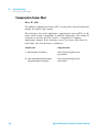
1 Pump has been shut down.
Restart pump.
Reading the pump encoder tag failed
Error ID: 29201
Reading the pump encoder tag has failed.
• Parameter: 1 – 2 referring to pump drive
Probable cause
Suggested actions
1 Defect connection between encoder and
Please contact your Agilent service
representative.
main board.
2 Missing or defect tag Defect connection
between tag and encoder.
Agilent 1290 Infinity II Flexible Pump User Manual
Please contact your Agilent service
representative.
63
6
Error Information
Pump Error Messages
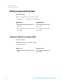
Writing the pump encoder tag failed
Error ID: 29200
Writing the pump encoder tag has failed.
• Parameter: 1 – 2 referring to pump drive
Probable cause
Suggested actions
1 Defect connection between encoder and
Please contact your Agilent service
representative.
main board.
2 Defect tag Defect connection between tag
and encoder.
Please contact your Agilent service
representative.
Pump drive blocked or encoder failed
Error ID: 29214
Pump drive blocked or encoder failed.
• Parameter: None
Probable cause
Suggested actions
1 Blockage of the pump drive Drive encoder
Please contact your Agilent service
representative.
failed.
64
Agilent 1290 Infinity II Flexible Pump User Manual
Error Information
Pump Error Messages
6
Drive current too low
Error ID: 29205
The current consumption of the pump drive is too low.
• Parameter: 1 – 2 referring to pump drive
Probable cause
Suggested actions
1 Drive motor defect.
Please contact your Agilent service
representative.
2 Wrong/missing connection of pump drive to
Please contact your Agilent service
representative.
main board.
Drive current too high
Error ID: 29236
The current consumption of the pump drive is too high.
• Parameter: 1 – 2 referring to pump drive
Probable cause
Suggested actions
1 Blockage of system before pressure sensor.
Check for blockage of e.g. outlet valve filter frit,
Multi Purpose Valve, heat exchanger.
2 Drive motor defect.
Please contact your Agilent service
representative.
Agilent 1290 Infinity II Flexible Pump User Manual
65
6
Error Information
Pump Error Messages
Drive timeout
Error ID: 29204
Movement of drive during initialization is blocked mechanically.
• Parameter: 1 – 2 referring to pump drive
Probable cause
Suggested actions
1 Blockage in flow path
Remove capillary connection to system, check
outlet filter, check valves, check pump head.
2 Blockage of pump drive Drive motor defect.
Please contact your Agilent service
representative.
Overcurrent of pump drive
Error ID: 29202
The current consumption of the pump drive is too high.
• Parameter: 1 – 2 referring to pump drive
66
Probable cause
Suggested actions
1 Blockage of system before pressure sensor.
Check for blockage of e.g. outlet valve filter frit,
Multi Purpose Valve, heat exchanger.
2 Drive motor defect.
Please contact your Agilent service
representative.
Agilent 1290 Infinity II Flexible Pump User Manual
Error Information
Pump Error Messages
6
Deliver underrun
Error ID: 29233
Internal error.
• Parameter: None
Probable cause
Suggested actions
1 Internal error.
Please contact your Agilent service
representative.
2 Firmware issue
Use a minimum firmware revision of B.06.55
Defect connection between main board and pump drive encoder
Error ID: 29208
Defect connection between main board and pump drive encoder.
• Parameter: 1 – 2 referring to pump drive
Probable cause
Suggested actions
1 Defect connection between main board and
Please contact your Agilent service
representative.
pump drive encoder.
2 Defect encoder.
Agilent 1290 Infinity II Flexible Pump User Manual
Please contact your Agilent service
representative.
67
6
Error Information
Pump Error Messages
Pump drive encoder defect
Error ID: 29209
Defect pump drive encoder.
• Parameter: 1 – 2 referring to pump drive
Probable cause
Suggested actions
1 Defect encoder.
Please contact your Agilent service
representative.
Multi Purpose Valve failed
Error ID: 29231
Lost steps of the purge valve encoder.
• Parameter: None
Probable cause
Suggested actions
1 Multi purpose valve drive mechanically
•
Check installation of multi purpose valve
head.
•
Replace multi purpose valve head.
blocked or defect.
68
Agilent 1290 Infinity II Flexible Pump User Manual
Error Information
Pump Error Messages
6
Reading of multi purpose valve tag failed
Error ID: 29240
Reading the multi purpose valve tag failed.
• Parameter: None
Probable cause
Suggested actions
1 Reading of multi purpose valve tag failed.
Check cable connection.
2 Multi purpose valve head tag defect or
Replace multi purpose valve head.
empty.
3 Multi purpose valve tag reader is defect.
Please contact your Agilent service
representative.
Pump drive encoder rollover
Error ID: 29232
Invalid pump drive encoder signals have been detected.
• Parameter: 1 – 2 referring to pump drive
Probable cause
Suggested actions
1 Pump drive encoder is defect.
Please contact your Agilent service
representative.
Agilent 1290 Infinity II Flexible Pump User Manual
69
6
Error Information
Pump Error Messages
Drive position limit
Error ID: 29234
Internal error.
• Parameter: 1 – 4 referring to pump drive
Probable cause
Suggested actions
1 Internal error.
Please contact your Agilent service
representative.
Insufficient power of drive encoder LED
Error ID: 29235
Insufficient power of drive encoder LED.
• Parameter: 1 – 2 referring to pump drive
Probable cause
Suggested actions
1 Pump drive encoder is defect.
Please contact your Agilent service
representative.
Drive encoder error
Error ID: 29237, 29238, 29239, 29215
An error has occurred for the pump drive encoder.
• Parameter: 1 – 2 referring to pump drive
70
Probable cause
Suggested actions
1 Pump drive encoder is defect.
Please contact your Agilent service
representative.
Agilent 1290 Infinity II Flexible Pump User Manual
Error Information
Pump Error Messages
6
Writing the multi purpose valve tag failed
Error ID: 29241
Writing the multi purpose valve tag failed.
• Parameter: None
Probable cause
Suggested actions
1 Multi purpose valve head tag defect.
Replace multi purpose valve head.
2 Multi purpose valve tag head reader is
Please contact your Agilent service
representative.
defect.
Unknown multi purpose valve type
Error ID: 29242
The type information of the multi purpose valve is invalid.
• Parameter: None
Probable cause
Suggested actions
1 Wrong valve head installed.
Check or replace multi purpose valve head.
2 Valve head has invalid RFID tag content.
Check or replace multi purpose valve head.
Pump drive encoder error
Error ID: 29211
The pump drive encoder has generated no signal.
• Parameter: 1 – 2 referring to pump drive
Probable cause
Suggested actions
1 Pump drive encoder is defect.
Please contact your Agilent service
representative.
Agilent 1290 Infinity II Flexible Pump User Manual
71
6
Error Information
Pump Error Messages
Pump drive error
Error ID: 29212, 29213
The pump drive failed during calibration.
• Parameter: 1 – 2 referring to pump drive
Probable cause
Suggested actions
1 Pump drive encoder is defect.
Please contact your Agilent service
representative.
Maximum stroke is too short
Error ID: 29203
The maximum stroke is too short.
During initialization the pump defines the operation position of the pump
drives and therefore the pistons. First the pump drive moves backwards to
find a mechanical stop within the ball screw. Afterwards, pistons move
forwards for finding the maximum available stroke volume. These values
are expected within a pre- defined range. "Maximum stroke too short"
means that the outer drive position is too close. This can be caused by a
drive initialization without pump head or if the pump head has not been
installed properly (screws are loose).
• Parameter: 1 – 2 referring to pump drive
72
Probable cause
Suggested actions
1 Wiper shifted
Please contact your Agilent service
representative.
2 Pump head blocks piston movement
Replace, clean or repair pump head.
3 Pump drive motor is mechanically blocked.
Please contact your Agilent service
representative.
Agilent 1290 Infinity II Flexible Pump User Manual
Error Information
Pump Error Messages
6
Pump drive stop not found
Error ID: 29207
The pump drive stop has not been found.
• Parameter: 1 – 2 referring to pump drive
Probable cause
Suggested actions
1 Pump drive spindle is defect.
Please contact your Agilent service
representative.
Timeout: Wait for Composition
Error ID: 29180
A target condition (composition) has been sent to the instrument which
should have been reached within an expected time frame but didn’t.
Either the limit, time frame or the current value of the variable has been
modified later directly or indirectly.
Probable cause
Suggested actions
1 Incorrect parameters have been sent to the
Verify control software, macros, manual
commands.
instrument by the control software or
manual changes.
Agilent 1290 Infinity II Flexible Pump User Manual
73
6
Error Information
Pump Error Messages
Timeout: Wait for run volume
Error ID: 29181
A target condition (run volume, which is the volume delivered since the
method run start) has been sent to the instrument which should have
been reached within an expected time frame but didn’t. Either the limit,
time frame or the current value of the variable has been modified later
directly or indirectly (for example the flow rate).
Probable cause
Suggested actions
1 Incorrect parameters have been sent to the
Verify control software, macros, manual
commands.
instrument by the control software or
manual changes.
Timeout: Wait for Volume
Error ID: 29182
A target condition (volume, which is the delivered flow since the limit has
been set) has been sent to the instrument which should have been reached
within an expected time frame but didn’t. Either the limit, time frame or
the current value of the variable has been modified later directly or
indirectly (for example the flow rate).
Probable cause
Suggested actions
1 Incorrect parameters have been sent to the
Verify control software, macros, manual
commands.
instrument by the control software or
manual changes.
74
Agilent 1290 Infinity II Flexible Pump User Manual
Error Information
Pump Error Messages
6
Timeout: Wait for Flow
Error ID: 29183
A target condition (flow rate) has been sent to the instrument which
should have been reached within an expected time frame but didn’t.
Either the limit, time frame or the current value of the variable has been
modified later directly or indirectly.
Probable cause
Suggested actions
1 Incorrect parameters have been sent to the
Verify control software, macros, manual
commands.
instrument by the control software or
manual changes.
Timeout: Wait for Pressure
Error ID: 29185
A target condition (pressure) has been sent to the instrument which
should have been reached within an expected time frame but didn’t.
Either the limit, time frame or the current value of the variable has been
modified later directly or indirectly.
Probable cause
Suggested actions
1 Incorrect parameters have been sent to the
Verify control software, macros, manual
commands.
instrument by the control software or
manual changes.
2 Leak
Agilent 1290 Infinity II Flexible Pump User Manual
Run system pressure test for identifying and
localizing the leak. Tighten leak.
75
6
Error Information
Pump Error Messages
Drive Encoder failed
Error ID: 29210
Drive encoder failed during pump drive calibration.
Probable cause
Suggested actions
1 Internal error.
Contact Agilent support.
Drive phases differ too much in electric resistance
Error ID: 29216
Pump drive calibration has failed due to a strong difference electric
resistances for different motor phases.
76
Probable cause
Suggested actions
1 Pump drive cable defect.
Please contact your Agilent service
representative.
2 Pump drive defect.
Please contact your Agilent service
representative.
3 Defective main board.
Please contact your Agilent service
representative.
Agilent 1290 Infinity II Flexible Pump User Manual
Error Information
Pump Error Messages
6
Degasser's pressure limit violation
Error ID: 29220
Pressure too far above the limit.
Probable cause
Suggested actions
1 Leak in degasser chamber or degasser
Please contact your Agilent service
representative.
tubing.
2 Defect vacuum pump.
Please contact your Agilent service
representative.
3 Degasser chamber empty or connected to
Block unused degasser channels.
air.
Seal wash pump was missing when tried to turn on
Error ID: 29223
The seal wash pump has not been detected (while being configured or
detected before)
Probable cause
Suggested actions
1 Defect cable connection to seal wash pump.
Check cable connection.
2 Defect seal wash pump motor.
Please contact your Agilent service
representative.
3 Defective main board.
Please contact your Agilent service
representative.
Agilent 1290 Infinity II Flexible Pump User Manual
77
6
Error Information
Pump Error Messages
Valve hardware overcurrent (MCGV)
Error ID: 29227
Power consumption too high for one of the MCGV valves.
78
Probable cause
Suggested actions
1 Cable defect.
Replace MCGV.
2 Valve defect
Replace MCGV.
3 Defective main board.
Please contact your Agilent service
representative.
Agilent 1290 Infinity II Flexible Pump User Manual
Agilent 1290 Infinity II Flexible Pump User Manual
7
Maintenance
Introduction to Maintenance
Warnings and Cautions
82
Overview of Maintenance
Cleaning the Module
81
84
85
Install Fittings and Capillaries
Remove and Install Doors
86
87
Replace the Pressure Sensor
Replace the Inlet Weaver
Replace the Inlet Valve
90
92
Replace the Outlet Valve
93
Remove the Jet Weaver
95
Install the Jet Weaver
88
97
Replace the Seal Wash Pump
99
Replace the Multi-Channel Gradient Valve (MCGV)
Release a Stuck Inlet Valve
100
102
Pump Head Procedures 104
Remove the Pump Head Assembly 106
Disassemble the Pump Head Assembly 108
Disassemble the Primary Pump Head 111
Disassemble the Secondary Pump Head 114
Replacing the Heat Exchanger 117
Replace Wash Seal and Gasket 120
Assemble the Primary and Secondary Pump Head
Reassemble the Pump Head Assembly 130
Install the Pump Head Assembly 131
Replace the Multi Purpose Valve
122
133
Agilent Technologies
79
7
Maintenance
Pump Error Messages
Replace Parts of the Multi Purpose Valve
135
Replace the High Pressure Outlet Filter or Filter Frit
Replace Parts of the Inline Filter
Replace the Module Firmware
136
138
140
Prepare the Pump Module for Transport
141
This chapter describes the maintenance of the Agilent 1290 Infinity II Flexible
Pump.
80
Agilent 1290 Infinity II Flexible Pump User Manual
Maintenance
Introduction to Maintenance
7
Introduction to Maintenance
Figure 10 on page 81 shows the main user- accessible assemblies of the
Agilent 1290 Infinity II Flexible Pump. These parts can be accessed from
the front (simple repairs) and don’t require to remove the pump from the
system stack.
HZVaLVh]HZchdg
=^\]EgZhhjgZ
;^aiZg=djh^c\
?ZiLZVkZgdei^dcVa
HZVaLVh]Ejbe
9Z\VhhZg
Bjai^"8]VccZa
<gVY^ZciKVakZB8<K
>caZiLZVkZg
Ejbe=ZVY6hhZbWan
EgZhhjgZHZchdg
Bjai^EjgedhZKVakZ
>ca^cZ;^aiZg
Figure 10
Overview of maintenance parts
Recommended Interval for Preventive Maintenance
The recommended interval for preventive maintenance is:
• 100 L or 1 year (whichever comes first).
This recommendation is valid for LC instruments on which “typical”
applications are running.
A “typical” application can be characterized as follows:
• pressure range 100 – 800 bar,
• flow rates 0.5 – 3.5 mL/min,
• typical solvents used in reversed phase LC.
Agilent 1290 Infinity II Flexible Pump User Manual
81
7
Maintenance
Warnings and Cautions
Warnings and Cautions
WA R N I N G
Toxic, flammable and hazardous solvents, samples and reagents
The handling of solvents, samples and reagents can hold health and safety risks.
➔ When working with these substances observe appropriate safety procedures (for
example by wearing goggles, safety gloves and protective clothing) as described in
the material handling and safety data sheet supplied by the vendor, and follow good
laboratory practice.
➔ The volume of substances should be reduced to the minimum required for the
analysis.
➔ Do not operate the instrument in an explosive atmosphere.
WA R N I N G
Electrical shock
Repair work at the module can lead to personal injuries, e.g. shock hazard, when the
cover is opened.
➔ Do not remove the cover of the module.
➔ Only certified persons are authorized to carry out repairs inside the module.
WA R N I N G
Personal injury or damage to the product
Agilent is not responsible for any damages caused, in whole or in part, by improper
use of the products, unauthorized alterations, adjustments or modifications to the
products, failure to comply with procedures in Agilent product user guides, or use of
the products in violation of applicable laws, rules or regulations.
➔ Use your Agilent products only in the manner described in the Agilent product user
guides.
82
Agilent 1290 Infinity II Flexible Pump User Manual
7
Maintenance
Warnings and Cautions
CAUTION
Safety standards for external equipment
➔ If you connect external equipment to the instrument, make sure that you only use
accessory units tested and approved according to the safety standards appropriate
for the type of external equipment.
Agilent 1290 Infinity II Flexible Pump User Manual
83
7
Maintenance
Overview of Maintenance
Overview of Maintenance
The following pages describe maintenance (simple repairs) of the module
that can be carried out without opening the main cover.
84
Agilent 1290 Infinity II Flexible Pump User Manual
Maintenance
Cleaning the Module
7
Cleaning the Module
To keep the module case clean, use a soft cloth slightly dampened with
water, or a solution of water and mild detergent.
WA R N I N G
Liquid dripping into the electronic compartment of your module can cause shock
hazard and damage the module
➔ Do not use an excessively damp cloth during cleaning.
➔ Drain all solvent lines before opening any connections in the flow path.
Agilent 1290 Infinity II Flexible Pump User Manual
85
7
Maintenance
Install Fittings and Capillaries
Install Fittings and Capillaries
WA R N I N G
Solvent can spray under high pressure.
➔ Observe appropriate safety procedures (for example, goggles, safety gloves and
protective clothing), when opening flow path.
CAUTION
Deformation of fittings and seals
Liquid drops under high pressure up to 1200 bar act like solid parts. Tightening
connections under high pressure can deform or destroy fittings and seals.
➔ Never tighten flow connections under pressure.
NOTE
The lifetime of a fitting depends on how firmly it has been tightened; firm tightening
reduces the lifetime.
If fitting has been overtightened, replace it.
1 Install fittings and capillaries.
2 Tighten fittings and capillaries.
86
Agilent 1290 Infinity II Flexible Pump User Manual
Maintenance
Remove and Install Doors
7
Remove and Install Doors
Parts required
NOTE
p/n
5067-5745
5067-5746
Description
Door Assy Infinity 180 Left
Door Assembly Infinity 180 Right
The figures shown in this procedure exemplarily show the Infinity II Multisampler module.
The principle of how to remove and/or install doors works in the same way for all Infinity II
modules.
1 Press the release buttons and pull the front door out.
2 For the Installation of the front door. Insert the hinges
into their guides and move the door in until the release
buttons click into their final position.
Agilent 1290 Infinity II Flexible Pump User Manual
87
7
Maintenance
Replace the Pressure Sensor
Replace the Pressure Sensor
When
No or invalid pressure signal
Tools required
p/n
Description
8710-2412
Hex key 2.5 mm, 15 cm long, straight handle
8710-0510
Wrench open 1/4 — 5/16 inch
Screwdriver
Parts required
Preparations
NOTE
p/n
Description
G7104-60001
Pressure sensor 1300 bar
Turn off pump flow, switch off pump
This procedure describes how to replace the pressure sensor.
In case the cable to the sensor shall be replaced as well, please contact your Agilent
service representative.
NOTE
Working on connections to the pressure sensor may slightly change the displayed
pressure. In case of a pressure offset at ambient pressure, a pressure offset calibration may
be run.
1 Remove capillary connections between the pressure
sensor and the High Pressure Filter, and between the
pressure sensor and the outlet filter of the secondary
pump head, respectively.
88
2 Remove the screws that fix the pressure sensor to the
chassis.
Agilent 1290 Infinity II Flexible Pump User Manual
Maintenance
Replace the Pressure Sensor
3 Carefully pull out the pressure sensor for about 2 cm.
Then unscrew the cable from the pressure sensor.
5 Fix the pressure sensor to the instrument chassis.
7
4 Connect the new pressure sensor to the pressure sensor
connector.
6 Connect the capillary from the pump head outlet to the
pressure sensor inlet (1). Connect the capillary from the
high pressure filter to the pressure sensor outlet (2). Two
arrow signs on the pressure sensor indicate the flow
direction.
&
Agilent 1290 Infinity II Flexible Pump User Manual
'
89
7
Maintenance
Replace the Inlet Weaver
Replace the Inlet Weaver
Parts required
Preparations
p/n
Description
G4204-81090
1290 Infinity Quaternary Pump Inlet Weaver Assembly
•
•
•
•
Switch off pump at the main power switch
Open the doors
Use an optional solvent shutoff valve or lift up solvent filters inside solvent bottles for avoiding
leakages
For easy access to the inlet weaver assembly, remove tubing connections between MCGV and
degasser
1 Open the screw at the bottom of the inlet valve.
2 Open the fitting at the center of the multi-channel
gradient valve (MCGV). Do not open the screw marked
with the black cross. Remove the inlet weaver from the
MCGV.
M
90
Agilent 1290 Infinity II Flexible Pump User Manual
Maintenance
Replace the Inlet Weaver
3 Pull the Inlet Weaver out of the Inlet Valve.
7
4 Insert the new inlet weaver to the inlet valve. Fix the
weaver with the plastic screw.
5 Fix the fitting of the new inlet weaver to the MCGV.
Agilent 1290 Infinity II Flexible Pump User Manual
6 Reconnect tubings between MCGV and degasser.
91
7
Maintenance
Replace the Inlet Valve
Replace the Inlet Valve
When
If Inlet valve is defective.
Tools required
p/n
Description
Wrench, 14 mm
G4220-20012
Parts required
Preparations
Torque wrench 2 – 25 Nm
p/n
Description
G4204-60022
Inlet Valve 1290 Infinity Quaternary Pump
•
•
•
•
Switch off pump at the main power switch
Open the doors
Use an optional solvent shutoff valve or lift up solvent filters inside solvent bottles for avoiding
leakages
Remove the inlet weaver, see “Replace the Inlet Weaver” on page 90
1 With a 14 mm wrench, unscrew the inlet valve and
remove it.
2 Install the new inlet valve and tighten it using a torque
wrench with a 14 mm bit set to 10 Nm.
'
&%Cb
&
&
'
Next Steps:
3 Insert the inlet weaver, see “Replace the Inlet Weaver” on page 90.
4 Purge the system to remove air.
92
Agilent 1290 Infinity II Flexible Pump User Manual
Maintenance
Replace the Outlet Valve
7
Replace the Outlet Valve
When
If Outlet valve is defective.
Tools required
p/n
Description
Wrench, 14 mm
Parts required
Preparations
G4220-20012
Torque wrench 2 – 25 Nm
G4220-20041
Bit Torx 10x25 mm
p/n
Description
G4220-60028
Outlet valve
(primary pump head)
G4220-20020
Internal gold seal for Outlet Valve
•
•
•
Switch off pump at the main power switch
Open the doors
Use an optional solvent shutoff valve or lift up solvent filters inside solvent bottles for avoiding
leakages
1 Remove the cap from the outlet valve.
2 Open the 2.5 mm hex screw at the top of the primary
pump head, which fixes the connection capillary of the
heat exchanger (1) and remove it (2). Then lift up the
capillary and remove it from the primary pump head (3).
'
&
Agilent 1290 Infinity II Flexible Pump User Manual
(
93
7
Maintenance
Replace the Outlet Valve
3 A gold seal between outlet valve and heat exchanger
capillary is used for a tight connection. The seal can be
replaced separately as needed.
4 Unscrew the outlet valve with a 14 mm wrench (1) and
remove it (2).
'
&
5 Insert the new outlet valve and tighten it using a torque
wrench with a 14 mm bit set to 10 Nm.
6 Insert the heat exchanger capillary into the outlet of the
outlet valve (1). Using a torque wrench with a 2.5 mm hex
bit, set 3 Nm and close the hex screw at the top of the
outlet (2).
&
'
&
&%Cb
'
7 Replace the cap of the Outlet Valve.
94
8 Purge the system to remove air.
Agilent 1290 Infinity II Flexible Pump User Manual
7
Maintenance
Remove the Jet Weaver
Remove the Jet Weaver
Tools required
Parts required
Preparations
p/n
Description
8710-0510
Wrench open 1/4 — 5/16 inch
8710-0899
Pozidriv screwdriver
#
p/n
Description
2
0100-1259
Plastic fittings
•
•
Select Do not use mixer in ChemStation.
Switch off the pump at the main power switch.
1 Remove capillary connections from the Jet Weaver to the 2 Open the screw which fixes the Jet Weaver to the front
Multi Purpose Valve.
Agilent 1290 Infinity II Flexible Pump User Manual
panel.
95
7
Maintenance
Remove the Jet Weaver
3 Lift up the Jet Weaver (1) and pull it out of the front panel 4 If no other Jet Weaver shall be installed, use plastic
(2).
fittings for closing unused ports of the valve and install
the metal lid.
OR
Otherwise continue at “Install the Jet Weaver” on
page 97.
EaVhi^X[^ii^c\h
'
&
5 Fix the metal lid to the instrument chassis with a screw.
96
Agilent 1290 Infinity II Flexible Pump User Manual
7
Maintenance
Install the Jet Weaver
Install the Jet Weaver
When
Tools required
The optional Jet Weaver 380 µL for 1290 Infinity Quaternary Pump (G4204-68000) is available for
applications which require highest mixing performance, see chapter Optimizing Performance.
Description
Screwdriver Pozidriv #1
Parts required
Preparations
#
p/n
Description
1
G4204-68000
Jet Weaver 380 µL for 1290 Infinity Quaternary Pump
containing
2
5067-5416
Capillary ST 0.17 x 120 mm, SLV/SV
Jet Weaver to Multi Purpose Valve
Switch off the pump at the main power switch
1 Open the screw of the Jet Weaver metal lid.
2 Remove the metal lid by lifting it up (1) and pulling it out
of the front panel (2).
'
&
Agilent 1290 Infinity II Flexible Pump User Manual
97
7
Maintenance
Install the Jet Weaver
3 Insert the Jet Weaver to the opening in the front panel (1) 4 Fix the Jet Weaver with a screw.
and push it down (2).
'
&
5 Mount both capillary connections to the Jet Weaver
observing the correct orientation.
6 Connect the inlet capillary of the Jet Weaver to port 2 of
the Multi Purpose Valve. Connect the outlet capillary to
port 1.
Edgi&
Edgi'
7 Configure the Jet Weaver as mixer in the user interface.
98
Agilent 1290 Infinity II Flexible Pump User Manual
Maintenance
Replace the Seal Wash Pump
7
Replace the Seal Wash Pump
When
Parts required
Preparations
In case of wear of the seal wash pump
p/n
Description
5065-4445
Peristaltic pump with Pharmed tubing
5065-9978
Tubing, 1 mm i.d., 3 mm o.d., silicone, 5 m
Remove the flow connections from and to the seal wash pump.
1 For removing the seal wash pump, press the clips (1) and 2 Insert the pump clips to the holes in the module housing.
pull the pump to the front (2).
3 Fix the seal wash tubings to the peristaltic pump inlet (1)
and the from the peristaltic pump outlet to the primary
pump head inlet (2).
Agilent 1290 Infinity II Flexible Pump User Manual
99
7
Maintenance
Replace the Multi-Channel Gradient Valve (MCGV)
Replace the Multi-Channel Gradient Valve (MCGV)
Tools required
Parts required
Preparations
NOTE
p/n
Description
0100-1710
Mounting Tool for Tubing Connections
8710-0899
Pozidriv screwdriver
p/n
Description
G1311-67701
Multi channel gradient valve (MCGV)
•
•
•
Switch off pump at the main power switch
Open the doors
Use an optional solvent shutoff valve or lift up solvent filters inside solvent bottles for avoiding
leakages
For best performance and life time, use lower channels A and D for aqueous solvents in
buffer applications.
1 Use the mounting tool for removing tubing connections
3 Remove the cover from the MCGV.
between the degassing unit and the MCGV.
2 Remove the inlet weaver, see “Replace the Inlet
Weaver” on page 90.
100
Agilent 1290 Infinity II Flexible Pump User Manual
7
Maintenance
Replace the Multi-Channel Gradient Valve (MCGV)
4 Disconnect the MCGV cable (1), unscrew the two screws 5 Place the new MCGV into position.
(2, 3) and remove the valve.
NOTE
Make sure that channel A of the MCGV is put at the
bottom-right position.
6 Tighten the two screws (1, 2) and connect the cable to its 7 Install the MCGV cover.
connector (3).
Next Steps:
8 Install the inlet weaver, see “Replace the Inlet Weaver” on page 90.
9 Reconnect solvent tubes for channels A-D from the MCGV to the degasser outlets.
Agilent 1290 Infinity II Flexible Pump User Manual
101
7
Maintenance
Release a Stuck Inlet Valve
Release a Stuck Inlet Valve
Tools required
p/n
Description
9301-0411
Syringe, Plastic
0100-1681
Syringe adapter luer/barb
0100-1710
Mounting Tool for Tubing Connections
Beaker
CAUTION
Pressure damages the multi-channel gradient valve (MCGV) and/or degasser
➔ Never apply pressure to the MCGV or degasser.
➔ Directly connect the syringe to the inlet weaver.
1 Remove tubing connections channels A, B, C and D to the 2 Open the fitting at the center of the multi-channel
MCGV such that you can access the inlet weaver.
gradient valve (MCGV). Do not open the screw marked
with the red cross. Remove the inlet weaver from the
MCGV.
Fitting
102
Agilent 1290 Infinity II Flexible Pump User Manual
7
Maintenance
Release a Stuck Inlet Valve
3 Slightly open the black plastic screw at the bottom of the 4 Disconnect the capillary from the pressure sensor inlet
inlet valve, and rotate the inlet weaver to the front. Then
retighten the screw.
5 Fill the syringe with a suitable wash solvent.
and route the capillary to a small beaker.
6 Connect the syringe and adapter to the inlet weaver.
NOTE
For salt deposits, warm water is a good choice. For
organic deposits, use ethanol or acetone.
7 Push the syringe for flushing the inlet valve and pump
head.
Agilent 1290 Infinity II Flexible Pump User Manual
8 Restore original connections. Flush the system for
several minutes.
103
7
Maintenance
Pump Head Procedures
Pump Head Procedures
CAUTION
Limitation of life time
The pump head assembly is an exchange part which cannot be reassembled with
standard tools. Disassembling the pump head will strongly limit its life time.
➔ Do not disassemble the pump head assembly.
CAUTION
Damage of connections
Disassembling the flow connection between the two pump heads of the pump head
assembly (solvent channel) can damage the connection and cause leaks.
➔ Do not disconnect the flow connection between the pump heads.
CAUTION
Damage of internal parts
➔ Do not apply a strong force to the screws of the pump head.
➔ Use a torque hex key for that purpose.
CAUTION
Damage of the pump piston
Removing pump heads in a position other than the maintenance position can damage
the pump piston.
➔ Before switching off the pump, bring it to the maintenance position.
CAUTION
Damage of pump drives
The pump drive can be damaged if the pump initializes after switching it on without
having the pump head installed properly.
➔ Use the Lab Advisor maintenance procedure for replacing pump heads.
➔ Install the pump head correctly before switching on the pump.
104
Agilent 1290 Infinity II Flexible Pump User Manual
7
Maintenance
Pump Head Procedures
CAUTION
Damaged pump head
Disassembling or reassembling the pump head with tools other than the ones
recommended can damage pump heads and significantly reduce their life time.
➔ Follow all instructions step by step.
➔ Use recommended tools like the pump head alignment tool and a torque wrench.
CAUTION
Damage of pump piston
The pump piston is made of ZrO2-based ceramic, which is a very hard and resistant
material, but it is sensitive to shearing forces from the side.
➔ Do not try to remove the pump piston from the rear.
➔ Do not use the piston for removing pump seals.
NOTE
Procedure is valid for primary and secondary pump head.
NOTE
You may assemble pump head parts only correctly. If parts are in wrong orientation, the
screws do not fit in.
NOTE
Seals:
Always orientate the seals with the spring side towards the part.
Store seals in isopropanol and fit seals in wet.
HINT
Always ultrasonicate seals in solvent, to clean seals properly.
Obey the following order, to clean seals properly:
1 H2O (tab)
2 H2O (dest)
3 H2O/Isopropanol 50%/50%
4 Isopropanol 100%
NOTE
If the pump head has been initialized without pump, this may have damaged the pump
drive. In this case, please contact your local Agilent service organisation.
Agilent 1290 Infinity II Flexible Pump User Manual
105
7
Maintenance
Pump Head Procedures
Remove the Pump Head Assembly
Tools required
Preparations
p/n
Description
G4220-20012
Torque wrench 2 – 25 Nm
G4220-20013
4 mm hex bit
G4220-20041
Bit Torx 10x25 mm
8710-0510
Wrench open 1/4 — 5/16 inch
Remove the pump from the stack.
1 In Lab Advisor go to Tools > Remove/Install Pump Head 3 Remove the seal wash tubes.
and follow instructions given on the screen.
2 Open the doors
4 DO NOT REMOVE the capillary connection between the
pump heads marked by the red X.
5 Remove the capillary connection from the outlet filter
adapter on the secondary pump head to the pressure
sensor.
M
106
Agilent 1290 Infinity II Flexible Pump User Manual
7
Maintenance
Pump Head Procedures
6 Use the mounting tool for removing tubing connections
between the degassing unit and the MCGV.
7 Open the black plastic screw of the inlet valve at the
bottom of the left primary pump head (1) and remove the
inlet weaver by first pushing it downwards (2) and then
pulling it out to the left (3).
(#
'#
&#
8 Open the four screws holding the pump heads.
9 Remove the complete pump head assembly by holding
both heads and pulling it to the front.
NOTE
Open the screws step by step, not screw by screw.
10 Proceed to install (see “Install the Pump Head Assembly” on page 131) or disassemble the pump head (see
“Disassemble the Pump Head Assembly” on page 108).
Agilent 1290 Infinity II Flexible Pump User Manual
107
7
Maintenance
Pump Head Procedures
Disassemble the Pump Head Assembly
When
If parts inside the pump head need to be replaced
Tools required
p/n
Description
G4220-20012
Torque wrench 2 – 25 Nm
G4220-20013
4 mm hex bit
Preparations
CAUTION
G4220-20014
2.5 mm Hex Bit
G4220-20015
Adapter ¼ in square to hex
8710-0510
Wrench open 1/4 — 5/16 inch
Remove the pump head
Damaged pump head
Disassembling or reassembling the pump head with tools other than the ones
recommended can damage pump heads and significantly reduce their life time.
➔ Follow all instructions step by step.
➔ Use recommended tools like the pump head alignment tool and a torque wrench.
108
Agilent 1290 Infinity II Flexible Pump User Manual
7
Maintenance
Pump Head Procedures
1 Place the pump head on a special holding tool.
2 Open the 2.5 mm hex or Tx 10 screw at the top of the
primary pump head, which fixes the connection capillary
of the heat exchanger (1). Then lift up the capillary and
remove it from the primary pump head (2).
&
'
NOTE
A gold seal between outlet valve and heat exchanger
capillary is used for a tight connection.
3 Remove both pump heads from the link plate by pushing
the clips at the rear of the plate.
Link plate
4 Remove the outlet valve at the top of the pump head and
the inlet valve at the bottom of the primary pump head.
Outlet valve
Inlet valve
Clips
Agilent 1290 Infinity II Flexible Pump User Manual
109
7
Maintenance
Pump Head Procedures
5 Remove the outlet filter at the top of the secondary pump
head.
110
Agilent 1290 Infinity II Flexible Pump User Manual
7
Maintenance
Pump Head Procedures
Disassemble the Primary Pump Head
CAUTION
Damage of pump piston
The pump piston is made of ZrO2-based ceramic, which is a very hard and resistant
material, but it is sensitive to shearing forces from the side.
➔ Do not try to remove the pump piston from the rear.
➔ Do not use the piston for removing pump seals.
1 For disassembling the pump head, remove the 4 hex
screws at the rear of the pump head.
2 Remove the front part of the pump head including pump
chamber housing with pump seal, distance sheet,
support ring, seal holder including backup ring, and the
gasket.
Hjeedgig^c\
HZValVh]\Vh`Zi
HZVa]daYZg
9^hiVcXZh]ZZi
EjbeX]VbWZg
]djh^c\
Agilent 1290 Infinity II Flexible Pump User Manual
111
7
Maintenance
Pump Head Procedures
3 Remove the piston from the piston housing by pushing it
4 Check the pump pistons for scratches grooves and dents
to the rear, then pull it out from the rear.
Piston surface
5 Use the steel side of the insert tool for removing the
pump seal from the pump chamber housing.
6 To flush out particles from the pump head, use
pressurized air ((1), (2) and (3)).
(
'
Pump seal
&
NOTE
Do not use the pump piston for that purpose, as this
can break it!
112
NOTE
Pump head parts in contact with the piston seal need
to be cleaned properly in order to get a smooth surface
and a tight connection.
Agilent 1290 Infinity II Flexible Pump User Manual
Maintenance
Pump Head Procedures
7 To remove wear, use isopropanol.
8 To clean the piston and the pump head sufrace, use the
7
9 To dry the pump head and to remove residues, use
pressurized air ((1), (2) and (3)).
ultra fine abrasive mesh (p/n 8660-0852).
(
'
&
10 If the wash seal shall be replaced by a new one, use the
steel side of the insert tool for removing it.
Wash seal
Agilent 1290 Infinity II Flexible Pump User Manual
113
7
Maintenance
Pump Head Procedures
Disassemble the Secondary Pump Head
CAUTION
Damage of pump piston
The pump piston is made of ZrO2-based ceramic, which is a very hard and resistant
material, but it is sensitive to shearing forces from the side.
➔ Do not try to remove the pump piston from the rear.
➔ Do not use the piston for removing pump seals.
1 For disassembling the pump head, remove the 4 hex
screws at the rear of the pump head.
2 Remove the front part of the pump head including pump
chamber housing, distance sheet, pump seal and seal
holder, and support ring with wash seal and gasket.
Hjeedgig^c\
HZValVh]\Vh`Zi
HZVa]daYZg
9^hiVcXZh]ZZi
EjbeX]VbWZg
]djh^c\
114
Agilent 1290 Infinity II Flexible Pump User Manual
Maintenance
Pump Head Procedures
3 Remove the piston from the piston housing by pushing it
to the rear, then pull it out from the rear.
7
4 Check the pump pistons for scratches, grooves and dents
when changing the piston seals.
NOTE
Damaged pistons cause micro leaks and will decrease
the lifetime of the seals.
5 Use the steel side of the insert tool for removing the
pump seal from the pump chamber housing.
6 To flush out particles from the pump head, use
pressurized air ((1), (2) and (3)).
(
Insert tool
Pump seal
'
&
NOTE
Do not use the pump piston for that purpose, as this
can break it!
NOTE
Pump head parts in contact with the piston seal need
to be cleaned properly in order to get a smooth surface
and a tight connection.
Agilent 1290 Infinity II Flexible Pump User Manual
115
7
Maintenance
Pump Head Procedures
7 To remove wear, use isopropanol.
8 To clean the piston and the pump head sufrace, use the
9 To dry the pump head and to remove residues, use
pressurized air ((1), (2) and (3)).
ultra fine abrasive mesh (p/n 8660-0852).
(
'
&
10 If the wash seal shall be replaced by a new one, use the
steel side of the insert tool for removing it.
Wash seal
116
Agilent 1290 Infinity II Flexible Pump User Manual
Maintenance
Pump Head Procedures
7
Replacing the Heat Exchanger
Tools required
Description
Wrench, 19 mm
Parts required
Preparations
CAUTION
p/n
Description
G4220-81013
Heat Exchanger (secondary pump head only)
G4220-20028
Headless screw for 1290 Infinity pump heads
G4220-20001
Spacer Fitting
•
•
Remove the pump head assembly from the pump
Remove the secondary pump head from the link plate
Loss of small spacer fitting
Inside the secondary pump head is a small spacer fitting, which can be dropped easily
when removing the heat exchanger.
➔ The heat exchanger does not need to be removed for pump head maintenance.
1 Remove the 19 mm screw at the front of the secondary
2 Remove the front plate.
pump head.
Agilent 1290 Infinity II Flexible Pump User Manual
117
7
Maintenance
Pump Head Procedures
3 Remove the 2.5 mm hex screw at the bottom of the pump 4 Lift out the heat exchanger.
head. Do not drop the golden spacer fitting.
Hex screw
5 If removed, first insert the spacer fitting. Then insert the
6 Use the 19 mm screw for fixing the front plate.
new heat exchanger to the opening in the pump head and
lift it over the pins.
Pins
Front plate
Screw
Spacer fitting
118
Agilent 1290 Infinity II Flexible Pump User Manual
Maintenance
Pump Head Procedures
7
7 Insert and fix the 2.5 mm hex screw.
Hex screw
Agilent 1290 Infinity II Flexible Pump User Manual
119
7
Maintenance
Pump Head Procedures
Replace Wash Seal and Gasket
1 To remove the wash seal use the steel side of the insert
tool.
2 Use the soft plastic side of the insert tool for inserting the
wash seal into the support ring.
>chZgiidda
Heg^c\
Wash seal
LVh]hZVa
HZVa
Hjeedgig^c\
NOTE
Clean seals before Reinstallation or use new ones.
HINT
Store seals in isopropanol bath before installation.
120
Agilent 1290 Infinity II Flexible Pump User Manual
Maintenance
Pump Head Procedures
7
3 Put the gasket into the support ring and insert the seal
holder.
9^hiVcXZh]ZZi
HZVa]daYZg
<Vh`Zi
Hjeedgig^c\
Agilent 1290 Infinity II Flexible Pump User Manual
121
7
Maintenance
Pump Head Procedures
Assemble the Primary and Secondary Pump Head
This procedure describes how to assemble the secondary pump head using
the pump head alignment tool. Assembling the primary pump head can be
done accordingly. The secondary pump head has the heat exchanger
capillary, which must fit into the openings of the alignment tool, whereas
the primary pump head does not have a heat exchanger.
When
Before installing the pump head.
Tools required
p/n
Description
Pump head alignment tool
G4220-20012
Parts required
Torque wrench 2 – 25 Nm
G4220-20013
4 mm hex bit
G4220-20041
Bit Torx 10x25 mm
G4220-20015
Adapter ¼ in square to hex
01018-23702
Insert tool
p/n
Description
0905-1719
Metering seal 100 µL
0905-1718
Wash Seal PE
5062-2484
Gasket, seal wash (pack of 6)
See chapter "Parts" for details.
CAUTION
Damage of the pump piston
The pump piston is very sensitive to shearing forces from the side.
➔ Use the alignment piston of the pump head alignment tool for the alignment
procedure described below.
CAUTION
Wrong orientation of pins on support ring
Assembling the pump head without paying attention to the correct orientation of the
pins on the support ring can lead to leaks or damage of the piston and pump head.
➔ Observe pins on the support ring, which help assembling the parts of the pump head
in the correct orientation.
122
Agilent 1290 Infinity II Flexible Pump User Manual
7
Maintenance
Pump Head Procedures
CAUTION
Damage of the pump head assembly
When installing the pump head assembly, the pump drives need to be in maintenance
position, where they are retracted. Using the pump drive in default position will
damage the pump head assembly.
➔ Bring the pump drive to the maintenance position.
CAUTION
Damage to the pump head
Using a wrong torque will damage the pump head.
➔ For handling the torque wrench, setting and applying the right torque, consult the
manual of your torque wrench.
1 Use the soft plastic side of the insert tool for inserting the 2 Insert the support ring and pump head ferrules into the
piston seal to the pump chamber housing.
piston housing. Observe the pins on the support ring,
which help you assembling the pump head correctly.
Insert tool
Pump seal
E^chhZXdcY
e^ccdih]dlc
Pump chamber housing
Ejbe]ZVY[ZggjaZh
Hjeedgig^c\
Agilent 1290 Infinity II Flexible Pump User Manual
123
7
Maintenance
Pump Head Procedures
3 Assemble the pump head by putting the pump chamber
housing on top of the support ring. Observe correct
orientation of the pin.
4 Loosely close the 4 screws at the rear of the pump head.
The screws will be fixed tightly later.
EjbeX]VbWZg]djh^c\
Ejbe]ZVY[ZggjaZh
E^c
Hjeedgig^c\
E^hidc]djh^c\
NOTE
Do NOT install the inlet and outlet valves and the
outlet filter at this stage.
124
Agilent 1290 Infinity II Flexible Pump User Manual
7
Maintenance
Pump Head Procedures
5 Insert the alignment piston of the pump head alignment
tool.
CAUTION
Damage to the pump head.
Alignment piston
➔ Using the alignment tool is mandatory.
➔ Not using will break the pump head.
6 Insert the pump head to the pump head alignment tool,
which is included to the 1290 Infinity Service Kit p/n
5067-4699. There are openings for the seal wash support
ring and heat exchanger of the secondary pump head.
Observe the correct orientation of all parts.
Pump head alignment tool (rear)
Pump head (secondary)
Pump head alignment tool (front)
Agilent 1290 Infinity II Flexible Pump User Manual
125
7
Maintenance
Pump Head Procedures
7 Close the tool by closing the 3 screws at the connection
ring.
Heat exchanger capillary
CAUTION
Damage to the pump head
Using a wrong torque will damage the pump head.
➔ For handling the torque wrench, setting and applying
the right torque, consult the manual of your torque
wrench.
8 Using a torque key, which is included to the 1290 Infinity
Service Kit p/n 5067-4699, set 5 Nm and fix the central
alignment screw.
Tool handle
Central
alignment screw
5 Nm
126
Agilent 1290 Infinity II Flexible Pump User Manual
Maintenance
Pump Head Procedures
CAUTION
Damage to the pump head
Using a wrong torque will damage the pump head.
➔ For handling the torque wrench, setting and applying
the right torque, consult the manual of your torque
wrench.
7
10 Open the 3 screws which have closed the pump head
alignment tool and take out the aligned pump head. In
case the pump head sticks inside the alignment tool, you
can use the handle and insert it to the rear of the tool for
pushing out the pump head.
Heat exchanger capillary
9 Using a torque key, which is included to the 1290 Infinity
Service Kit p/n 5067-4699, set 5 Nm and fix the 4 screws
at the rear of the alignment tool. Tighten screws
crosswise.
Tool handle
2
5 Nm
1
NOTE
This procedure will align pump head parts to their
correct positions and close the pump head tightly.
Agilent 1290 Infinity II Flexible Pump User Manual
127
7
Maintenance
Pump Head Procedures
CAUTION
CAUTION
Damage to the pump head
Using a wrong torque will damage the pump head.
Damage to the pump head
Using a wrong torque will damage the pump head.
➔ For handling the torque wrench, setting and applying
➔ For handling the torque wrench, setting and applying
the right torque, consult the manual of your torque
wrench.
the right torque, consult the manual of your torque
wrench.
11 For the primary pump head, install the inlet valve and
outlet valve using the torque wrench, which is included
to the 1290 Infinity Service Kit p/n 5067-4699. Set 10 Nm
for the inlet valve and 10 Nm for the outlet valve.
12 For the secondary pump head, install the outlet filter
adapter using the torque wrench (14 mm hex bit), which
is included to the 1290 Infinity Service Kit p/n 5067-4699,
set to 16 Nm.
10 Nm
16 Nm
10 Nm
128
Agilent 1290 Infinity II Flexible Pump User Manual
Maintenance
Pump Head Procedures
13 Remove the alignment piston.
7
14 Insert the pump piston.
Piston
Agilent 1290 Infinity II Flexible Pump User Manual
129
7
Maintenance
Pump Head Procedures
Reassemble the Pump Head Assembly
1 Insert both pump heads to the link plate and make sure
that the clips snap in that fix the pump heads.
Link plate
CAUTION
Damage to the pump head
Using a wrong torque will damage the pump head.
➔ For handling the torque wrench, setting and applying
the right torque, consult the manual of your torque
wrench.
2 Insert the heat exchanger capillary into the outlet of the
primary pump head. Using a torque key, which is included
to the 1290 Infinity Service Kit p/n 5067-4699, set 3 Nm
and close the hex screw at the top of the outlet.
'
(Cb
&
Clips
NOTE
Observe the correct orientation of the primary and the
secondary pump head. This is important for correct
fixation of the heat exchanger and the capillaries, as
described in the following steps.
130
Agilent 1290 Infinity II Flexible Pump User Manual
7
Maintenance
Pump Head Procedures
Install the Pump Head Assembly
1 Bring the pump drive to the maintenance position using
CAUTION
the Lab Advisor user interface: Go to Tools >
Remove/Install Pump Head and follow instructions
Damage to the pump head
given on the screen. Both pump drives must be retracted. Using a wrong torque will damage the pump head.
Wrong
Correct
➔ For handling the torque wrench, setting and applying
the right torque, consult the manual of your torque
wrench.
2 Install the new pump head assembly by tightening the
screws step by step. Apply 5 Nm using a torque hex key,
which is included to the 1290 Infinity Service Kit p/n
5067-4699.
Agilent 1290 Infinity II Flexible Pump User Manual
131
7
Maintenance
Pump Head Procedures
3 Insert the new inlet weaver to the inlet valve (1, 2). Fix
4 Reconnect solvent tubes for channels A-D from the
the weaver with the plastic screw to the inlet valve (3).
MCGV to the degasser outlets.
8dccZXi^dcid^caZilZVkZg
&
'
(
5 Connect the capillary from the outlet filter adapter on the
6 Connect the seal wash tubes.
secondary pump head to the pressure sensor.
Next Steps:
7 Close the doors.
8 Perform a Pump Leak Rate Test and a System Pressure Test.
132
Agilent 1290 Infinity II Flexible Pump User Manual
Maintenance
Replace the Multi Purpose Valve
7
Replace the Multi Purpose Valve
Tools required
Parts required
Preparations
p/n
Description
5023-0240
Hex driver, ¼", slitted
p/n
Description
0100-1259
Blank nut (plastic)
01080-83202
Blank nut (stainless steel)
5067-4237
Multi Purpose Valve Head
Remove all capillary connections from the Multi Purpose Valve.
1 Remove the clamp with the inline filter.
2 Unscrew the black union nut and remove the head of the
purge valve by pulling it to the front.
Agilent 1290 Infinity II Flexible Pump User Manual
133
7
Maintenance
Replace the Multi Purpose Valve
3 Put the new valve head onto the valve drive such that the
lobe fits to the groove. Screw the valve head onto the
valve drive using the union nut.
(
'
) 8
&
-
* + ,
The central (C) port is connected to the outlet of the pressure sensor.
• Port 1 is connected to the outlet of the optional Jet Weaver
• Port 2 is connected to the inlet of the optional Jet Weaver
• Port 3 is blocked by a blank nut (plastic)
• Port 4 is connected to the system (typically multisampler)
• Port 5 is connected to the outlet of the inline filter
• Port 6 is blocked by a blank nut (SST)
• Port 7 is connected to the waste capillary
• Port 8 is connected to the inlet of the inline filter
Block unused ports with blank nuts.
134
Agilent 1290 Infinity II Flexible Pump User Manual
Maintenance
Replace Parts of the Multi Purpose Valve
7
Replace Parts of the Multi Purpose Valve
Tools required
Parts required
Preparations
p/n
Description
8710-2394
9/64 inch hex key
p/n
Description
1535-4045
Bearing ring
5068-0202
Rotor seal, Multi Purpose Valve, 1300 bar
5068-0120
Stator ring
5068-0001
Stator head
1535-4857
Stator screws, 10/Pk
•
•
Remove capillary connections from ports 1, 3 and 6.
Remove the clamp with the inline filter.
1 Use the 9/64 inch hex key for opening the valve head.
2 Replace parts as required.
3 Reassemble the valve head and mount it to the valve drive.
7ZVg^c\g^c\
GdidghZVa
HiVidgg^c\
HiVidg]ZVY
HiVidghXgZlh
Agilent 1290 Infinity II Flexible Pump User Manual
135
7
Maintenance
Replace the High Pressure Outlet Filter or Filter Frit
Replace the High Pressure Outlet Filter or Filter Frit
When
For removing blockages and leaks in the high pressure filter assembly. The outlet filter should be
replaced as required depending on the system usage. Other parts are covered by the Agilent
Preventive Maintenance (PM) Service.
Tools required
p/n
Description
8710-0510
Wrench open 1/4 — 5/16 inch
8710-1924
Wrench open 14 mm
Torque wrench
Torque wrench head, 14 mm for torque wrench
Parts required
p/n
Description
G4204-60004
Outlet filter 1290 Infinity Quaternary Pump
5067-5716
Frit for 1290 pump outlet filter 2/pk
1 Remove the capillary from the high pressure outlet filter
to the pressure sensor (1) and from the high pressure
outlet filter to the Multipurpose valve (2).
2 Remove the high pressure outlet filter from the filter
holder .
&#
'#
136
Agilent 1290 Infinity II Flexible Pump User Manual
Maintenance
Replace the High Pressure Outlet Filter or Filter Frit
3 Unscrew the high pressure outlet filter.
7
4 Replace the filter frit.
;g^i
5 Mount the high pressure outlet filter using a torque
6 Reinstall the high pressure outlet filter to the filter holder.
wrench set to 16 Nm.
7 Mount the capillary connection to the pressure sensor (1)
and to the Multipurpose valve (2).
&#
'#
Agilent 1290 Infinity II Flexible Pump User Manual
137
7
Maintenance
Replace Parts of the Inline Filter
Replace Parts of the Inline Filter
Tools required
Parts required
CAUTION
p/n
Description
8710-0510
Wrench open 1/4 — 5/16 inch
p/n
Description
5067-5407
In-Line Filter Assembly for 1290 Infinity Quaternary Pump
5067-4748
Capillary ST, 0.17 mm x 90 mm
Multi Purpose Valve to inline filter
5023-0271
Frit 0.3 µm for inline filter, 5/pk
Stuck Capillary in Multi Purpose Valve
Shortcutting the inline filter by directly connecting its right capillary to valve port 5 can
damage the Multi Purpose Valve.
The size/position of this capillary in its fitting is incompatible, so it may get stuck
irreversibly to the valve.
➔ Do not shortcut the filter by directly connecting its right capillary to valve port 5 in
case the inline filter cannot or shall not be used.
NOTE
The inline filter can be cleaned using the back-flush function in the user interface of your
Agilent instrument control software.
1 Remove the capillaries from the Multi Purpose Valve to
the inline filter.
2 Remove the inline filter from the clamp attached to the
Multi Purpose Valve.
8aVbe
138
>ca^cZ[^aiZg
Agilent 1290 Infinity II Flexible Pump User Manual
Maintenance
Replace Parts of the Inline Filter
3 Use two 5/16 wrenches for opening the inline filter.
7
4 Replace the filter frit and reassemble the inline filter.
;^aiZg[g^i
5 Put the inline filter to the clamp and install its capillaries.
The integrated capillary is connected to port 5 of the
Multi Purpose Valve. The removable capillary is
connected to port 8.
Edgi*
Edgi-
>ciZ\gViZYXVe^aaVgn
GZbdkVWaZXVe^aaVgn
Agilent 1290 Infinity II Flexible Pump User Manual
139
7
Maintenance
Replace the Module Firmware
Replace the Module Firmware
When
The installation of newer firmware might be necessary
• if a newer version solves problems of older versions or
• to keep all systems on the same (validated) revision.
The installation of older firmware might be necessary
• to keep all systems on the same (validated) revision or
• if a new module with newer firmware is added to a system or
• if third party control software requires a special version.
Tools required
Description
Agilent Lab Advisor software
OR
Parts required
Preparations
Instant Pilot G4208A
(only if supported by module)
#
Description
1
Firmware, tools and documentation from Agilent web site
Read update documentation provided with the Firmware Update Tool.
To upgrade/downgrade the module’s firmware carry out the following
steps:
1 Download the required module firmware, the latest LAN/USB FW
Update Tool and the documentation from the Agilent web.
http://www.chem.agilent.com/_layouts/agilent/downloadFirmware.aspx?whid=69761
2 For loading the firmware into the module follow the instructions in the
documentation.
Module Specific Information
There is no specific information for this module.
140
Agilent 1290 Infinity II Flexible Pump User Manual
7
Maintenance
Prepare the Pump Module for Transport
Prepare the Pump Module for Transport
When
Parts required
CAUTION
If the module shall be transported or shipped.
p/n
Description
9301-0411
Syringe; Plastic
9301-1337
Syringe adapter
G7104-44000
Transport protection foam
Mechanical damage
➔ For shipping the module, insert the Protective Foam to protected the module from
mechanical damage.
➔ Be careful not to damage tubing or capillary connections while inserting the module
in the Protective Foam.
1 Flush all solvent channels with isopropanol.
2 Remove solvent inlet tubes from solvent reservoirs and
tubing clips at other modules.
8 Disconnect the degasser outlet tubings at the MCGV one
after another. Use a syringe for removing liquid from the
degasser and the solvent tubings.
3 Remove tubings between the seal wash function and
solvent bottle/waste.
4 Turn off the pump.
5 Remove cable and capillary connections to other
modules.
6 Remove the waste tube.
7 Remove the module from the stack.
Agilent 1290 Infinity II Flexible Pump User Manual
141
7
Maintenance
Prepare the Pump Module for Transport
9 Reconnect the degasser outlet tubings to the MCGV.
10 You may keep internal tubing and capillary connections.
Remove the degasser inlet tubings.
B8<K
9Z\VhhZg
EgZhhjgZhZchdg
=^\]egZhhjgZdjiaZi[^aiZg
KVakZ
>caZilZVkZg
Ejbe]ZVYh
11 Carefully insert the protective foam to the front part of
the instrument. Do not damage any tubing or capillary
connections.
>ca^cZ[^aiZg
Next Steps:
12 Close the doors.
13 For transport or shipment, put the module and accessory
kit to the original shipment box.
142
Agilent 1290 Infinity II Flexible Pump User Manual
Agilent 1290 Infinity II Flexible Pump User Manual
8
Parts and Materials
Overview of Main Assemblies
Flow Connections
146
Pump Head Assembly Parts
Primary Pump Head Parts
148
150
Secondary Pump Head Parts
Multi Purpose Valve
Cover Parts
Accessory Kit
Tool Kit
Tools
144
152
154
155
156
157
158
This chapter provides information on parts for maintenance and repair.
Agilent Technologies
143
8
Parts and Materials
Overview of Main Assemblies
Overview of Main Assemblies
&&
&%
.
-
,
+
*
)
(
'
&
Figure 11
144
Overview of main assemblies
Agilent 1290 Infinity II Flexible Pump User Manual
Parts and Materials
Overview of Main Assemblies
Item
p/n
Description
1
5067-5407
In-Line Filter Assembly for 1290 Infinity Quaternary Pump
5023-0271
Frit 0.3 µm for inline filter, 5/pk
G4204-40000
Clamp for In-Line Filter
2
5067-4237
Multi Purpose Valve Head
3
G4204-60022
Inlet Valve 1290 Infinity Quaternary Pump
4
G4204-81090
1290 Infinity Quaternary Pump Inlet Weaver Assembly
5
G1311-67701
Multi channel gradient valve (MCGV)
5041-8365
Blank plug
for MCGV
6
G4204-60600
Pump head assembly (G7104A)
7
G4220-60028
Outlet valve
(primary pump head)
8
5065-4445
Peristaltic pump with Pharmed tubing
9
G7104-60001
Pressure sensor 1300 bar
10
G4204-68000
Jet Weaver 380 µL for 1290 Infinity Quaternary Pump (OPTIONAL)
11
G4204-60004
Outlet filter 1290 Infinity Quaternary Pump
5067-5716
Frit for 1290 pump outlet filter 2/pk
Agilent 1290 Infinity II Flexible Pump User Manual
8
145
8
Parts and Materials
Flow Connections
Flow Connections
)
(
*
'
&
+
,
-
Figure 12
146
Flow connections of the pump
Agilent 1290 Infinity II Flexible Pump User Manual
Parts and Materials
Flow Connections
Item
p/n
Description
1
G4220-60035
Tubing kit 140 mm, 2/pk
Degasser to MCGV
2
G7120-60007
Bottle Head Assembly
5067-5760
Solvent Cabinet Kit
(not shown)
3
5065-9978
Tubing, 1 mm i.d., 3 mm o.d., silicone, 5 m
4
5065-4445
Peristaltic pump with Pharmed tubing
5
5067-4656
Capillary ST, 0.25 mm x 80 mm
Pressure Sensor to Outlet Filter, to Pump Head, and to Multi
Purpose Valve
6
5067-4748
Capillary ST, 0.17 mm x 90 mm
Multi Purpose Valve to Inline Filter
7
G4220-67000
Waste Tubing with Fitting
8
5500-1217
Capillary ST 0.17 mmx900 mm SI/SX ps-ps
Pump to Multisampler
5067-6129
Capillary ST 0.17 x 300 mm S/SX
5067-5416
Capillary ST 0.17 x 120 mm, SLV/SV
for Jet Weaver (not shown)
Agilent 1290 Infinity II Flexible Pump User Manual
8
147
8
Parts and Materials
Pump Head Assembly Parts
Pump Head Assembly Parts
(
)
*
&
'
148
Agilent 1290 Infinity II Flexible Pump User Manual
Parts and Materials
Pump Head Assembly Parts
Item
p/n
Description
1
G4220-81013
Heat Exchanger (secondary pump head only)
Channel A
2
G4220-60022
Inlet valve
(primary pump head)
3
G4220-60028
Outlet valve
(primary pump head)
4
G4220-20020
Internal gold seal for Outlet Valve
5
8
Adapter
Agilent 1290 Infinity II Flexible Pump User Manual
149
8
Parts and Materials
Primary Pump Head Parts
Primary Pump Head Parts
&&
&%
.
)
(
,
+
*
-
'
&
Figure 13
150
Primary pump head parts
Agilent 1290 Infinity II Flexible Pump User Manual
Parts and Materials
Primary Pump Head Parts
8
Primary Head G4204- 60060
Item
p/n
Description
1
0515-1218
Screw M5, 40 mm long
2
G4204-60033
PH Body prim
3
0905-1719
Metering seal 100 µL
4
5023-2513
Distance sheet
5
G4220-60016
Seal holder including backup ring
6
01018-07102
Gasket (Seal wash)
7
0905-1718
Backup Seal PE (Seal Wash)
8
G4220-63010
Support Ring (Seal Wash)
9
G4220-23705
Bracket
10
G4220-60000
Preload Assy
11
5067-5938
Plunger
Agilent 1290 Infinity II Flexible Pump User Manual
151
8
Parts and Materials
Secondary Pump Head Parts
Secondary Pump Head Parts
&)
&(
&&
&%
.
-
,
+
&'
*
)
'
(
&
Figure 14
152
Secondary pump head parts
Agilent 1290 Infinity II Flexible Pump User Manual
Parts and Materials
Secondary Pump Head Parts
8
Secondary Head G4204- 60061
Item
p/n
Description
1
0515-1218
Screw M5, 40 mm long
2
G4220-20003
Pump Head Screw
3
G4220-20000
LID
4
G4220-81013
Heat Exchanger
5
G2404-25213
PH Body sec
G4220-20028
Headless screw for 1290 Infinity pump heads
(not shown)
G4220-20001
Spacer Fitting
(not shown)
6
0905-1719
Metering seal 100 µL
7
5023-2513
Distance sheet
8
G4220-60016
Seal holder including backup ring
9
01018-07102
Gasket (Seal wash)
10
0905-1718
Backup Seal PE (Seal Wash)
11
G4220-63010
Support Ring (Seal Wash)
12
G4220-23705
Bracket
13
G4220-60000
Preload Assy
14
5067-5938
Plunger
Agilent 1290 Infinity II Flexible Pump User Manual
153
8
Parts and Materials
Multi Purpose Valve
Multi Purpose Valve
*
)
(
'
&
Figure 15
154
Multi Purpose Valve parts
Item
p/n
Description
1
1535-4857
Stator screws, 10/Pk
2
5068-0001
Stator head
3
5068-0120
Stator ring
4
5068-0202
Rotor seal, Multi Purpose Valve, 1300 bar
5
1535-4045
Bearing ring
Agilent 1290 Infinity II Flexible Pump User Manual
Parts and Materials
Cover Parts
8
Cover Parts
p/n
Description
G4224-60200
Side Cover Right 200
G4224-60201
Side Cover Left 200
5043-0286
Base Cover
5067-5908
Top Cover
5067-5767
Door assy 200 left IF II
5067-5768
Door assy 200 right IF II
Agilent 1290 Infinity II Flexible Pump User Manual
155
8
Parts and Materials
Accessory Kit
Accessory Kit
G7104-68705
156
p/n
Description
0100-1816
Fitting Waste Tube to Purge Valve
0890-2207
Tubing/Sleeving-Flex
5023-0271
Frit 0.3 µm for inline filter, 5/pk
5043-1013
Tubing Clip
5063-6527
Tubing assembly, i.d. 6 mm, o.d. 9 mm, 1.2 m (to waste)
5067-4670
SST cap. 0.17 mm ID 600 mm pre-swaged
5067-5443
Inlet tubing
5181-1519
CAN cable, Agilent module to module, 1 m
5500-1155
Tube Connector, 90 degree, ID 6.4
5067-6129
Capillary ST 0.17 x 300 mm S/SX
9301-6476
Syringe with luerlock 5 mL Polypropylene
G1311-90107
Algae note
9301-1337
Syringe adapter
5500-1156
T-Tube Connector ID6.4
5500-1169
Y Tube Connector ID6.4
Agilent 1290 Infinity II Flexible Pump User Manual
Parts and Materials
Tool Kit
8
Tool Kit
p/n
Description
8720-0025
Wrench, 1/2 inch & 9/16 inch
8710-1924
Wrench open 14 mm
8710-2409
Wrench open end, 5/16 – 3/8 inch
8710-0510
Wrench open 1/4 — 5/16 inch
5023-2500
Wrench
8710-1534
Wrench, 4 mm both ends, open end
5043-1361
Hex Key Set Driver
5023-2499
Hex Key Set
8710-2394
Hex key 9/64 inch 15 cm long T-handle
8710-0899
Pozidriv screwdriver
5023-2501
Screwdriver Torx-T10
5023-2504
Hex driver SW-4 slitted
5023-2503
Hex driver SW-5 slitted
5023-2502
Hex driver 1/4 inch, slitted
9301-0411
Syringe; Plastic
9301-1337
Syringe adapter
0100-1710
Mounting Tool for Tubing Connections
0100-1681
Syringe adapter luer/barb
01018-23702
Insert tool
5067-6127
Blank Nut SL
Agilent 1290 Infinity II Flexible Pump User Manual
157
8
Parts and Materials
Tools
Tools
Item
p/n
Description
5067-4699
1290 Infinity pump service kit
1
5067-5688
Torque wrench 1 – 25 Nm with 14 mm wrench
2
G4220-20013
4 mm hex bit
3
G4220-20014
2.5 mm Hex Bit
4
G4220-20015
Adapter ¼ in square to hex
5067-5691
Wrench open, 19 mm
G4220-20041
Bit Torx 10x25 mm
5023-0285
Replacement kit for 1290 Infinity pump head alignment tool
(piston/handle)
1290 Infinity pump service kit (5067- 4699) includes pump head alignment
tool and items 1 – 4.
Figure 16
158
Pump head alignment tool
Agilent 1290 Infinity II Flexible Pump User Manual
8
Parts and Materials
Tools
Alignment piston
Tool handle
Figure 17
Replacement kit for 1290 Infinity pump head alignment tool (piston/handle)
Figure 18
HPLC System Tool Kit-Infinity-II
Agilent 1290 Infinity II Flexible Pump User Manual
159
8
160
Parts and Materials
Tools
Agilent 1290 Infinity II Flexible Pump User Manual
Agilent 1290 Infinity II Flexible Pump User Manual
9
Identifying Cables
Cable Overview
162
Analog Cables
164
Remote Cables
166
CAN/LAN Cables
170
Agilent Module to PC
USB Cables
171
172
This chapter provides information on cables used with the modules.
Agilent Technologies
161
9
Identifying Cables
Cable Overview
Cable Overview
NOTE
Never use cables other than the ones supplied by Agilent Technologies to ensure proper
functionality and compliance with safety or EMC regulations.
Analog cables
p/n
Description
35900-60750
Agilent 35900A A/D converter
01046-60105
Analog cable (BNC to general purpose, spade lugs)
p/n
Description
5188-8029
ERI
to general purpose
5188-8044
Remote Cable ERI – ERI
5188-8045
Remote Cable APG – ERI
5061-3378
Remote Cable
to 35900 A/D converter
01046-60201
Agilent module to general purpose
p/n
Description
5181-1516
CAN cable, Agilent module to module, 0.5 m
5181-1519
CAN cable, Agilent module to module, 1 m
Remote cables
CAN cables
162
Agilent 1290 Infinity II Flexible Pump User Manual
Identifying Cables
Cable Overview
9
LAN cables
RS-232 cables
(not for FUSION
board)
p/n
Description
5023-0203
Cross-over network cable, shielded, 3 m (for point to point
connection)
5023-0202
Twisted pair network cable, shielded, 7 m (for point to point
connection)
p/n
Description
G1530-60600
RS-232 cable, 2 m
RS232-61601
RS-232 cable, 2.5 m
Instrument to PC, 9-to-9 pin (female). This cable has special pin-out,
and is not compatible with connecting printers and plotters. It's also
called "Null Modem Cable" with full handshaking where the wiring
is made between pins 1-1, 2-3, 3-2, 4-6, 5-5, 6-4, 7-8, 8-7, 9-9.
5181-1561
RS-232 cable, 8 m
p/n
Description
5188-8050
USB A M-USB Mini B 3 m (PC-Module)
5188-8049
USB A F-USB Mini B M OTG (Module to Flash Drive)
USB cables
Agilent 1290 Infinity II Flexible Pump User Manual
163
9
Identifying Cables
Analog Cables
Analog Cables
One end of these cables provides a BNC connector to be connected to
Agilent modules. The other end depends on the instrument to which
connection is being made.
Agilent Module to 35900 A/D converters
p/n 35900-60750
35900
Pin Agilent
module
1
164
Signal Name
Not connected
2
Shield
Analog -
3
Center
Analog +
Agilent 1290 Infinity II Flexible Pump User Manual
Identifying Cables
Analog Cables
9
Agilent Module to BNC Connector
p/n 8120-1840
Pin BNC
Pin Agilent
module
Signal Name
Shield
Shield
Analog -
Center
Center
Analog +
Pin Agilent
module
Signal Name
Agilent Module to General Purpose
p/n 01046-60105
Pin
1
Agilent 1290 Infinity II Flexible Pump User Manual
Not connected
2
Black
Analog -
3
Red
Analog +
165
9
Identifying Cables
Remote Cables
Remote Cables
ERI (Enhanced Remote Interface)
5188- 8029 ERI to general purpose
p/n 5188-8029
pin
Enhanced Remote
Classic Remote
1
IO1
START REQUEST
2
IO2
STOP
3
IO3
READY
4
IO4
POWER ON
5
IO5
NOT USED
6
IO6
SHUT DOWN
7
IO7
START
8
IO8
PREPARE
9
1wire DATA
10
DGND
11
+5V ERI out
12
PGND
13
PGND
14
+24V ERI out
15
+24V ERI out
5188- 8044 ERI to ERI (Connector D_Subminiature 15 pin)
166
Agilent 1290 Infinity II Flexible Pump User Manual
Identifying Cables
Remote Cables
Table 3
9
5188-8044 ERI to ERI
p/n 5188-8044
Pin (ERI)
Signal
Pin (ERI)
10
GND
10
1
Start Request
1
2
Stop
2
3
Ready
3
5
Power on
5
4
Future
4
6
Shut Down
6
7
Start
7
8
Prepare
8
Ground
Connection
Cable Shielding
NC
5188- 8045 ERI to APG (Connector D_Subminiature 15 pin (ERI),
Connector D_Subminiature 9 pin (APG))
p/n 5188-8045
Agilent 1290 Infinity II Flexible Pump User Manual
Pin (ERI)
Signal
Pin (APG)
10
GND
1
1
Start Request
9
2
Stop
8
3
Ready
7
5
Power on
6
4
Future
5
6
Shut Down
4
7
Start
3
8
Prepare
2
Ground
Connection
Cable Shielding
NC
167
9
Identifying Cables
Remote Cables
One end of these cables provides a Agilent Technologies APG (Analytical
Products Group) remote connector to be connected to Agilent modules.
The other end depends on the instrument to be connected to.
Agilent Module to Agilent 35900 A/D Converters
p/n 5061-3378
168
Pin 35900
A/D
Pin Agilent
module
Signal Name
Active
(TTL)
1 - White
1 - White
Digital ground
2 - Brown
2 - Brown
Prepare run
Low
3 - Gray
3 - Gray
Start
Low
4 - Blue
4 - Blue
Shut down
Low
5 - Pink
5 - Pink
Not
connected
6 - Yellow
6 - Yellow
Power on
High
7 - Red
7 - Red
Ready
High
8 - Green
8 - Green
Stop
Low
9 - Black
9 - Black
Start request
Low
Agilent 1290 Infinity II Flexible Pump User Manual
Identifying Cables
Remote Cables
9
Agilent Module to General Purpose
p/n 01046-60201
Agilent 1290 Infinity II Flexible Pump User Manual
Wire Color
Pin Agilent
module
Signal Name
Active
(TTL)
White
1
Digital ground
Brown
2
Prepare run
Low
Gray
3
Start
Low
Blue
4
Shut down
Low
Pink
5
Not
connected
Yellow
6
Power on
High
Red
7
Ready
High
Green
8
Stop
Low
Black
9
Start request
Low
169
9
Identifying Cables
CAN/LAN Cables
CAN/LAN Cables
Both ends of this cable provide a modular plug to be connected to
Agilent modules CAN or LAN connectors.
CAN Cables
p/n
Description
5181-1516
CAN cable, Agilent module to module, 0.5 m
5181-1519
CAN cable, Agilent module to module, 1 m
LAN Cables
170
p/n
Description
5023-0203
Cross-over network cable, shielded, 3 m (for point to point
connection)
5023-0202
Twisted pair network cable, shielded, 7 m (for point to point
connection)
Agilent 1290 Infinity II Flexible Pump User Manual
Identifying Cables
Agilent Module to PC
9
Agilent Module to PC
p/n
Description
G1530-60600
RS-232 cable, 2 m
RS232-61601
RS-232 cable, 2.5 m
Instrument to PC, 9-to-9 pin (female). This cable has special pin-out,
and is not compatible with connecting printers and plotters. It's also
called "Null Modem Cable" with full handshaking where the wiring
is made between pins 1-1, 2-3, 3-2, 4-6, 5-5, 6-4, 7-8, 8-7, 9-9.
5181-1561
RS-232 cable, 8 m
Agilent 1290 Infinity II Flexible Pump User Manual
171
9
Identifying Cables
USB Cables
USB Cables
To connect a USB Flash Drive use a USB OTG cable with Mini- B plug and
A socket.
172
p/n
Description
5188-8050
USB A M-USB Mini B 3 m (PC-Module)
5188-8049
USB A F-USB Mini B M OTG (Module to Flash Drive)
Agilent 1290 Infinity II Flexible Pump User Manual
Agilent 1290 Infinity II Flexible Pump User Manual
10
Hardware Information
Firmware Description
174
Electrical Connections 177
Serial Number Information 178
Rear View of the Module 178
Interfaces 179
Overview Interfaces
180
Setting the 8-bit Configuration Switch
Special Settings 186
Early Maintenance Feedback
Instrument Layout
184
187
188
This chapter describes the pump in more detail on hardware and electronics.
Agilent Technologies
173
10 Hardware Information
Firmware Description
Firmware Description
The firmware of the instrument consists of two independent sections:
• a non- instrument specific section, called resident system
• an instrument specific section, called main system
Resident System
This resident section of the firmware is identical for all Agilent
1100/1200/1220/1260/1290 series modules. Its properties are:
• the complete communication capabilities (CAN, LAN, USB and RS232C)
• memory management
• ability to update the firmware of the 'main system'
Main System
Its properties are:
• the complete communication capabilities (CAN, LAN, USB and RS232C)
• memory management
• ability to update the firmware of the 'resident system'
In addition the main system comprises the instrument functions that are
divided into common functions like
• run synchronization through APG remote,
• error handling,
• diagnostic functions,
• or module specific functions like
• internal events such as lamp control, filter movements,
• raw data collection and conversion to absorbance.
174
Agilent 1290 Infinity II Flexible Pump User Manual
Hardware Information
Firmware Description
10
Firmware Updates
Firmware updates can be done using the following tools (latest version
should be used):
• Agilent Lab Advisor software with files on the hard disk (*)
• Firmware Update Tool with local files on the hard disk (*)
• Instant Pilot (G4208A) with files on a USB Flash Disk
(*)
Required tools, firmware and documentation are available from the
Agilent web:
http://www.chem.agilent.com/_layouts/agilent/downloadFirmware.aspx?whid=69761
The file naming conventions are:
PPPP_RVVV_XXX.dlb, where
PPPP is the product number, for example, 1315B for the G1315B DAD,
R the firmware revision, for example, A for G1315B or B for the G1315C
DAD,
VVV is the revision number, for example 650 is revision 6.50,
XXX is the build number of the firmware.
For instructions on firmware updates refer to section Replacing Firmware
in chapter "Maintenance" or use the documentation provided with the
Firmware Update Tools.
NOTE
Update of main system can be done in the resident system only. Update of the resident
system can be done in the main system only.
Main and resident firmware must be from the same set.
Agilent 1290 Infinity II Flexible Pump User Manual
175
10 Hardware Information
Firmware Description
BV^c;LjeYViZ
BV^cHnhiZb
GZh^YZciHnhiZb
GZh^YZci;LJeYViZ
Figure 19
NOTE
Firmware Update Mechanism
Some modules are limited in downgrading due to their main board version or their initial
firmware revision. For example, a G1315C DAD SL cannot be downgraded below firmware
revision B.01.02 or to a A.xx.xx.
Some modules can be re-branded (e.g. G1314C to G1314B) to allow operation in specific
control software environments. In this case the feature set of the target type are use and
the feature set of the original are lost. After re-branding (e.g. from G1314B to G1314C), the
original feature set is available again.
All these specific informations are described in the documentation provided with the
firmware update tools.
The firmware update tools, firmware and documentation are available
from the Agilent web.
• http://www.chem.agilent.com/_layouts/agilent/downloadFirmware.aspx?whid=69761
176
Agilent 1290 Infinity II Flexible Pump User Manual
10
Hardware Information
Electrical Connections
Electrical Connections
• The CAN bus is a serial bus with high speed data transfer. The two
connectors for the CAN bus are used for internal module data transfer
and synchronization.
• The REMOTE connector may be used in combination with other
analytical instruments from Agilent Technologies if you want to use
features such as start, stop, common shut down, prepare, and so on.
• With the appropriate software, the RS- 232C connector may be used to
control the module from a computer through a RS- 232C connection.
This connector is activated and can be configured with the
configuration switch.
• The power input socket accepts a line voltage of 100 – 240 VAC ± 10 %
with a line frequency of 50 or 60 Hz. Maximum power consumption
varies by module. There is no voltage selector on your module because
the power supply has wide- ranging capability. There are no externally
accessible fuses, because automatic electronic fuses are implemented in
the power supply.
NOTE
Never use cables other than the ones supplied by Agilent Technologies to ensure proper
functionality and compliance with safety or EMC regulations.
Agilent 1290 Infinity II Flexible Pump User Manual
177
10 Hardware Information
Electrical Connections
Serial Number Information
The serial number information on the instrument labels provide the
following information:
CCYWWSSSSS
Format
CC
country of manufacturing
• DE = Germany
• JP = Japan
• CN = China
YWW
year and week of last major manufacturing change, e.g. 820
could be week 20 of 1998 or 2008
SSSSS
real serial number
Rear View of the Module
6E<GZbdiZ
EdlZghjeean[dgZmiZgcVa
86CkVakZh
8dc[^\jgVi^dchl^iX]
86C7jh
GH'('
JH7
A6C
EdlZghdX`Zi
Figure 20
178
Rear view of the Flexible Pump
Agilent 1290 Infinity II Flexible Pump User Manual
Hardware Information
Interfaces
10
Interfaces
The Agilent 1200 Infinity Series II modules provide the following
interfaces:
Table 4
Agilent 1200 Infinity II Series Interfaces
Module
CAN
USB
LAN
(on-board)
RS-232
Analog
APG
(A) /
ERI (E)
G7104A Flexible Pump
2
No
Yes
Yes
1
A
G7120A High Speed Pump
2
No
Yes
Yes
1
A
G7129A/B ALS
2
Yes
Yes
No
No
E
G7167A/B Multisampler
2
Yes
Yes
No
No
E
G7114A/B VWD
2
Yes
Yes
No
1
E
G7117A/B DAD
2
Yes
Yes
No
1
E
G7115A/B DAD
2
Yes
Yes
No
1
E
2
No
No
No
No
No
Special
Pumps
Samplers
Detectors
Others
G7116B MCT
NOTE
Requires a HOST
module via CAN
The detector (DAD/MWD/FLD/VWD/RID) is the preferred access point for control via
LAN. The inter-module communication is done via CAN.
Agilent 1290 Infinity II Flexible Pump User Manual
179
10 Hardware Information
Interfaces
• CAN connectors as interface to other modules
• LAN connector as interface to the control software
• RS- 232C as interface to a computer
• USB (Universal Series Bus) as interface to a computer
• REMOTE connector as interface to other Agilent products
• Analog output connector(s) for signal output
Overview Interfaces
CAN
The CAN is inter- module communication interface. It is a 2- wire serial
bus system supporting high speed data communication and real- time
requirement.
LAN
The modules have either an interface slot for an LAN card (e.g. Agilent
G1369B/C LAN Interface) or they have an on- board LAN interface (e.g.
detectors G1315C/D DAD and G1365C/D MWD). This interface allows the
control of the module/system via a PC with the appropriate control
software. Some modules have neither on- board LAN nor an interface slot
for a LAN card (e.g. G1170A Valve Drive or G4227A Flex Cube). These are
hosted modules and require a Host module with firmware B.06.40 or later
or with additional G1369C LAN Card.
NOTE
180
If an Agilent detector (DAD/MWD/FLD/VWD/RID) is in the system, the LAN should be
connected to the DAD/MWD/FLD/VWD/RID (due to higher data load). If no Agilent
detector is part of the system, the LAN interface should be installed in the pump or
autosampler.
Agilent 1290 Infinity II Flexible Pump User Manual
Hardware Information
Interfaces
10
RS-232C (Serial)
The RS- 232C connector is used to control the module from a computer
through RS- 232C connection, using the appropriate software. This
connector can be configured with the configuration switch module at the
rear of the module. Refer to Communication Settings for RS- 232C.
NOTE
There is no configuration possible on main boards with on-board LAN. These are
pre-configured for
• 19200 baud,
• 8 data bit with no parity and
• one start bit and one stop bit are always used (not selectable).
The RS- 232C is designed as DCE (data communication equipment) with a
9- pin male SUB- D type connector. The pins are defined as:
Table 5
RS-232C Connection Table
Pin
Direction
Function
1
In
DCD
2
In
RxD
3
Out
TxD
4
Out
DTR
5
Ground
6
In
DSR
7
Out
RTS
8
In
CTS
9
In
RI
Agilent 1290 Infinity II Flexible Pump User Manual
181
10 Hardware Information
Interfaces
>chigjbZci
BVaZ
Figure 21
E8
;ZbVaZ
;ZbVaZ BVaZ
RS-232 Cable
Analog Signal Output
The analog signal output can be distributed to a recording device. For
details refer to the description of the module’s main board.
APG Remote
The APG Remote connector may be used in combination with other
analytical instruments from Agilent Technologies if you want to use
features as common shut down, prepare, and so on.
Remote control allows easy connection between single instruments or
systems to ensure coordinated analysis with simple coupling requirements.
The subminiature D connector is used. The module provides one remote
connector which is inputs/outputs (wired- or technique).
To provide maximum safety within a distributed analysis system, one line
is dedicated to SHUT DOWN the system’s critical parts in case any module
detects a serious problem. To detect whether all participating modules are
switched on or properly powered, one line is defined to summarize the
POWER ON state of all connected modules. Control of analysis is
maintained by signal readiness READY for next analysis, followed by START
of run and optional STOP of run triggered on the respective lines. In
addition PREPARE and START REQUEST may be issued. The signal levels are
defined as:
182
Agilent 1290 Infinity II Flexible Pump User Manual
10
Hardware Information
Interfaces
• standard TTL levels (0 V is logic true, + 5.0 V is false),
• fan- out is 10,
• input load is 2.2 kOhm against + 5.0 V, and
• output are open collector type, inputs/outputs (wired- or technique).
NOTE
All common TTL circuits operate with a 5 V power supply. A TTL signal is defined as "low"
or L when between 0 V and 0.8 V and "high" or H when between 2.0 V and 5.0 V (with
respect to the ground terminal).
Table 6
Remote Signal Distribution
Pin
Signal
Description
1
DGND
Digital ground
2
PREPARE
(L) Request to prepare for analysis (for example, calibration, detector
lamp on). Receiver is any module performing pre-analysis activities.
3
START
(L) Request to start run / timetable. Receiver is any module
performing run-time controlled activities.
4
SHUT DOWN
(L) System has serious problem (for example, leak: stops pump).
Receiver is any module capable to reduce safety risk.
5
Not used
6
POWER ON
(H) All modules connected to system are switched on. Receiver is
any module relying on operation of others.
7
READY
(H) System is ready for next analysis. Receiver is any sequence
controller.
8
STOP
(L) Request to reach system ready state as soon as possible (for
example, stop run, abort or finish and stop injection). Receiver is any
module performing run-time controlled activities.
9
START REQUEST
(L) Request to start injection cycle (for example, by start key on any
module). Receiver is the autosampler.
Special Interfaces
The module includes a DC- Out (24 VDC) power line that is intended to be
used with certain modules that operate as CAN slaves, for example
external valves. The line has a limited output of 1.7 A and is self
resetting.
Agilent 1290 Infinity II Flexible Pump User Manual
183
10 Hardware Information
Setting the 8-bit Configuration Switch
Setting the 8-bit Configuration Switch
The 8- bit configuration switch is located at the rear of the module. Switch
settings provide configuration parameters for LAN, serial communication
protocol and instrument specific initialization procedures.
All modules with on- board LAN:
• Default is ALL switches DOWN (best settings).
• Bootp mode for LAN and
• 19200 baud, 8 data bit / 1 stop bit with no parity for RS- 232
• For specific LAN modes switches 3- 8 must be set as required.
• For boot/test modes switches 1+2 must be UP plus required mode.
NOTE
For normal operation use the default (best) settings.
Figure 22
184
Location of Configuration Switch (example shows a G4212A DAD)
Agilent 1290 Infinity II Flexible Pump User Manual
10
Hardware Information
Setting the 8-bit Configuration Switch
NOTE
Table 7
To perform any LAN configuration, SW1 and SW2 must be set to OFF. For details on the
LAN settings/configuration refer to chapter LAN Configuration.
8-bit Configuration Switch (with on-board LAN)
Mode
Function
SW 1
SW 2
0
0
LAN
SW 3
SW 4
SW 5
SW 6
Link Configuration
SW 7
SW 8
Init Mode Selection
Auto-negotiation
0
x
x
x
x
x
10 MBit, half-duplex
1
0
0
x
x
x
10 MBit, full-duplex
1
0
1
x
x
x
100 MBit, half-duplex
1
1
0
x
x
x
100 MBit, full-duplex
1
1
1
x
x
x
Bootp
x
x
x
0
0
0
Bootp & Store
x
x
x
0
0
1
Using Stored
x
x
x
0
1
0
DHCP
x
x
x
1
0
0
Using Default
x
x
x
0
1
1
TEST
1
1
System
NVRAM
Boot Resident System
1
x
Revert to Default Data (Coldstart)
x
x
x
1
Legend:
0 (switch down), 1 (switch up), x (any position)
NOTE
When selecting the mode TEST, the LAN settings are: Auto-Negotiation & Using Stored.
NOTE
For explanation of "Boot Resident System" and "Revert to Default Data (Coldstart)" refer to
“Special Settings” on page 186.
Agilent 1290 Infinity II Flexible Pump User Manual
185
10 Hardware Information
Setting the 8-bit Configuration Switch
Special Settings
The special settings are required for specific actions (normally in a service case).
NOTE
The tables include both settings for modules – with on-board LAN and without on-board
LAN. They are identified as LAN and no LAN.
Boot-Resident
Firmware update procedures may require this mode in case of firmware
loading errors (main firmware part).
If you use the following switch settings and power the instrument up
again, the instrument firmware stays in the resident mode. It is not
operable as a module. It only uses basic functions of the operating system
for example, for communication. In this mode the main firmware can be
loaded (using update utilities).
Table 8
Boot Resident Settings (On-board LAN)
Mode Select
SW1
SW2
SW3
SW4
SW5
SW6
SW7
SW8
TEST/BOOT
1
1
1
0
0
0
0
0
Forced Cold Start
A forced cold start can be used to bring the module into a defined mode
with default parameter settings.
CAUTION
Loss of data
Forced cold start erases all methods and data stored in the non-volatile memory. Exceptions
are calibration settings, diagnosis and repair log books which will not be erased.
➔ Save your methods and data before executing a forced cold start.
If you use the following switch settings and power the instrument up
again, a forced cold start has been completed.
Table 9
186
Forced Cold Start Settings (On-board LAN)
Mode Select
SW1
SW2
SW3
SW4
SW5
SW6
SW7
SW8
TEST/BOOT
1
1
0
0
0
0
0
1
Agilent 1290 Infinity II Flexible Pump User Manual
Hardware Information
Early Maintenance Feedback
10
Early Maintenance Feedback
Maintenance requires the exchange of components which are subject to
wear or stress. Ideally, the frequency at which components are exchanged
should be based on the intensity of usage of the module and the analytical
conditions, and not on a predefined time interval. The early maintenance
feedback (EMF) feature monitors the usage of specific components in the
instrument, and provides feedback when the user- selectable limits have
been exceeded. The visual feedback in the user interface provides an
indication that maintenance procedures should be scheduled.
EMF Counters
EMF counters increment with use and can be assigned a maximum limit
which provides visual feedback in the user interface when the limit is
exceeded. Some counters can be reset to zero after the required
maintenance procedure.
Using the EMF Counters
The user- settable EMF limits for the EMF Counters enable the early
maintenance feedback to be adapted to specific user requirements. The
useful maintenance cycle is dependent on the requirements for use.
Therefore, the definition of the maximum limits need to be determined
based on the specific operating conditions of the instrument.
Setting the EMF Limits
The setting of the EMF limits must be optimized over one or two
maintenance cycles. Initially the default EMF limits should be set. When
instrument performance indicates maintenance is necessary, take note of
the values displayed by the EMF counters. Enter these values (or values
slightly less than the displayed values) as EMF limits, and then reset the
EMF counters to zero. The next time the EMF counters exceed the new EMF
limits, the EMF flag will be displayed, providing a reminder that
maintenance needs to be scheduled.
Agilent 1290 Infinity II Flexible Pump User Manual
187
10 Hardware Information
Instrument Layout
Instrument Layout
The industrial design of the module incorporates several innovative
features. It uses Agilent’s E- PAC concept for the packaging of electronics
and mechanical assemblies. This concept is based upon the use of
expanded polypropylene (EPP) layers of foam plastic spacers in which the
mechanical and electronic boards components of the module are placed.
This pack is then housed in a metal inner cabinet which is enclosed by a
plastic external cabinet. The advantages of this packaging technology are:
• virtual elimination of fixing screws, bolts or ties, reducing the number
of components and increasing the speed of assembly/disassembly,
• the plastic layers have air channels molded into them so that cooling
air can be guided exactly to the required locations,
• the plastic layers help cushion the electronic and mechanical parts from
physical shock, and
• the metal inner cabinet shields the internal electronics from
electromagnetic interference and also helps to reduce or eliminate radio
frequency emissions from the instrument itself.
188
Agilent 1290 Infinity II Flexible Pump User Manual
Agilent 1290 Infinity II Flexible Pump User Manual
11
LAN Configuration
What You Have To Do First
190
TCP/IP Parameter Configuration
Configuration Switch
191
192
Initialization Mode Selection
193
Dynamic Host Configuration Protocol (DHCP)
General Information (DHCP) 197
Setup (DHCP) 198
Link Configuration Selection
197
200
Automatic configuration with Bootp 201
About Agilent BootP Service 201
How BootP Service Works 202
Situation: Cannot Establish LAN Communication 202
Installation of BootP Service 203
Two Methods to Determine the MAC Address 205
Assigning IP Addresses Using the Agilent BootP Service 206
Changing the IP Address of an Instrument Using the Agilent BootP
Service 209
Manual Configuration
With Telnet 212
211
PC and User Interface Software Setup Setup
PC Setup for Local Configuration 216
User Interface Software Setup 217
216
This chapter provides information on connecting the module to the controller
software.
Agilent Technologies
189
11 LAN Configuration
What You Have To Do First
What You Have To Do First
The module has an on- board LAN communication interface.
1 Note the MAC (Media Access Control) address for further reference. The
MAC or hardware address of the LAN interfaces is a world wide unique
identifier. No other network device will have the same hardware
address. The MAC address can be found on a label at the rear of the
module underneath the configuration switch (see Figure 24 on
page 190).
Part number of the pump main board
Revision code, vendor, year and week of assembly
MAC address
Country of origin
Figure 23
MAC label
2 Connect the instrument's LAN interface (see Figure 24 on page 190) to
• the PC network card using a crossover network cable (point- to- point)
or
• a hub or switch using a standard LAN cable.
B68aVWZa
A6C^ciZg[VXZ
Figure 24
190
Location of LAN interfaces and MAC label
Agilent 1290 Infinity II Flexible Pump User Manual
LAN Configuration
TCP/IP Parameter Configuration
11
TCP/IP Parameter Configuration
To operate properly in a network environment, the LAN interface must be
configured with valid TCP/IP network parameters. These parameters are:
• IP address
• Subnet Mask
• Default Gateway
The TCP/IP parameters can be configured by the following methods:
• by automatically requesting the parameters from a network- based
BOOTP Server (using the so- called Bootstrap Protocol)
• by automatically requesting the parameters from a network- based DHCP
Server (using the so- called Dynamic Host Configuration Protocol). This
mode requires a LAN- onboard Module or a G1369C LAN Interface card,
see “Setup (DHCP)” on page 198
• by manually setting the parameters using Telnet
• by manually setting the parameters using the Instant Pilot (G4208A)
The LAN interface differentiates between several initialization modes. The
initialization mode (short form ‘init mode’) defines how to determine the
active TCP/IP parameters after power- on. The parameters may be derived
from a Bootp cycle, non- volatile memory or initialized with known default
values. The initialization mode is selected by the configuration switch, see
Table 11 on page 193.
Agilent 1290 Infinity II Flexible Pump User Manual
191
11 LAN Configuration
Configuration Switch
Configuration Switch
The configuration switch can be accessed at the rear of the module.
8dc[^\jgVi^dchl^iX]
Figure 25
Location of Configuration Switch
The module is shipped with all switches set to OFF, as shown above.
NOTE
To perform any LAN configuration, SW1 and SW2 must be set to OFF.
Table 10
192
Factory Default Settings
Initialization (‘Init’) Mode
Bootp, all switches down. For details see “Initialization Mode
Selection” on page 193
Link Configuration
speed and duplex mode determined by auto-negotiation, for
details see “Link Configuration Selection” on page 200
Agilent 1290 Infinity II Flexible Pump User Manual
11
LAN Configuration
Initialization Mode Selection
Initialization Mode Selection
The following initialization (init) modes are selectable:
Table 11
1
Initialization Mode Switches
SW 6
SW 7
SW 8
Init Mode
OFF
OFF
OFF
Bootp
OFF
OFF
ON
Bootp & Store
OFF
ON
OFF
Using Stored
OFF
ON
ON
Using Default
ON
OFF
OFF
DHCP 1
Requires firmware B.06.40 or above. Modules without LAN on board, see G1369C LAN Interface Card
Bootp
When the initialization mode Bootp is selected, the module tries to
download the parameters from a Bootp Server. The parameters obtained
become the active parameters immediately. They are not stored to the
non- volatile memory of the module. Therefore, the parameters are lost
with the next power cycle of the module.
7ddie
HZgkZg
Figure 26
6Xi^kZ
EVgVbZiZg
Bootp (Principle)
Agilent 1290 Infinity II Flexible Pump User Manual
193
11 LAN Configuration
Initialization Mode Selection
Bootp & Store
When Bootp & Store is selected, the parameters obtained from a Bootp
Server become the active parameters immediately. In addition, they are
stored to the non- volatile memory of the module. Thus, after a power
cycle they are still available. This enables a kind of bootp once
configuration of the module.
Example: The user may not want to have a Bootp Server be active in his
network all the time. But on the other side, he may not have any other
configuration method than Bootp. In this case he starts the Bootp Server
temporarily, powers on the module using the initialization mode
Bootp & Store, waits for the Bootp cycle to be completed, closes the Bootp
Server and powers off the module. Then he selects the initialization mode
Using Stored and powers on the module again. From now on, he is able to
establish the TCP/IP connection to the module with the parameters
obtained in that single Bootp cycle.
6Xi^kZ
EVgVbZiZg
7ddie
HZgkZg
Cdc"KdaVi^aZ
G6B
HidgZY
EVgVbZiZg
Figure 27
NOTE
194
Bootp & Store (Principle)
Use the initialization mode Bootp & Store carefully, because writing to the non-volatile
memory takes time. Therefore, when the module shall obtain its parameters from a Bootp
Server every time it is powered on, the recommended initialization mode is Bootp!
Agilent 1290 Infinity II Flexible Pump User Manual
LAN Configuration
Initialization Mode Selection
11
Using Stored
When initialization mode Using Stored is selected, the parameters are taken
from the non- volatile memory of the module. The TCP/IP connection will
be established using these parameters. The parameters were configured
previously by one of the described methods.
Cdc"KdaVi^aZ
G6B
6Xi^kZ
EVgVbZiZg
HidgZY
EVgVbZiZg
Figure 28
Using Stored (Principle)
Using Default
When Using Default is selected, the factory default parameters are taken
instead. These parameters enable a TCP/IP connection to the LAN
interface without further configuration, see Table 12 on page 195.
6Xi^kZ
EVgVbZiZg
9Z[Vjai
EVgVbZiZg
Figure 29
NOTE
Using Default (Principle)
Using the default address in your local area network may result in network problems. Take
care and change it to a valid address immediately.
Table 12
Using Default Parameters
IP address:
192.168.254.11
Subnet Mask:
255.255.255.0
Default Gateway
not specified
Agilent 1290 Infinity II Flexible Pump User Manual
195
11 LAN Configuration
Initialization Mode Selection
Since the default IP address is a so- called local address, it will not be
routed by any network device. Thus, the PC and the module must reside
in the same subnet.
The user may open a Telnet session using the default IP address and
change the parameters stored in the non- volatile memory of the module.
He may then close the session, select the initialization mode Using Stored,
power- on again and establish the TCP/IP connection using the new
parameters.
When the module is wired to the PC directly (e.g. using a cross- over cable
or a local hub), separated from the local area network, the user may
simply keep the default parameters to establish the TCP/IP connection.
NOTE
196
In the Using Default mode, the parameters stored in the memory of the module are not
cleared automatically. If not changed by the user, they are still available, when switching
back to the mode Using Stored.
Agilent 1290 Infinity II Flexible Pump User Manual
LAN Configuration
Dynamic Host Configuration Protocol (DHCP)
11
Dynamic Host Configuration Protocol (DHCP)
General Information (DHCP)
The Dynamic Host Configuration Protocol (DHCP) is an auto configuration
protocol used on IP networks. The DHCP functionality is available on all
Agilent HPLC modules with on- board LAN Interface or LAN Interface
Card, and “B”- firmware (B.06.40 or above).
When the initialization mode “DHCP” is selected, the card tries to
download the parameters from a DHCP Server. The parameters obtained
become the active parameters immediately. They are not stored to the
non- volatile memory of the card.
Besides requesting the network parameters, the card also submits its
hostname to the DHCP Server. The hostname equals the MAC address of
the card, e.g. 0030d3177321. It is the DHCP server's responsibility to
forward the hostname/address information to the Domain Name Server.
The card does not offer any services for hostname resolution (e.g.
NetBIOS).
6Xi^kZ
EVgVbZiZg
9=8E
HZgkZg
Figure 30
NOTE
DHCP (Principle)
1 It may take some time until the DHCP server has updated the DNS server with the
hostname information.
2 It may be necessary to fully qualify the hostname with the DNS suffix, e.g.
0030d3177321.country.company.com.
3 The DHCP server may reject the hostname proposed by the card and assign a name
following local naming conventions.
Agilent 1290 Infinity II Flexible Pump User Manual
197
11 LAN Configuration
Dynamic Host Configuration Protocol (DHCP)
Setup (DHCP)
Software required
The modules in the stack must have at least firmware from set A.06.34 and the above mentioned
modules B.06.40 or above (must from the same firmware set).
1 Note the MAC address of the LAN interface (provided with G1369C
LAN Interface Card or Main Board). This MAC address is on a label on
the card or at the rear of the main board, e.g. 0030d3177321.
On the Instant Pilot the MAC address can be found under Details in the
LAN section.
Figure 31
LAN Setting on Instant Pilot
2 Set the Configuration Switch to DHCP either on the G1369C LAN
Interface Card or the main board of above mentioned modules.
198
Table 13
G1369C LAN Interface Card (configuration switch on the card)
SW 4
SW 5
SW 6
SW 7
SW 8
Initialization Mode
ON
OFF
OFF
OFF
OFF
DHCP
Agilent 1290 Infinity II Flexible Pump User Manual
LAN Configuration
Dynamic Host Configuration Protocol (DHCP)
Table 14
LC Modules inclusive 1120/1220 (configuration switch at rear of the instrument)
SW 6
SW 7
SW 8
Initialization Mode
ON
OFF
OFF
DHCP
11
3 Turn on the module that hosts the LAN interface.
4 Configure your Control Software (e.g. Agilent ChemStation, Lab Advisor,
Firmware Update Tool) and use MAC address as host name, e.g.
0030d3177321.
The LC system should become visible in the control software (see Note
in section “General Information (DHCP)” on page 197).
Agilent 1290 Infinity II Flexible Pump User Manual
199
11 LAN Configuration
Link Configuration Selection
Link Configuration Selection
The LAN interface supports 10 or 100 Mbps operation in full- or
half- duplex modes. In most cases, full- duplex is supported when the
connecting network device - such as a network switch or hub - supports
IEEE 802.3u auto- negotiation specifications.
When connecting to network devices that do not support auto- negotiation,
the LAN interface will configure itself for 10- or 100- Mbps half- duplex
operation.
For example, when connected to a non- negotiating 10- Mbps hub, the LAN
interface will be automatically set to operate at 10- Mbps half- duplex.
If the module is not able to connect to the network through
auto- negotiation, you can manually set the link operating mode using link
configuration switches on the module.
Table 15
200
Link Configuration Switches
SW 3
SW 4
SW 5
Link Configuration
OFF
-
-
speed and duplex mode determined by
auto-negotiation
ON
OFF
OFF
manually set to 10 Mbps, half-duplex
ON
OFF
ON
manually set to 10 Mbps, full-duplex
ON
ON
OFF
manually set to 100 Mbps, half-duplex
ON
ON
ON
manually set to 100 Mbps, full-duplex
Agilent 1290 Infinity II Flexible Pump User Manual
LAN Configuration
Automatic configuration with Bootp
11
Automatic configuration with Bootp
NOTE
All examples shown in this chapter will not work in your environment. You need your own
IP-, Subnet-Mask- and Gateway addresses.
NOTE
Assure that the detector configuration switch is set properly. The setting should be either
BootP or BootP & Store, see Table 11 on page 193.
NOTE
Assure that the detector connected to the network is powered off.
NOTE
If the Agilent BootP Service program is not already installed on your PC, then install it from
your Agilent ChemStation DVD, located in folder BootP.
About Agilent BootP Service
The Agilent BootP Service is used to assign the LAN Interface with an IP
address.
The Agilent BootP Service is provided on the ChemStation DVD. The
Agilent BootP Service is installed on a server or PC on the LAN to
provide central administration of IP addresses for Agilent instruments on
a LAN. The BootP service must be running TCP/IP network protocol and
cannot run a DHCP server.
Agilent 1290 Infinity II Flexible Pump User Manual
201
11 LAN Configuration
Automatic configuration with Bootp
How BootP Service Works
When an instrument is powered on, an LAN Interface in the instrument
broadcasts a request for an IP address or host name and provides its
hardware MAC address as an identifier. The Agilent BootP Service
answers this request and passes a previously defined IP address and host
name associated with the hardware MAC address to the requesting
instrument.
The instrument receives its IP address and host name and maintains the
IP address as long as it is powered on. Powering down the instrument
causes it to lose its IP address, so the Agilent BootP Service must be
running every time the instrument powers up. If the Agilent BootP Service
runs in the background, the instrument will receive its IP address on
power- up.
The Agilent LAN Interface can be set to store the IP address and will not
lose the IP address if power cycled.
Situation: Cannot Establish LAN Communication
If a LAN communication with BootP service cannot be established, check
the following on the PC:
• Is the BootP service started? During installation of BootP, the service is
not started automatically.
• Does the Firewall block the BootP service? Add the BootP service as an
exception.
• Is the LAN Interface using the BootP- mode instead of "Using Stored" or
"Using Default" modes?
202
Agilent 1290 Infinity II Flexible Pump User Manual
11
LAN Configuration
Automatic configuration with Bootp
Installation of BootP Service
Before installing and configuring the Agilent BootP Service, be sure to
have the IP addresses of the computer and instruments on hand.
1 Log on as Administrator or other user with Administrator privileges.
2 Close all Windows programs.
3 Insert the Agilent ChemStation software DVD into the drive. If the
setup program starts automatically, click Cancel to stop it.
4 Open Windows Explorer.
5 Go to the BootP directory on the Agilent ChemStation DVD and
double- click BootPPackage.msi.
6 If necessary, click the Agilent BootP Service... icon in the task bar.
7 The Welcome screen of the Agilent BootP Service Setup Wizard appears. Click
Next.
8 The End-User License Agreement screen appears. Read the terms, indicate
acceptance, then click Next.
9 The Destination Folder selection screen appears. Install BootP to the
default folder or click Browse to choose another location. Click Next.
The default location for installation is:
C:\Program Files\Agilent\BootPService\
10 Click Install to begin installation.
Agilent 1290 Infinity II Flexible Pump User Manual
203
11 LAN Configuration
Automatic configuration with Bootp
11 Files load; when finished, the BootP Settings screen appears.
Figure 32
BootP Settings screen
12 In the Default Settings part of the screen, if known, you can enter the
subnet mask and gateway.
Defaults can be used:
• The default subnet mask is 255.255.255.0
• The default gateway is 192.168.254.11
13 On the BootP Settings screen, click OK. The Agilent BootP Service Setup
screen indicates completion.
14 Click Finish to exit the Agilent BootP Service Setup screen.
15 Remove the DVD from the drive.
This completes installation.
16 Start BootP Service in the Windows® services: On the Windows®
desktop click right on Computer icon, select Manage > Services and
Applications > Services. Select the Agilent BootP Service and click Start.
204
Agilent 1290 Infinity II Flexible Pump User Manual
LAN Configuration
Automatic configuration with Bootp
11
Two Methods to Determine the MAC Address
Enabling logging to discover the MAC address using BootP
If you want to see the MAC address, select the Do you want to log BootP
requests? check box.
1 Open BootP Settings from Start > All Programs > Agilent BootP Service >
EditBootPSettings.
2 In BootP Settings... check Do you want to log BootP requests? to enable logging.
Figure 33
Enable BootP logging
The log file is located in
C:\Documents and Settings\All Users\Application Data\Agilent\BootP\LogFile
It contains a MAC address entry for each device that requests
configuration information from BootP.
3 Click OK to save the values or Cancel to discard them. The editing ends.
4 After each modification of the BootP settings (i.e. EditBootPSettings) a
stop or start of the BootP service is required for the BootP service to
accept changes. See “Stopping the Agilent BootP Service” on page 209
or “Restarting the Agilent BootP Service” on page 210.
5 Uncheck the Do you want to log BootP requests? box after configuring
instruments; otherwise, the log file will quickly fill up disk space.
Agilent 1290 Infinity II Flexible Pump User Manual
205
11 LAN Configuration
Automatic configuration with Bootp
Determining the MAC address directly from the LAN Interface card label
1 Turn off the instrument.
2 Read the MAC address from the label and record it.
The MAC address is printed on a label on the rear of the module.
3 Read the MAC address from the label and record it.
The MAC address is printed on a label on the rear of the module.
See Figure 23 on page 190 and Figure 24 on page 190.
4 Turn on the instrument.
Assigning IP Addresses Using the Agilent BootP Service
The Agilent BootP Service assigns the Hardware MAC address of the
instrument to an IP address.
Determining the MAC address of the instrument using BootP Service
1 Power cycle the Instrument.
2 After the instrument completes self- test, open the log file of the BootP
Service using Notepad.
• The default location for the logfile is C:\Documents and Settings\All
Users\Application Data\Agilent\BootP\LogFile.
• The logfile will not be updated if it is open.
The contents will be similar to the following:
02/25/10 15:30:49 PM
Status: BootP Request received at outermost layer
Status: BootP Request received from hardware address: 0010835675AC
Error: Hardware address not found in BootPTAB: 0010835675AC
Status: BootP Request finished processing at outermost layer
3 Record the hardware (MAC) address (for example, 0010835675AC).
206
Agilent 1290 Infinity II Flexible Pump User Manual
11
LAN Configuration
Automatic configuration with Bootp
4 The Error means the MAC address has not been assigned an IP address
and the Tab File does not have this entry. The MAC address is saved to
the Tab File when an IP address is assigned.
5 Close the log file before turning on another instrument.
6 Uncheck the Do you want to log BootP requests? box after configuring
instruments to avoid having the logfile use up excessive disk space.
Adding each instrument to the network using BootP
1 Follow Start > All Programs > Agilent BootP Service and select Edit BootP
Settings. The BootP Settings screen appears.
2 Uncheck the Do you want to log BootP requests? once all instruments have
been added.
The Do you want to log BootP requests? box must be unchecked when you
have finished configuring instruments; otherwise, the log file will
quickly fill up disk space.
3 Click Edit BootP Addresses... The Edit BootP Addresses screen appears.
4 Click Add... The Add BootP Entry screen appears.
Figure 34
Enable BootP logging
Agilent 1290 Infinity II Flexible Pump User Manual
207
11 LAN Configuration
Automatic configuration with Bootp
5 Make these entries for the instrument:
• MAC address
• Host name, Enter a Hostname of your choice.
The Host Name must begin with "alpha" characters (i.e. LC1260)
• IP address
• Comment (optional)
• Subnet mask
• Gateway address (optional)
The configuration information entered is saved in the Tab File.
6 Click OK.
7 Leave Edit BootP Addresses by pressing Close.
8 Exit BootP Settings by pressing OK.
9 After each modification of the BootP settings (i.e. EditBootPSettings) a
stop or start of the BootP service is required for the BootP service to
accept changes. See “Stopping the Agilent BootP Service” on page 209
or “Restarting the Agilent BootP Service” on page 210.
10 Power cycle the Instrument.
OR
If you changed the IP address, power cycle the instrument for the
changes to take effect.
11 Use the PING utility to verify connectivity by opening a command
window and typing:
Ping 192.168.254.11 for example.
The Tab File is located at
C:\Documents and Settings\All Users\Application Data\Agilent\BootP\TabFile
208
Agilent 1290 Infinity II Flexible Pump User Manual
LAN Configuration
Automatic configuration with Bootp
11
Changing the IP Address of an Instrument Using the Agilent BootP
Service
Agilent BootP Service starts automatically when your PC reboots. To
change Agilent BootP Service settings, you must stop the service, make the
changes, and then restart the service.
Stopping the Agilent BootP Service
1 From the Windows control panel, select Administrative Tools > Services. The
Services screen appears.
Figure 35
Windows Services screen
2 Right- click Agilent BootP Service.
3 Select Stop.
4 Close the Services and Administrative Tools screen.
Editing the IP address and other parameters in EditBootPSettings
1 Select Start > All Programs > Agilent BootP Service and select Edit BootP
Settings. The BootP Settings screen appears.
2 When the BootP Settings screen is first opened, it shows the default
settings from installation.
Agilent 1290 Infinity II Flexible Pump User Manual
209
11 LAN Configuration
Automatic configuration with Bootp
3 Press Edit BootP Addresses… to edit the Tab File.
Figure 36
Edit BootP Adresses screen
4 In the Edit BootP Addresses... screen press Add... to create a new entry or
select an existing line from the table and press Modify... or Delete to
change the IP address, comment, subnet mask, for example, in the Tab
File.
If you change the IP address, it will be necessary to power cycle the
instrument for the changes to take effect.
5 Leave Edit BootP Addresses... by pressing Close.
6 Exit BootP Settings by pressing OK.
Restarting the Agilent BootP Service
1 In the Windows control panel, select Administrative Tools > Services. The
Services screen appears, see Figure 35 on page 209.
2 Right- click Agilent BootP Service and select Start.
3 Close the Services and Administrative Tools screens.
210
Agilent 1290 Infinity II Flexible Pump User Manual
LAN Configuration
Manual Configuration
11
Manual Configuration
Manual configuration only alters the set of parameters stored in the
non- volatile memory of the module. It never affects the currently active
parameters. Therefore, manual configuration can be done at any time. A
power cycle is mandatory to make the stored parameters become the
active parameters, given that the initialization mode selection switches are
allowing it.
I:AC:I
HZhh^dc
Cdc"KdaVi^aZ
G6B
HidgZY
EVgVbZiZg
8dcigda
BdYjaZ
Figure 37
Manual Configuration (Principle)
Agilent 1290 Infinity II Flexible Pump User Manual
211
11 LAN Configuration
Manual Configuration
With Telnet
Whenever a TCP/IP connection to the module is possible (TCP/IP
parameters set by any method), the parameters may be altered by opening
a Telnet session.
1 Open the system (DOS) prompt window by clicking on Windows START
button and select “Run...”. Type “cmd” and press OK.
2 Type the following at the system (DOS) prompt:
• c:\>telnet <IP address> or
• c:\>telnet <host name>
Figure 38
Telnet - Starting a session
where <IP address> may be the assigned address from a Bootp cycle, a
configuration session with the Handheld Controller, or the default IP
address (see “Configuration Switch” on page 192).
When the connection was established successfully, the module responds
with the following:
Figure 39
212
A connection to the module is made
Agilent 1290 Infinity II Flexible Pump User Manual
LAN Configuration
Manual Configuration
11
3 Type
? and press enter to see the available commands.
Figure 40
Table 16
Telnet Commands
Telnet Commands
Value
Description
?
displays syntax and descriptions of commands
/
displays current LAN settings
ip <x.x.x.x>
sets new ip address
sm <x.x.x.x>
sets new subnet mask
gw <x.x.x.x>
sets new default gateway
exit
exits shell and saves all changes
4 To change a parameter follows the style:
• parameter value, for example:
ip 134.40.27.230
Then press [Enter], where parameter refers to the configuration
parameter you are defining, and value refers to the definitions you are
assigning to that parameter. Each parameter entry is followed by a
carriage return.
5 Use the “/” and press Enter to list the current settings.
Agilent 1290 Infinity II Flexible Pump User Manual
213
11 LAN Configuration
Manual Configuration
information about the LAN interface
MAC address, initialization mode
Initialization mode is Using Stored
active TCP/IP settings
TCP/IP status - here ready
connected to PC with controller software (e.g. Agilent
ChemStation), here not connected
Figure 41
Telnet - Current settings in "Using Stored" mode
6 Change the IP address (in this example 134.40.27.99) and type “/” to list
current settings.
change of IP setting to
Initialization mode is Using Stored
active TCP/IP settings
stored TCP/IP settings in non-volatile memory
connected to PC with controller software (e.g. Agilent
ChemStation), here not connected
Figure 42
214
Telnet - Change IP settings
Agilent 1290 Infinity II Flexible Pump User Manual
LAN Configuration
Manual Configuration
11
7 When you have finished typing the configuration parameters, type
exit and press Enter to exit with storing parameters.
Figure 43
NOTE
Closing the Telnet Session
If the Initialization Mode Switch is changed now to “Using Stored” mode, the instrument
will take the stored settings when the module is re-booted. In the example above it would
be 134.40.27.99.
Agilent 1290 Infinity II Flexible Pump User Manual
215
11 LAN Configuration
PC and User Interface Software Setup Setup
PC and User Interface Software Setup Setup
PC Setup for Local Configuration
This procedure describes the change of the TCP/IP settings on your PC to
match the module’s default parameters in a local configuration (see also
“Initialization Mode Selection” on page 193).
;>M:9>EVYYgZhh
VjidbVi^X>EVYYgZhhk^V9=8E
gZfj^gZhheZX^Va>IhZijed[i]ZcZildg`
Figure 44
216
Changing the TCP/IP settings of the PC
Agilent 1290 Infinity II Flexible Pump User Manual
LAN Configuration
PC and User Interface Software Setup Setup
11
User Interface Software Setup
Install you user interface software according the provided User Interface
Software Setup Guide.
Agilent 1290 Infinity II Flexible Pump User Manual
217
11 LAN Configuration
PC and User Interface Software Setup Setup
218
Agilent 1290 Infinity II Flexible Pump User Manual
Agilent 1290 Infinity II Flexible Pump User Manual
12
Appendix
General Safety Information 220
General Safety Information 220
Safety Standards 220
General 220
Before Applying Power 221
Ground the Instrument 221
Do Not Operate in an Explosive Atmosphere
Do Not Remove the Instrument Cover 222
Do Not Modify the Instrument 222
In Case of Damage 222
Solvents 223
Safety Symbols 224
222
Waste Electrical and Electronic Equipment Directive
Radio Interference
Sound Emission
226
227
228
Agilent Technologies on Internet
229
This chapter provides additional information on safety, legal and web.
Agilent Technologies
219
12 Appendix
General Safety Information
General Safety Information
General Safety Information
The following general safety precautions must be observed during all
phases of operation, service, and repair of this instrument. Failure to
comply with these precautions or with specific warnings elsewhere in this
manual violates safety standards of design, manufacture, and intended use
of the instrument. Agilent Technologies assumes no liability for the
customer’s failure to comply with these requirements.
WA R N I N G
Ensure the proper usage of the equipment.
The protection provided by the equipment may be impaired.
➔ The operator of this instrument is advised to use the equipment in a manner as
specified in this manual.
Safety Standards
This is a Safety Class I instrument (provided with terminal for protective
earthing) and has been manufactured and tested according to
international safety standards.
General
Do not use this product in any manner not specified by the manufacturer.
The protective features of this product may be impaired if it is used in a
manner not specified in the operation instructions.
220
Agilent 1290 Infinity II Flexible Pump User Manual
Appendix
General Safety Information
12
Before Applying Power
WA R N I N G
Wrong voltage range, frequency or cabling
Personal injury or damage to the instrument
➔ Verify that the voltage range and frequency of your power distribution matches to
the power specification of the individual instrument.
➔ Never use cables other than the ones supplied by Agilent Technologies to ensure
proper functionality and compliance with safety or EMC regulations.
➔ Make all connections to the unit before applying power.
NOTE
Note the instrument's external markings described under “Safety Symbols” on page 224.
Ground the Instrument
WA R N I N G
Missing electrical ground
Electrical shock
➔ If your product is provided with a grounding type power plug, the instrument chassis
and cover must be connected to an electrical ground to minimize shock hazard.
➔ The ground pin must be firmly connected to an electrical ground (safety ground)
terminal at the power outlet. Any interruption of the protective (grounding)
conductor or disconnection of the protective earth terminal will cause a potential
shock hazard that could result in personal injury.
Agilent 1290 Infinity II Flexible Pump User Manual
221
12 Appendix
General Safety Information
Do Not Operate in an Explosive Atmosphere
WA R N I N G
Presence of flammable gases or fumes
Explosion hazard
➔ Do not operate the instrument in the presence of flammable gases or fumes.
Do Not Remove the Instrument Cover
WA R N I N G
Instrument covers removed
Electrical shock
➔ Do Not Remove the Instrument Cover
➔ Only Agilent authorized personnel are allowed to remove instrument covers. Always
disconnect the power cables and any external circuits before removing the
instrument cover.
Do Not Modify the Instrument
Do not install substitute parts or perform any unauthorized modification
to the product. Return the product to an Agilent Sales and Service Office
for service and repair to ensure that safety features are maintained.
In Case of Damage
WA R N I N G
Damage to the module
Personal injury (for example electrical shock, intoxication)
➔ Instruments that appear damaged or defective should be made inoperative and
secured against unintended operation until they can be repaired by qualified service
personnel.
222
Agilent 1290 Infinity II Flexible Pump User Manual
Appendix
General Safety Information
12
Solvents
WA R N I N G
Toxic, flammable and hazardous solvents, samples and reagents
The handling of solvents, samples and reagents can hold health and safety risks.
➔ When working with these substances observe appropriate safety procedures (for
example by wearing goggles, safety gloves and protective clothing) as described in
the material handling and safety data sheet supplied by the vendor, and follow good
laboratory practice.
➔ The volume of substances should be reduced to the minimum required for the
analysis.
➔ Do not operate the instrument in an explosive atmosphere.
➔ Never exceed the maximal permissible volume of solvents (6 L) in the solvent
cabinet.
➔ Do not use bottles that exceed the maximum permissible volume as specified in the
usage guideline for the Agilent 1200 Infinity Series Solvent Cabinets.
➔ Arrange the bottles as specified in the usage guideline for the solvent cabinet.
➔ A printed copy of the guideline has been shipped with the solvent cabinet,
electronic copies are available on the Internet.
➔ Ground the waste container.
➔ The residual free volume in the appropriate waste container must be large enough
to collect the waste liquid.
➔ Check the filling level of the waste container regularly.
➔ To achieve maximal safety, check the correct installation regularly.
➔ Do not use solvents with an auto-ignition temperature below 200 °C (392 °F).
Agilent 1290 Infinity II Flexible Pump User Manual
223
12 Appendix
General Safety Information
Safety Symbols
Table 17
Symbols
The apparatus is marked with this symbol when the user should refer to
the instruction manual in order to protect risk of harm to the operator and
to protect the apparatus against damage.
Indicates dangerous voltages.
Indicates a protected ground terminal.
The apparatus is marked with this symbol when hot surfaces are available
and the user should not touch it when heated up.
Cooling unit is designed as vapor-compression refrigeration system.
Contains fluorinated greenhouse gas (refrigerant) according to the Kyoto
protocol.
For specifications of refrigerant, charge capacity, carbon dioxide
equivalent (CDE), and global warming potential (GWP) see instrument
label.
Confirms that a manufactured product complies with all applicable
European Community directives. The European Declaration of Conformity
is available at:
http://regulations.corporate.agilent.com/DoC/search.htm
Manufacturing date.
Power symbol indicates On/Off.
The apparatus is not completely disconnected from the mains supply
when the power switch is in the Off position
224
Agilent 1290 Infinity II Flexible Pump User Manual
12
Appendix
General Safety Information
Table 17
Symbols
Pacemaker
Magnets could affect the functioning of pacemakers and implanted heart
defibrillators.
A pacemaker could switch into test mode and cause illness. A heart
defibrillator may stop working. If you wear these devices keep at least
55 mm distance to magnets. Warn others who wear these devices from
getting too close to magnets.
Magnetic field
Magnets produce a far-reaching, strong magnetic field. They could
damage TVs and laptops, computer hard drives, credit and ATM cards, data
storage media, mechanical watches, hearing aids and speakers. Keep
magnets at least 25 mm away from devices and objects that could be
damaged by strong magnetic fields.
Indicates a pinching or crushing hazard
Indicates a piercing or cutting hazard.
WA R N I N G
A WARNING
alerts you to situations that could cause physical injury or death.
➔ Do not proceed beyond a warning until you have fully understood and met the
indicated conditions.
CAUTION
A CAUTION
alerts you to situations that could cause loss of data, or damage of equipment.
➔ Do not proceed beyond a caution until you have fully understood and met the
indicated conditions.
Agilent 1290 Infinity II Flexible Pump User Manual
225
12 Appendix
Waste Electrical and Electronic Equipment Directive
Waste Electrical and Electronic Equipment Directive
Abstract
The Waste Electrical and Electronic Equipment (WEEE) Directive
(2002/96/EC), adopted by EU Commission on 13 February 2003, is
introducing producer responsibility on all electric and electronic
appliances starting with 13 August 2005.
NOTE
This product complies with the WEEE Directive (2002/96/EC) marking requirements. The
affixed label indicates that you must not discard this electrical/electronic product in
domestic household waste.
Product Category:
With reference to the equipment types in the WEEE Directive Annex I, this product is
classed as a Monitoring and Control Instrumentation product.
NOTE
Do not dispose of in domestic household waste
To return unwanted products, contact your local Agilent office, or see www.agilent.com for
more information.
226
Agilent 1290 Infinity II Flexible Pump User Manual
Appendix
Radio Interference
12
Radio Interference
Cables supplied by Agilent Technologies are screened to provide optimized
protection against radio interference. All cables are in compliance with
safety or EMC regulations.
Test and Measurement
If test and measurement equipment is operated with unscreened cables, or
used for measurements on open set- ups, the user has to assure that under
operating conditions the radio interference limits are still met within the
premises.
Agilent 1290 Infinity II Flexible Pump User Manual
227
12 Appendix
Sound Emission
Sound Emission
Manufacturer’s Declaration
This statement is provided to comply with the requirements of the
German Sound Emission Directive of 18 January 1991.
This product has a sound pressure emission (at the operator position)
< 70 dB.
• Sound Pressure Lp < 70 dB (A)
• At Operator Position
• Normal Operation
• According to ISO 7779:1988/EN 27779/1991 (Type Test)
228
Agilent 1290 Infinity II Flexible Pump User Manual
12
Appendix
Agilent Technologies on Internet
Agilent Technologies on Internet
For the latest information on products and services visit our worldwide
web site on the Internet at:
http://www.agilent.com
Agilent 1290 Infinity II Flexible Pump User Manual
229
Index
Index
8
C
8-bit configuration switch
on-board LAN 184
cable
CAN 170
LAN 170
overview 162
RS-232 171
cables
analog 164
remote 166
CAN
cable 170
capillaries 86
cleaning 85
compensation sensor open 57
compensation sensor short 58
condensation 26
configuration switch 192
A
Agilent Lab Advisor software 49
Agilent Lab Advisor 49
Agilent
on internet 229
User Interface Software Setup 216
ambient non-operating temperature 27
ambient operating temperature 27
analog signal 182
apg remote 182
assemble
primary pump head 122
secondary pump head 122
automatic configuration with Bootp 201
B
bench space 26
BootP service
installation 203
restart 210
settings 209
stop 209
Bootp
& Store 194
automatic configuration 201
initialization modes 193
using default 195
using stored 195
230
D
defect connection between main board and
pump drive encoder 67
degasser's pressure limit violation 77
delay volume
description 40
deliver underrun 67
DHCP
general information 197
setup 198
dimensions 27
disassemble
primary pump head 111
pump head assembly 108
secondary pump head 114
doors
install 87
remove 87
drive current too high 65
drive current too low 65
drive encoder error 70
drive encoder failed 76
drive phases differ too much in electric
resistance 76
drive position limit 70
drive timeout 66
E
electrical connections
descriptions of 177
electronic waste 226
EMF
early maintenance feedback 187
error messages
compensation sensor open 57
compensation sensor short 58
defect connection between main
board and pump drive encoder 67
degasser's pressure limit
violation 77
deliver underrun 67
drive current too high 65
drive current too low 65
drive encoder error 70
drive encoder failed 76
drive phases differ too much in electric
resistance 76
drive position limit 70
drive timeout 66
fan failed 59
flow rate limit exceeded 62
Agilent 1290 Infinity II Flexible Pump User Manual
Index
insufficient power of drive encoder
LED 70
leak sensor open 57
leak sensor short 56
leak 59
lost CAN partner 56
maximum stroke too short 72
multi purpose valve failed 68
overcurrent of pump drive 66
pressure below lower limit 60
pressure exceeded upper pressure
limit 60
pump drive blocked or encoder
failed 64
pump drive encoder defect 68
pump drive encoder error 71
pump drive encoder rollover 69
pump drive error 72
pump drive stop not found 73
pump error 60
quaternary pump shutdown during
analysis 63
reading of multi purpose valve tag
failed 69
reading the pump encoder tag
failed 63
remote timeout 55
seal wash pump was missing when
tried to turn on 77
shutdown 54
solvent counter exceeded limit 61
target pressure not reached for
quaternary pump degasser 61
timeout: wait for composition 73
timeout: wait for flow 75
timeout: wait for pressure 75
timeout: wait for run volume 74
timeout: wait for volume 74
timeout 54
unknown multi purpose valve
type 71
valve hardware overcurrent (MCGV)
78
waste counter limit exceeded 62
writing the multi purpose valve tag
failed 71
writing the pump encoder tag
failed 64
extra-column volume 40
F
fan failed 59
firmware
description 174
main system 174
resident system 174
update tool 175
updates 175, 140
upgrade/downgrade 140
fittings 86
flow rate limit exceeded 62
frequency range 27
release if stuck 102
replace 92
stuck 102
inlet weaver
replace 90
inline filter
replace parts 138
installation
bench space 26
site requirements 23
install
doors 87
jet weaver 97
pump head assembly 131
instrument layout 188
insufficient power of drive encoder
LED 70
interfaces 48
Infinity II 179
internet 229
J
G
gasket
replace 120
general error messages
jet weaver
install 97
remove 95
54
L
H
LAN
heat exchanger
replace 117
high pressure filter frit
replace 136
high pressure filter
replace 136
humidity 27
I
initialization mode selection
inlet valve
Agilent 1290 Infinity II Flexible Pump User Manual
193
automatic configuration with
Bootp 201
Bootp & Store 194
Bootp 193
cable 170
configuration switch 192
configuration 189
first steps 190
initialization mode selection 193
link configuration selection 200
manual configuration with
telnet 212
231
Index
manual configuration 211
PC and User Interface Software
Setup 216
TCP/IP parameter configuration
using default 195
using stored 195
leak sensor open 57
leak sensor short 56
leak 59
line frequency 27
line voltage 27
link configuration selection 200
lost CAN partner 56
M
MAC address
determine 206
MAC
address 190
maintenance
feedback 187
introduction 81
replacing firmware 140
manual configuration
of LAN 211
maximum stroke too short 72
MCGV
replace 100
message
remote timeout 55
module firmware
replace 140
multi channel gradient valve
replace 100
multi purpose valve failed 68
multi purpose valve
parts 154
replace parts 135
replace 133
232
N
191
non-operating altitude 27
non-operating temperature 27
O
operating Altitude 27
operating principle 12
operating temperature 27
optimization
achieving higher resolution 43
outlet valve
replace 93
overcurrent of pump drive 66
overview
cable 162
P
parts
main assemblies 144
multi purpose valve 154
primary pump head 150
secondary pump head 152
PC and User Interface Software
Setup 216
performance specifications 28, 28
performance
Optimization 39
physical specifications 27
power consideration 24
power consumption 27
power cords 25
pressure below lower limit 60
pressure exceeded upper pressure
limit 60
pressure sensor
replace 88
primary pump head
assemble 122
disassemble 111
parts 150
product description 10
pump drive blocked or encoder failed
pump drive encoder defect 68
pump drive encoder error 71
pump drive encoder rollover 69
pump drive error 72
pump drive stop not found 73
pump error messages 60
pump head assembly
disassemble 108
install 131
reassemble 130
remove 106
pump
prepare for transport 141
64
Q
quaternary pump shutdown during
analysis 63
R
radio interference 227
reading of multi purpose valve tag
failed 69
reading the pump encoder tag failed
remote
cables 166
remove
doors 87
jet weaver 95
pump head assembly 106
repairs
replacing firmware 140
replace
gasket 120
high pressure filter frit 136
high pressure filter 136
63
Agilent 1290 Infinity II Flexible Pump User Manual
Index
inlet valve 92
inlet weaver 90
MCGV 100
multi channel gradient valve
multi purpose valve 133
outlet valve 93
pressure sensor 88
seal wash pump 99
wash seal 120
resolution
Optimization 43
RS-232C
cable 171
W
specifications 23
performance 28
100
S
safety class I 220
safety
general information 220
standards 27
symbols 224
seal wash pump was missing when tried to
turn on 77
seal wash pump
replace 99
secondary pump head
assemble 122
disassemble 114
parts 152
serial number
information 178
shutdown 54
site requirements 23
power cords 25
solvent counter exceeded limit 61
special interfaces 183
special settings
boot-resident 186
forced cold start 186
specification
physical 27
T
target pressure not reached for quaternary
pump degasser 61
TCP/IP parameter configuration 191
telnet
configuration 212
temperature sensor 59
timeout: wait for composition 73
timeout: wait for flow 75
timeout: wait for pressure 75
timeout: wait for run volume 74
timeout: wait for volume 74
timeout 54
transport
pump 141
troubleshooting
error messages 53
wash seal
replace 120
waste counter limit exceeded 62
waste
electrical and electronic
equipment 226
WEEE directive 226
weight 27
writing the multi purpose valve tag
failed 71
writing the pump encoder tag failed
64
U
unknown multi purpose valve type
71
V
valve hardware overcurrent (MCGV)
valve position
filter flush mode 17
normal operating mode with
mixer 16
normal operating mode without
mixer 14
purge mode 15
service mode 18
valve
replace 133
voltage range 27
Agilent 1290 Infinity II Flexible Pump User Manual
78
233
www.agilent.com
In This Book
This manual contains technical reference
information about the Agilent 1290 Infinity II
Flexible Pump G7104A.
The manual describes the following:
• Introduction,
• Site requirements and specifications,
• using and optimizing,
• troubleshooting and diagnostic,
• error information,
• test functions,
• maintenance,
• parts identification,
• hardware information,
• safety and related information.
© Agilent Technologies 2014
Printed in Germany
12/2014
*G7104-90000*
*G7104-90000*
G7104-90000
Rev. B
Agilent Technologies