1
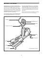
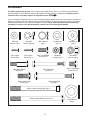
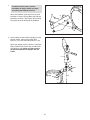
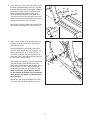
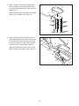
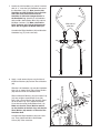
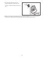
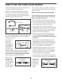
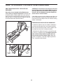
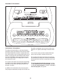
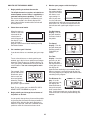
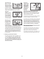
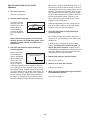
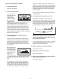
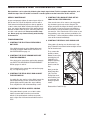
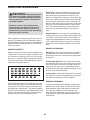
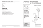
Model No. NTEL4255.0
Serial No.
Write the serial number in the space
above for reference.
USER'S MANUAL
Serial
Number
Decal
QUESTIONS?
As a manufacturer, we are committed to providing complete customer
satisfaction. If you have questions,
or if parts are damaged or missing,
PLEASE DO NOT CONTACT THE
STORE; please contact Customer
Care.
IMPORTANT: You must note the
product model number and serial
number (see the drawing above)
before contacting us:
1-888-825-2588
CALL TOLL-FREE:
Mon.–Fri. 6 a.m.–6 p.m. MST
Sat. 8 a.m.–4 p.m. MST
ON THE WEB:
www.nordictrackservice.com
CAUTION
Read all precautions and instructions in this manual before using
this equipment. Keep this manual
for future reference.
Visit our website at
www.nordictrack.com
new products, prizes,
fitness tips, and much more!
TABLE OF CONTENTS
WARNING DECAL PLACEMENT . . . . . . . . . . . . . . . . . . . . . . . . . . . . . . . . . . . . . . . . . . . . . . . . . . . . . . . . . . . . . .2
IMPORTANT PRECAUTIONS . . . . . . . . . . . . . . . . . . . . . . . . . . . . . . . . . . . . . . . . . . . . . . . . . . . . . . . . . . . . . . . .3
BEFORE YOU BEGIN . . . . . . . . . . . . . . . . . . . . . . . . . . . . . . . . . . . . . . . . . . . . . . . . . . . . . . . . . . . . . . . . . . . . . .4
ASSEMBLY . . . . . . . . . . . . . . . . . . . . . . . . . . . . . . . . . . . . . . . . . . . . . . . . . . . . . . . . . . . . . . . . . . . . . . . . . . . . . . .5
HOW TO USE THE CHEST PULSE SENSOR . . . . . . . . . . . . . . . . . . . . . . . . . . . . . . . . . . . . . . . . . . . . . . . . . . .12
HOW TO USE THE ELLIPTICAL EXERCISER . . . . . . . . . . . . . . . . . . . . . . . . . . . . . . . . . . . . . . . . . . . . . . . . . .14
MAINTENANCE AND TROUBLESHOOTING . . . . . . . . . . . . . . . . . . . . . . . . . . . . . . . . . . . . . . . . . . . . . . . . . . .22
EXERCISE GUIDELINES . . . . . . . . . . . . . . . . . . . . . . . . . . . . . . . . . . . . . . . . . . . . . . . . . . . . . . . . . . . . . . . . . . .23
PART LIST . . . . . . . . . . . . . . . . . . . . . . . . . . . . . . . . . . . . . . . . . . . . . . . . . . . . . . . . . . . . . . . . . . . . . . . . . . . . . .24
EXPLODED DRAWING . . . . . . . . . . . . . . . . . . . . . . . . . . . . . . . . . . . . . . . . . . . . . . . . . . . . . . . . . . . . . . . . . . . .25
ORDERING REPLACEMENT PARTS . . . . . . . . . . . . . . . . . . . . . . . . . . . . . . . . . . . . . . . . . . . . . . . . . .Back Cover
LIMITED WARRANTY . . . . . . . . . . . . . . . . . . . . . . . . . . . . . . . . . . . . . . . . . . . . . . . . . . . . . . . . . . . . . .Back Cover
WARNING DECAL PLACEMENT
The warning decal shown here has been applied
in the location shown. If the decal is missing or
illegible, call the telephone number on the
front cover of this manual and request a free
replacement decal. Apply the decal in the location shown. Note: The decal may not be shown
at actual size.
NordicTrack is a registered trademark of ICON IP, Inc.
2
IMPORTANT PRECAUTIONS
WARNING:
To reduce the risk of serious injury, read all important precautions and instructions in this manual and all warnings on your elliptical exerciser before using your elliptical exerciser. ICON assumes no responsibility for personal injury or property damage sustained by or
through the use of this product.
8. Wear appropriate exercise clothes while exercising; do not wear loose clothes that
could become caught on your elliptical exerciser. Always wear athletic shoes for foot
protection while exercising.
1. Before beginning any exercise program,
consult your physician. This is especially important for persons over the age of 35 or persons with pre-existing health problems.
2. It is the responsibility of the owner to ensure
that all users of the elliptical exerciser are
adequately informed of all precautions.
9. Hold the handgrip pulse sensor or the handlebars when mounting, dismounting, or using
your elliptical exerciser.
3. Your elliptical exerciser is intended for home
use only. Do not use your elliptical exerciser
in a commercial, rental, or institutional setting.
10. Keep your back straight while using your elliptical exerciser; do not arch your back.
11. The pulse sensor is not a medical device.
Various factors, including the userʼs movement, may affect the accuracy of heart rate
readings. The pulse sensor is intended only
as an exercise aid in determining heart rate
trends in general.
4. Keep your elliptical exerciser indoors, away
from moisture and dust. Place your elliptical
exerciser on a level surface, with a mat beneath it to protect the floor or carpet. Make
sure that there is enough clearance around
your elliptical exerciser to mount, dismount,
and use it.
12. When you stop exercising, allow the pedals
to slowly come to a stop.
5. Inspect and properly tighten all parts regularly. Replace any worn parts immediately.
13. If you feel pain or dizziness while exercising,
stop immediately and cool down.
6. Keep children under age 12 and pets away
from your elliptical exerciser at all times.
14. Use your elliptical exerciser only as described in this manual.
7. Your elliptical exerciser should not be used
by persons weighing more than 350 lbs.
(159 kg).
15. The battery pack contains materials that are
considered hazardous to the environment.
Proper disposal of the battery is required by
federal law.
3
BEFORE YOU BEGIN
Congratulations for selecting the new NordicTrack®
ELITE 1300 elliptical exerciser. The ELITE 1300 elliptical exerciser is an incredibly smooth exerciser that
moves your feet in a natural elliptical path, minimizing
the impact on your knees and ankles. And the ELITE
1300 elliptical exerciser offers an array of features designed to help you achieve your fitness goals in the
convenience and privacy of your home.
tions after reading this manual, please see the front
cover of this manual. To help us assist you, note the
product model number and serial number before contacting us. The model number and the location of the
serial number decal are shown on the front cover of
this manual.
Before reading further, please familiarize yourself with
the parts that are labeled in the drawing below.
For your benefit, read this manual carefully before
you use the elliptical exerciser. If you have ques-
Handlebar
Water Bottle Holder*
Console
Handgrip Pulse Sensor
Wheel
Leveling Foot
Pedal
Handle
Leveling Foot
*No water bottle is included
4
ASSEMBLY
Assembly requires two persons. Place all parts of the elliptical exerciser in a cleared area and remove the
packing materials. Do not dispose of the packing materials until assembly is completed. In addition to the in.
cluded hex keys, assembly requires an adjustable wrench
As you assemble the elliptical exerciser, use the drawings below to identify small parts. The number in parentheses
below each drawing is the key number of the part, from the PART LIST near the end of this manual. The number
following the parentheses is the quantity needed for assembly. Note: Some small parts may have been preassembled. If a part is not in the hardware kit, check to see if it has been preassembled.
M8 Small
Washer (18)–4
M10 Split
Washer (85)–20
Wave Washer
(88)–4
M10 Washer
(67)–14
M8 Washer
(69)–4
M4 x 16mm
Screw (47)–6
M4 x 19mm
Screw (57)–2
M8 x 19mm Button
Screw (56)–4
M8 Nylon
Locknut (72)–4
M10 Nylon
Locknut (70)–2
M8 x 38mm Button
Bolt (58)–4
M8 x 55mm Bolt
Set (92)–2
M10 x 25mm Patch
Screw (48)–4
M10 x 13mm Button
Screw (54)–14
M10 x 65mm Bolt
Set (94)–2
M10 x 116mm Carriage Bolt (38)–2
M10 x 123mm Button Screw (87)–2
5
Thrust Washer
(66)–4
1.
1
To make assembly easier, read the
information on page 5 before you begin
assembling the elliptical exerciser.
38
Attach the Stabilizer (8) to the Frame (1) with
two M10 x 116mm Carriage Bolts (38) and two
M10 Nylon Locknuts (70). Tighten two Leveling
Feet (36) into the underside of the Stabilizer.
8
1
36
2. Have another person hold the Upright (2) in the
position shown. Connect the Upper Wire
Harness (77) to the Lower Wire Harness (78).
70
2
Attach the Upright (2) to the Frame (1) with four
M10 x 25mm Patch Screws (48) and four M10
Split Washers (85). Make sure that no wires
are pinched between the Upright and the
Frame.
2
77
78
85
48
6
85
1
85
48
3. Attach the Track Frame (4) to the Frame (1) with
two M10 x 123mm Button Screws (87) and two
M10 Split Washers (85). Finger tighten a Button
Screw into the lower hole first, and then finger
tighten a Button Screw into the upper hole.
Then, tighten both Button Screws. Note: This
step may be easier if you raise the Frame a few
inches in the location shown by the arrow at the
right while you attach the Track Frame.
3
85
1
4
87
85
87
See the inset drawing, tighten two Leveling Feet
(36) into the underside of the Track Frame (4).
36
4. Apply a small amount of the included grease to
the sides of two Wave Washers (88) and two
Thrust Washers (66).
4
4
Slide a Weld Spacer (89) onto the Left Crank
Arm (83). Next, identify the Left Track Arm (12),
which is marked with an “L.” Orient the Left
Track Arm as shown, and slide it onto the Left
Crank Arm. Then, slide a Wave Washer (88) on
the end of the Left Crank Arm.
Grease
Slide an M8 Small Washer (18) and an Axle Cap
(41) onto an M8 x 19mm Button Screw (56).
Next, slide a Thrust Washer (66) onto the shoulder of the Axle Cap. Then, tighten the Button
Screw into the end of the Left Crank Arm (83).
Make sure that the Thrust Washer remains
on the shoulder of the Axle Cap, and that the
Wave Washer (88) remains on the end of the
Left Crank Arm.
56
Repeat this step to attach the Right Track Arm
(11) to the right side of the elliptical exerciser.
7
66 88
18 41
83
89
12
11
5. Attach a Pedal (21) to the Left Pedal Leg (14)
with seven M10 x 13mm Button Screws (54),
seven M10 Split Washers (85), and seven M10
Washers (67).
5
21
14
Attach the other Pedal (not shown) to the Right
Pedal Leg (not shown) in the same way.
67
67
85
85
54
54
6. Apply a thin film of grease to the barrel of an
M10 x 65mm Bolt Set (94). Next, fit the bracket
on the Left Pedal Leg (14) onto the bracket on
the Left Track Arm (12). Attach the Left Pedal
Leg to the Left Track Arm with the Bolt Set.
6
14
Attach the Right Pedal Leg (not shown) to the
Right Track Arm (not shown) in the same way.
Grease
94
12
8
94
7. Identify the Left Handlebar (19), which is marked
with an “L.” Insert the Left Handlebar into one of
the Handlebar Legs (17). Next, turn the Left
Handlebar and the Handlebar Leg so that the
wide side of the pivot tube on the Left
Handlebar is above the hexagonal holes in
the Handlebar Leg. Attach the Left Handlebar
with two M8 x 38mm Button Bolts (58) and two
M8 Nylon Locknuts (72). Make sure that the
Nylon Locknuts are inside of the hexagonal
holes. Do not tighten the Button Bolts yet.
7
20
19
Wide side of
pivot tube
Assemble the Right Handlebar (20) and the other
Handlebar Leg (17) in the same way.
58
Hexagonal
Holes
17
8. Apply a small amount of grease to the sides of
two Wave Washers (88) and two Thrust Washers
(66).
58
72
17
8
Slide the Left Handlebar (19) onto the Handlebar
Axle (16) as shown. Next, slide a Wave Washer
(88) onto the end of the Handlebar Axle.
20
Slide an M8 Small Washer (18) and an Axle Cap
(41) onto an M8 x 19mm Button Screw (56).
Next, slide a Thrust Washer (66) onto the shoulder of the Axle Cap. Then, tighten the Button
Screw into the end of the Handlebar Axle (16).
Make sure that the Thrust Washer remains
on the shoulder of the Axle Cap, and that the
Wave Washer (88) remains on the end of the
Handlebar Axle.
19
18
Assemble the Right Handlebar (20) in the same
way. Then, tighten both M8 x 19mm Button
Screws (56) at the same time.
56
9
66
16
88
41
Grease
66
88
1
41
56
18
9. Apply a film of grease to the barrel of an M8 x
55mm Bolt Set (92) and to a 7mm Spacer (55).
Slide an M8 Washer (69) and the Spacer onto
the barrel.
9
While another person holds the front end of the
Left Pedal Leg (14) inside of the bracket on the
left Handlebar Leg (17), insert the barrel of the
Bolt Set (92) through both parts. Next, slide a
7mm Spacer (55) and an M8 Washer (69) onto
the end of the barrel of the Bolt Set. Then, turn
the screw of the Bolt Set a few turns into the
barrel. Do not overtighten the Bolt Set; the
left Handlebar Leg must be able to pivot
freely.
Grease
Attach the right Handlebar Leg (not shown) to
the Right Pedal Leg (not shown) in the same
way.
92
See step 7. Tighten the four M8 x 38mm Button
Screws (58).
10. While another person holds the Display Console
(74) and the Control Console (75) near the
Upright (2), connect the Pulse Jumper Wire (76)
to the console pulse wire, and the Upper Wire
Harness (77) to the console wire harness. Insert
the excess wires into the Upright.
55
17
55
69
14
10
Set the Consoles (74, 75) on the Upright (2).
Attach the Consoles with six M4 x 16mm Screws
(47). Make sure that no wires are pinched. Do
not tighten the Screws yet.
47
10
74
2
47
76
69
92
75
77
11. Attach the Water Bottle Holder (26) to the
Upright (2) with two M4 x 19mm Screws (57).
11
See step 10. Tighten the six M4 x 16mm Screws
(47).
2
57
26
12. Make sure that all parts of the elliptical exerciser are properly tightened. Cover the floor beneath the elliptical exerciser to protect the floor from damage. Note: Some extra hardware may be left over.
11
HOW TO USE THE CHEST PULSE SENSOR
To get the best performance from the chest pulse sensor, please read the instructions below.
such as saliva or contact lens solution, wet both electrode areas. Then, return the sensor unit to a position
against your chest.
HOW TO PUT ON THE CHEST PULSE SENSOR
CHEST PULSE SENSOR TROUBLESHOOTING
The chest pulse sensor consists of two components:
the chest strap and the sensor unit. Follow the steps
below to put on the chest pulse sensor.
If the chest pulse sensor does not function properly, or if the displayed heart rate is excessively
high or low, try the steps below.
• Make sure that the chest pulse sensor is worn exactly as described at the left. If the chest pulse sensor does not function when positioned as described,
move it slightly lower or higher on your chest.
Chest Strap
Tab
Sensor Unit
Sensor
Unit
• Each time you use the chest pulse sensor, use
saline solution such as saliva or contact lens solution
to wet the two electrode areas on the sensor unit. If
heart rate readings do not appear until you begin
perspiring, re-wet the electrode areas.
Buckle
• Make sure that you are within armʼs length of the
console. For the console to display heart rate
readings, the user must be within armʼs length of
the console.
See the inset drawing above. Insert the tab on one end
of the chest strap through the hole in one end of the
sensor unit as shown.
Wrap the chest
pulse sensor
Logo
around your
chest. Attach the
free end of the
chest strap to the
sensor unit as
described above.
Adjust the length of the chest strap, if necessary. The
chest pulse sensor should be under your clothing,
against your skin, and as high under the pectoral muscles or breasts as is comfortable. Make sure that the
logo is facing forward and is right-side-up.
Pull the sensor
unit away from
your body a few
inches and locate
the two electrode
areas on the
inner side. Using
a saline solution
• The chest pulse sensor is designed to work with
people who have normal heart rhythms. Heart rate
reading problems may be caused by medical conditions such as premature ventricular contractions
(pvcs), tachycardia bursts, and arrhythmia.
• The operation of the chest pulse sensor can be affected by magnetic interference caused by high
power lines or other sources. If it is suspected that
magnetic interference may be causing a problem,
try relocating your exercise equipment.
• If the chest pulse sensor still does not function properly, test the chest pulse sensor in the following way:
Hold the chest
pulse sensor
and place your
thumbs over
the electrode
areas as
shown.
Electrode Areas
12
Electrode Areas
CHEST PULSE SENSOR CARE
Next, hold the chest pulse sensor near the console.
While holding one thumb stationary, begin tapping
the other thumb against the electrode area at a rate
of about one tap per second. Check the heart rate
reading on the console.
• Thoroughly dry the chest pulse sensor after each
use. The chest pulse sensor is activated when the
electrode areas are wetted and the chest pulse sensor is put on; the chest pulse sensor shuts off when
it is removed and the electrode areas are dried. If
the chest pulse sensor is not dried after each use, it
may remain activated longer than necessary, draining the battery prematurely.
• If the chest pulse sensor does not function properly
after you have followed all of the above instructions,
replace the battery in the following way:
Locate the battery
cover on the back of
the sensor unit. Insert
a coin into the slot in
the cover, turn the
cover counterclockwise, and remove the
cover.
Remove the old battery and insert a new
CR 2032 battery.
Make sure that the
battery is turned so
the writing is on
top. Reattach the
battery cover and
turn it clockwise to
close it.
• Store the chest pulse sensor in a warm, dry place.
Do not store the chest pulse sensor in a plastic bag
or other container that may trap moisture.
• Do not expose the chest pulse sensor to direct sunlight for extended periods of time. Do not expose the
chest pulse sensor to temperatures above 122°
Fahrenheit (50° Celsius) or below 14° Fahrenheit
(-10° Celsius).
• Do not excessively bend or stretch the sensor unit
when using or storing the chest pulse sensor.
CR 2032
Battery
• Clean the sensor unit using a damp cloth—never
use alcohol, abrasives, or chemicals. The chest
strap may be hand washed and air dried.
13
HOW TO OPERATE THE ELLIPTICAL EXERCISER
CAUTION: To decrease the risk of injury, bend your
legs and keep your back straight. Make sure to use
your legs rather than your back to lift the elliptical
exerciser. Do not attempt to move the elliptical exerciser over an uneven surface.
HOW TO MOVE AND LEVEL THE ELLIPTICAL
EXERCISER
Due to the size and weight of the elliptical exerciser, moving it requires two persons. With the help
of another person, lift the handle on the rear of the elliptical exerciser until the elliptical exerciser will roll on
the front wheels. Carefully move the elliptical exerciser
to the desired location and then lower it.
If the elliptical exerciser rocks slightly on your floor, see
the inset drawings and turn the leveling feet under the
front and rear of the elliptical exerciser until the rocking
motion is eliminated.
EXERCISING ON THE ELLIPTICAL EXERCISER
To mount the elliptical exerciser, hold the handlebars
and step onto the pedal that is in the lowest position.
Next, step onto the other pedal. Push the pedals until
they begin to move with a continuous motion.
Wheel
To dismount the elliptical exerciser, wait until the pedals come to a complete stop. The elliptical exerciser
does not have a free wheel; the pedals will continue to move until the flywheel stops. When the
pedals are stationary, step off the highest pedal first.
Then, step off the lowest pedal.
Lift
Here
Leveling
Feet
Leveling
Foot
14
DIAGRAM OF THE CONSOLE
FEATURES OF THE CONSOLE
the pedals and prompts you to increase or decrease
your pace as it guides you through an effective workout.
The advanced console offers a selection of features
designed to make your workouts more effective. When
the manual mode of the console is selected, the resistance of the pedals can be changed with the touch of a
button. As you pedal, the console will provide continuous exercise feedback. You can even measure your
heart rate using the built-in handgrip pulse sensor or
the chest pulse sensor.
You can even create your own custom workout programs and save them in memory for future use.
The console also features three heart rate programs
that automatically change the resistance of the pedals
to keep your heart rate near a target heart rate as you
exercise.
The console also features personal goal programming
that allows you to choose a goal for your workout. As
you exercise, the console will display feedback until
the goal is reached.
To use the manual mode of the console, see page
16. To create and use a custom program, see page
18. To use a preset program, see page 19. To use a
heart rate program, see page 20.
In addition, the console offers nine preset programs.
Each program automatically changes the resistance of
15
HOW TO USE THE MANUAL MODE
1.
2.
3.
5.
Begin pedaling to activate the console.
The elliptical exerciser requires no batteries or
external power source. Power is supplied by a
generator while you are pedaling. To activate
the console, begin pedaling at a moderate pace.
After a few seconds, the console displays will
light. A tone will then sound and the console will
be ready for use.
Select the manual mode.
The matrix—When
the manual mode is
selected, the matrix
will show a track
representing 1/4
mile. As you exercise, the indicators
around the track will light in succession until the
entire track is lit. The track will then darken and
the indicators will again begin to light in succession.
The Resistance
display—This display will show the
resistance level of
the pedals.
When the power is
turned on, the manual mode will be
selected and a
track will appear in
the display. If you
have selected a
program, reselect the manual mode by pressing
the Manual button.
The Speed
display—This display will show your
pedaling speed, in
revolutions per
minute.
Set a workout goal if desired.
If you do not wish to set a workout goal, go to step
4.
The Time
display—If no time
goal was set, this
display will show
the elapsed time. If
a time goal was set,
the display will
show the time remaining in your workout. Note:
When a program is selected (except for the first
heart rate program), the display will show the time
remaining in the program.
To set a time, distance, or calorie goal for your
workout, press the increase and decrease buttons
below the Time, Distance, or Calories display. To
set a goal quickly, hold down the increase and decrease buttons. You can set one goal for each
workout.
For example, if you
plan to exercise for
30 minutes, press
the increase and
decrease buttons
below the Time display until the display shows a goal of “30:00.”
4.
Monitor your progress with the displays.
The Distance display—If no distance goal was set,
this display will
show the distance
that you have pedaled, in total revolutions. If a distance goal was set, the display will
show the distance still to be pedaled during your
workout.
Note: To set a pulse goal, see HOW TO USE A
HEART RATE PROGRAM on page 20.
Begin pedaling and change the resistance of
the pedals as desired.
As you pedal, change the resistance of the pedals
by pressing the One-touch Resistance buttons if
desired. Note: After the One-touch Resistance
buttons are pressed, it will take a moment for the
pedals to reach the selected resistance level.
16
The Calories display—If no calorie
goal was set, this
display will show the
approximate number
of calories you have
burned. If a calories
goal was set, the display will show the number of
calories still to be burned during your workout.
If there are
sheets of clear
plastic on the
metal contacts
on the handContacts
grip pulse sensor, peel off
the plastic.
Place your
hands on the handgrip pulse sensor, with your
palms on the contacts. Avoid moving your
hands. When your pulse is detected, one or two
dashes will appear in the Pulse display and then
your heart rate will be shown.
The Pulse
display—This display will show your
heart rate when you
use the handgrip
pulse sensor or the
chest pulse sensor
(see step 6 below).
For the most accurate heart rate reading, continue
to hold the handgrips for about 30 seconds.
If your heart rate is not shown, make sure that your
hands are positioned as described. Avoid moving
your hands excessively or squeezing the metal
contacts too tightly. For optimal performance, periodically clean the metal contacts using a soft cloth;
never use alcohol, abrasives, or chemicals.
Note: You can select any of three
backlight modes for
the displays. The
“On” mode keeps
the backlight on
while the console is
on. The “Off” mode turns the backlight off. The
“Auto” mode keeps the backlight on only while you
are exercising. To change the backlight mode, first
hold down the Start button for a few seconds. The
current backlight mode will appear in the Calories
display. Next, press the One-touch Resistance 1
button to change the backlight mode. Then, press
the Start button.
7. When you are finished exercising, the console
will automatically turn off.
If the pedals are not moved for a few seconds, a
series of tones will sound, the Time display will
begin to flash, and the console will pause.
If the pedals are not moved for a few minutes, the
console will turn off and the displays will be reset.
6. Measure your heart rate if desired.
To use the chest pulse sensor, see page 12. To
use the handgrip pulse sensor, follow the instructions below. Note: If you wear the chest pulse
sensor and hold the handgrip pulse sensor at
the same time, the console will not display your
heart rate accurately.
17
HOW TO CREATE AND USE A CUSTOM
PROGRAM
When the first segment of the program ends, a series of tones will sound and the current resistance
setting and the current pace setting will be saved in
memory. The columns of indicators will then move
one column to the left, and the resistance setting
for the second segment will be shown in the flashing Current Segment column. Program a resistance setting and a pace setting for the second
segment as described above.
1. Turn on the console.
See step 1 on page 16.
2. Select a custom program.
To select a custom
program, press one
of the three Custom
buttons. When a
Custom button is
pressed, the indicator on the button will
light.
Continue programming resistance and pace settings for as many segments as desired; custom
programs can have up to 40 segments.
4. Press the Start button or begin pedaling to
start the program.
The custom program will function in almost the
same way as a preset program (see steps 3 and 4
on page 19).
Note: If the custom program has not yet been
defined, see step 3 to create the program. If the
program is already defined, see step 4 to use
the program.
If desired, you can redefine the program while
using it. To change the resistance or pace setting for the current segment, simply press the
One-touch Resistance buttons or change your pedaling pace. When the current segment ends, the
new setting will be saved in memory.
3. Press the Start button or begin pedaling to
start the program.
Refer to the matrix.
Each custom proCurrent Segment
gram is divided into
40 one-minute segments. One resistance setting and
one pace setting
can be programmed for each segment. The resistance setting for the first segment will be shown in
the flashing Current Segment column of the matrix.
(The pace settings are not shown in the matrix.) To
program a resistance setting and a pace setting for
the first segment, simply adjust the resistance of
the pedals as desired by pressing the One-touch
Resistance buttons and pedal at the desired pace.
5. Monitor your progress with the displays.
See step 5 on page 16.
6. Measure your heart rate if desired.
See step 6 on page 17.
7. When you are finished exercising, the console
will automatically turn off.
See step 7 on page 17.
18
HOW TO USE A PRESET PROGRAM
resistance settings will move one column to the
left. The resistance setting for the second segment
will then be shown in the flashing Current Segment
column and the resistance of the pedals will automatically change to the resistance setting for the
second segment.
1. Turn on the console.
See step 1 on page 16.
2. Select a preset program.
The program will continue until no time remains in
the Time display.
To select a preset
program, press one
of the Aerobic,
Performance, or
Endurance buttons.
When an Aerobic,
Performance, or
Endurance button is pressed, the indicator on the
button will light. When a preset program is selected, a profile of the first several resistance settings of the program will appear in the matrix, the
program time will appear in the Time display, the
maximum resistance setting of the program will
flash in the Resistance display, and the maximum
speed setting of the program will flash in the Speed
display for a few seconds.
4. Use the pace guide to pace your exercise.
Throughout the program, the pace guide will
prompt you to increase or decrease your pedaling
pace. When one of the “Too Slow” indicators lights,
increase your pace; when one of the “Too Fast” indicators lights, decrease your pace. When the center indicator lights, maintain your current pace.
3. Press the Start button or begin pedaling to
start the program.
IMPORTANT: The pace guide is intended only
to provide a goal. Make sure to pedal at a pace
that is comfortable for you.
Each program is divided into either 20 or 30 oneminute segments. One resistance setting and one
pace setting are programmed for each segment.
Note: The same resistance setting and/or target
pace may be programmed for two or more consecutive segments.
If you stop pedaling for several seconds, a tone will
sound and the program will pause. To restart the
program, simply resume pedaling.
5. Monitor your progress with the displays.
When you start the
program, the resisCurrent Segment
tance setting for the
first segment will be
shown in the flashing Current
Segment column of
the matrix. The resistance settings for the next several segments will be shown in the columns to the
right.
See step 5 on page 16.
6. Measure your heart rate if desired.
See step 6 on page 17.
7. When you are finished exercising, the console
will automatically turn off.
See step 7 on page 17.
When only three seconds remain in the first segment of the program, both the Current Segment
column and the column to the right will flash, a series of tones will sound, and the time will flash in
the Time display. When the first segment ends, all
19
HOW TO USE A HEART RATE PROGRAM
4. Put on the chest pulse sensor or hold the handgrip pulse sensor.
1. Turn on the console.
To use a heart rate program, you must wear the
chest pulse sensor or use the handgrip pulse sensor. If you use the handgrip pulse sensor, it is not
necessary to hold the handgrips continuously during the program; however, you should hold the
handgrips frequently for the program to operate
properly. Each time you hold the handgrips,
keep your hands on the metal contacts for at
least 30 seconds. Note: When you are not holding
the handgrips, the letters “PLS” will flash in the
Pulse display instead of your heart rate.
See step 1 on page 16.
2. Select a heart rate program.
To select a heart
rate program, press
one of the three
Heart Rate buttons.
When a Heart Rate
button is pressed,
the indicator on the
button will light.
5. Press the Start button to start the program.
If the first heart
rate program is selected, a pulse symbol will appear in the
matrix.
The first heart rate program—This program is divided into 100 one-minute segments. The same
target heart rate setting is programmed for all segments. Note: For a shorter workout, stop exercising
or select a different program before the program
ends.
If the second or
third heart rate
program is selected, a profile of
the first several target heart rate settings of the program
will appear in the matrix.
The second and third heart rate programs—
These programs are divided into 30 one-minute
segments. One target heart rate setting is programmed for each segment. Note: The same target heart rate setting may be programmed for two
or more consecutive segments.
The target heart rate
Current Segment
setting for the first
segment will be
shown in the flashing Current Segment
column of the matrix. The target heart
rate settings for the next several segments will be
shown in the columns to the right.
3. Enter a target heart rate setting.
If the first heart rate program is selected, the
target heart rate setting for the program will flash in
the Pulse display. If desired, press the increase
and decrease buttons below the Pulse display to
change the target heart rate setting (see EXERCISE INTENSITY on page 23). Note: The same
target heart rate setting will be programmed for all
segments.
When only three seconds remain in the first segment of the program, both the Current Segment
column and the column to the right will flash, a series of tones will sound, and all target heart rate
settings will move one column to the left. The target heart rate setting for the second segment will
then be shown in the flashing Current Segment
column.
If the second or third heart rate program is selected, the maximum target heart rate setting of
the program will flash in the Pulse display. If desired, press the increase and decrease buttons
below the Pulse display to change the maximum
target heart rate setting (see EXERCISE INTENSITY on page 23). Note: If the maximum target
heart rate setting is changed, the intensity level of
the entire program will change.
20
Both heart rate programs—As you pedal, the
console will regularly compare your heart rate to
the target heart rate setting. If your heart rate is too
far below or above the target heart rate setting, the
resistance of the pedals will automatically increase
or decrease to bring your heart rate closer to the
target heart rate setting.
Note: During the program, you can manually override the resistance setting for the current segment,
if desired, with the One-touch Resistance buttons.
However, when the console compares your heart
rate to the target heart rate setting, the resistance
of the pedals may automatically increase or decrease to bring your heart rate closer to the target
heart rate setting.
After the first segment ends, the pace guide will
prompt you to maintain a constant pedaling pace.
When one of the “Too Slow” indicators lights, increase your pace; when one of the “Too Fast” indicators lights, decrease your pace. When the center
indicator lights, maintain your current pace.
If you stop pedaling for several seconds, a tone will
sound and the program will pause. To restart the
program, simply resume pedaling.
6. Monitor your progress with the displays.
See step 5 on page 16.
7. When the program is finished, the console will
automatically turn off.
See step 7 on page 17.
IMPORTANT: The target heart rate settings are
intended only to provide motivation. Make sure
to exercise at a pace that is comfortable for
you.
21
MAINTENANCE AND TROUBLESHOOTING
Most problems can be solved by following the simple steps below. Find the symptom that applies, and
follow the steps listed. If further assistance is needed, please see the front cover of this manual.
WEEKLY MAINTENANCE
5. SYMPTOM: THE CONSOLE TURNS OFF AS
SOON AS YOU STOP PEDALING
Inspect and properly tighten all external parts of the elliptical exerciser. Clean the elliptical exerciser with a
small amount of mild multi-purpose cleaner applied to
a 100% cotton cloth. When cleaning the elliptical exerciser, pay special attention to the track and the wheels.
Remove all debris from the track. Clean the pedal covers with a soft nylon brush. Do not use acidic cleaners. Never spray any cleaner directly onto the elliptical exerciser.
If the console turns off as soon as you stop pedaling, the battery pack may not be charged. The
longer you pedal, the longer the battery pack will retain a charge. It may be necessary to pedal for a
few minutes to charge the battery pack each time
you exercise. If the console turns off as soon as you
stop pedaling, even after you have pedaled for several minutes, call the telephone number on the front
cover of this manual immediately.
TROUBLESHOOTING
6. SYMPTOM: THE PEDALS SLIP DURING USE
1. SYMPTOM: THE ELLIPTICAL EXERCISER IS
NOT LEVEL
If the pedals slip during use, the drive belt is slipping. Follow the instructions below to adjust the tension of the drive belt.
If the elliptical exerciser rocks slightly during use,
see HOW TO MOVE AND LEVEL THE ELLIPTICAL EXERCISER on page 14.
First, remove the
two M6 x 16mm
Button Screws (49)
attaching the left
Pedal Disc (5).
Without removing
the Pedal Disc,
pivot it out of the
way.
2. SYMPTOM: THE PULSE SENSOR DOES NOT
FUNCTION PROPERLY
If the chest pulse sensor does not function properly,
see CHEST PULSE SENSOR TROUBLESHOOTING on pages 12 and 13.
If the handgrip pulse sensor does not function properly, see step 6 on page 17.
Next, locate the
M10 Flange Nut
(95). Turn the
Flange Nut clockwise until the pedals no longer slip
during the power
stroke.
3. SYMPTOM: THE PEDAL DISCS RUB AGAINST
THE SIDE SHIELDS
If a pedal disc rubs against a side shield, loosen the
side shield mounting screws and move the side
shield slightly until the pedal disc stops rubbing.
Then, retighten the side shield mounting screws.
5
49
Reattach the Pedal Disc (5).
4. SYMPTOM: THE PEDAL WHEELS SQUEAK
If the pedal wheels squeak, use a 100% cotton
cloth to remove debris from the track and the
wheels. If the pedal wheels continue to squeak,
apply a light coat of silicone-based lubricant to the
track.
22
95
EXERCISE GUIDELINES
WARNING:
Burning Fat—To burn fat effectively, you must exercise at a low intensity level for a sustained period of
time. During the first few minutes of exercise, your
body uses carbohydrate calories for energy. Only after
the first few minutes of exercise does your body begin
to use stored fat calories for energy. If your goal is to
burn fat, adjust the intensity of your exercise until your
heart rate is near the lowest number in your training
zone. For maximum fat burning, exercise with your
heart rate near the middle number in your training
zone.
Before beginning this
or any exercise program, consult your physician. This is especially important for persons
over the age of 35 or persons with pre-existing health problems.
The pulse sensor is not a medical device.
Various factors may affect the accuracy of
heart rate readings. The pulse sensor is intended only as an exercise aid in determining
heart rate trends in general.
Aerobic Exercise—If your goal is to strengthen your
cardiovascular system, you must perform aerobic exercise, which is activity that requires large amounts of
oxygen for prolonged periods of time. For aerobic exercise, adjust the intensity of your exercise until your
heart rate is near the highest number in your training
zone.
These guidelines will help you to plan your exercise
program. For detailed exercise information, obtain a
reputable book or consult your physician. Remember,
proper nutrition and adequate rest are essential for
successful results.
WORKOUT GUIDELINES
EXERCISE INTENSITY
Warming up—Start with 5 to 10 minutes of stretching
and light exercise. A warm-up increases your body
temperature, heart rate, and circulation in preparation
for exercise.
Whether your goal is to burn fat or to strengthen your
cardiovascular system, exercising at the proper intensity is the key to achieving results. You can use your
heart rate as a guide to find the proper intensity level.
The chart below shows recommended heart rates for
fat burning and aerobic exercise.
Training Zone Exercise—Exercise for 20 to 30 minutes with your heart rate in your training zone. (During
the first few weeks of your exercise program, do not
keep your heart rate in your training zone for longer
than 20 minutes.) Breathe regularly and deeply as you
exercise–never hold your breath.
Cooling down—Finish with 5 to 10 minutes of stretching. Stretching increases the flexibility of your muscles
and helps to prevent post-exercise problems.
EXERCISE FREQUENCY
To find the proper intensity level, find your age at the
bottom of the chart (ages are rounded off to the nearest ten years). The three numbers listed above your
age define your “training zone.” The lowest number is
the heart rate for fat burning, the middle number is the
heart rate for maximum fat burning, and the highest
number is the heart rate for aerobic exercise.
To maintain or improve your condition, complete three
workouts each week, with at least one day of rest between workouts. After a few months of regular exercise, you may complete up to five workouts each
week, if desired. Remember, the key to success is to
make exercise a regular and enjoyable part of your
everyday life.
23
PART LIST—Model No. NTEL4255.0
Key No. Qty.
1
2
3
4
5
6
7
8
9
10
11
12
13
14
15
16
17
18
19
20
21
22
23
24
25
26
27
28
29
30
31
32
33
34
35
36
37
38
39
40
41
42
43
44
45
46
47
48
49
50
1
1
2
1
2
1
1
1
1
1
1
1
1
1
1
1
2
4
1
1
2
2
2
10
1
1
4
2
1
1
4
1
2
10
4
4
4
2
2
4
4
12
1
1
2
4
8
4
8
2
Description
Key No. Qty.
Frame
Upright
Track
Track Frame
Pedal Disc
Left Side Shield
Right Side Shield
Stabilizer
Crank
Crank Spacer
Right Track Arm
Left Track Arm
Right Pedal Leg
Left Pedal Leg
Drive Belt
Handlebar Axle
Handlebar Leg
M8 Small Washer
Left Handlebar
Right Handlebar
Pedal
Transport Wheel
Handlebar Foam
Plastic Insert
Pulley
Water Bottle Holder
6mm Spacer
Set Screw
Idler
Generator
Wheel
Control Board
Pulse Grip
Bearing Cradle
Endcap
Leveling Foot
M6 Split Washer
M10 x 116mm Carriage Bolt
Handlebar Cap
Ramp Screw
Axle Cap
Bearing
Controller Bracket
Short Crank Spacer
Snap Ring
Wheel Bushing
M4 x 16mm Screw
M10 x 25mm Patch Screw
M6 x 16mm Button Screw
M8 x 56mm Button Screw
51
52
53
54
55
56
57
58
59
60
61
62
63
64
65
66
67
68
69
70
71
72
73
74
75
76
77
78
79
80
81
82
83
84
85
86
87
88
89
90
91
92
93
94
95
96
*
*
*
4
8
2
14
4
4
2
4
20
4
2
2
8
4
2
4
14
1
12
2
1
15
1
1
1
1
1
1
1
1
1
1
1
1
20
4
2
4
3
4
12
2
2
2
1
4
–
–
–
Description
R0509A
Crank Screw
Stand Off
M6 x 12mm Button Screw
M10 x 13mm Button Screw
7mm Spacer
M8 x 19mm Button Screw
M4 x 19mm Screw
M8 x 38mm Button Bolt
M5 x 16mm Screw
16mm Spacer
M8 x 48mm Bolt
3mm Spacer
Pedal Bushing
Long Side Shield Spacer
Key
Thrust Washer
M10 Washer
Battery Pack
M8 Washer
M10 Nylon Locknut
Tension Bolt
M8 Nylon Locknut
Short Side Shield Spacer
Display Console
Control Console
Pulse Jumper Wire
Upper Wire Harness
Lower Wire Harness
Controller Wire Harness
Ground Wire
Generator Coil Wire
Electromagnet Wire
Left Crank Arm
Right Crank Arm
M10 Split Washer
M8 Split Washer
M10 x 123mm Button Screw
Wave Washer
Weld Spacer
Small Bearing Cradle
Small Bearing
M8 x 55mm Bolt Set
Wheel Bolt
M10 x 65mm Bolt Set
M10 Flange Nut
M6 Washer
Userʼs Manual
Hex Key
Grease Packet
Note: Specifications are subject to change without notice. See the back cover of this manual for information about
ordering replacement parts. *These parts are not illustrated.
24
EXPLODED DRAWING A—Model No. NTEL4255.0
74
57
75
26
47
47
47
47
2
47
24
33
34
33
42 34
96
70
69
71
22 46
46
50
24
37
24
35
27
95
72 69
69
27
22 46
46
8
27
69
27
35
40
52
32
47
52
78
52
76
79
80
81
82
1
40
3
85 87
4
43
24
70
96
50
24
52
47
77
24
30
72
68
85
49
37
48
85
45
16
42
85
45 85
48
38
29
R0509A
15
40
87
35
3
36
35
25
40
36
EXPLODED DRAWING B—Model No. NTEL4255.0
5
59
59
64
64
59
59
49
59
59
59
53
73
6
5
7
53
59
26
49
R0509A
EXPLODED DRAWING C—Model No. NTEL4255.0
39
19
41
18
56
88
66
42
34
34
89
41
18
56
88
66
69
42
42
55 69 92
34
65
61
72
23
34
61
28
72
10
51
89
34
34
42
51 86
28
44
42
20
42
34
42
72
89
84
92
23
42
17
55
39
72
58
65
25
9
42
66
88
92
58
18
69
55
90
90
91
72
55
91
72
63
90
63
93
69
60
21
13
63
72
91
27
69
72
91
91
31
91
62
60 31
69
93
91
67
60
91 31
54
85
54
21
94
69
91
62
56
94
14
63
41
18
94
91
90 91
88
92
11
86
91
69
66
34
17
56
41
83
12
R0509A
31
60
54
94
67
85
54
67
85
54
ORDERING REPLACEMENT PARTS
To order replacement parts, please see the front cover of this manual. To help us assist you, be prepared to
provide the following information when contacting us:
• the model number and serial number of the product (see the front cover of this manual)
• the name of the product (see the front cover of this manual)
• the key number and description of the replacement part(s) (see the PART LIST and the EXPLODED
DRAWING near the end of this manual)
LIMITED WARRANTY
ICON Health & Fitness, Inc. (ICON) warrants this product to be free from defects in workmanship and
material, under normal use and service conditions, for a period of one (1) year from the date of purchase. This warranty extends only to the original purchaser. ICON's obligation under this warranty is limited to replacing or repairing, at ICON's option, the product through one of its authorized service centers.
All repairs for which warranty claims are made must be pre-authorized by ICON. If the product is shipped
to a service center, freight charges to and from the service center will be the customerʼs responsibility.
For in-home service, the customer will be responsible for a minimal trip charge. This warranty does not
extend to any product or damage to a product caused by or attributable to freight damage, abuse, misuse, improper or abnormal usage or repairs not provided by an ICON authorized service center; products used for commercial or rental purposes; or products used as store display models. No other warranty beyond that specifically set forth above is authorized by ICON.
ICON is not responsible or liable for indirect, special or consequential damages arising out of or in connection with the use or performance of the product or damages with respect to any economic loss, loss
of property, loss of revenues or profits, loss of enjoyment or use, costs of removal or installation or other
consequential damages of whatsoever nature. Some states do not allow the exclusion or limitation of incidental or consequential damages. Accordingly, the above limitation may not apply to you.
The warranty extended hereunder is in lieu of any and all other warranties and any implied warranties of
merchantability or fitness for a particular purpose is limited in its scope and duration to the terms set
forth herein. Some states do not allow limitations on how long an implied warranty lasts. Accordingly, the
above limitation may not apply to you.
This warranty gives you specific legal rights. You may also have other rights which vary from state to
state.
ICON HEALTH & FITNESS, INC., 1500 S. 1000 W., LOGAN, UT 84321-9813
Part No. 235685 R0509A
Printed in USA © 2008 ICON IP, Inc.