1
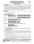
10/100/1000BaseT to Mini-GBIC Industrial Media Converter User Manual Content Overview ............................................................ 1 Introduction .............................................................. 1 Features ................................................................... 3 Packing List .............................................................. 4 Safety Precaution ..................................................... 4 Hardware Description......................................... 5 Front Panel ............................................................... 5 Top View .................................................................. 6 Wiring the Power Inputs ........................................... 6 Wiring the Fault Alarm Contact ................................ 7 LED Indicators .......................................................... 8 DIP-Switch ............................................................... 9 Ports ....................................................................... 10 Cabling ................................................................... 11 Mounting Installation ........................................ 15 DIN-Rail Mounting .................................................. 15 Wall Mount Plate Mounting .................................... 17 Hardware Installation ....................................... 18 Installation Steps .................................................... 18 Troubles shooting............................................. 20 Technical Specification .................................... 21 FCC Warning This Equipment has been tested and found to comply with the limits for a Class-A digital device, pursuant to Part 15 of the FCC rules. These limits are designed to provide reasonable protection against harmful interference in a residential installation. This equipment generates, uses, and can radiate radio frequency energy. It may cause harmful interference to radio communications if the equipment is not installed and used in accordance with the instructions. However, there is no guarantee that interference will not occur in a particular installation. If this equipment does cause harmful interference to radio or television reception, which can be determined by turning the equipment off and on, the user is encouraged to try to correct the interference by one or more of the following measures: Reorient or relocate the receiving antenna. Increase the separation between the equipment and receiver. Connect the equipment into an outlet on a circuit different from that to which the receiver is connected. Consult the dealer or an experienced radio/TV technician for help. CE Mark Warning This is a Class-A product. In a domestic environment this product may cause radio interference in which case the user may be required to take adequate measures. Overview Introduction The 10/100/1000TX to MINI-GBIC is designed to convert Gigabit Ethernet networks to Gigabit fiber networks by transparently converting Ethernet signals to optic signals. The advantages of fiber optics are wide bandwidth, EMI immunity and long-distance transmission capability. Therefore, the industrial switch converter is an ideal solution for “fiber to building” applications at central offices or local sites. The industrial switch converter supports MDI/MDIX auto detection, so you don’t need to use crossover wires. Furthermore, the industrial switch converter can work normally from -10 ~ 60o C and accepts a wide voltage range from +12 ~ 48 VDC. Besides, it also provides 3,000 VDC surge (EFT) protection against over-voltage, so it is suitable for harsh operating environments. Gigabit Fiber Converter The 10/100/1000TX to MINI-GBIC Industrial Switch Converter has one SFP fiber slot which provides the flexibility when planning and implementing a network. The slot can accept any 1000M SFP-type fiber module and these modules are designed for transmitting over distances of either 500m (multi-mode), 10km, 30km, 50km, 70km or 110km (single-mode). This means you can easily change the transmission mode and distance of the switch by simply pulling out the SFP module and plugging in a different module. The SFP module is hot-swappable and plug-and-play! Dual Power Input To reduce the risk of power failure, the 10/100/1000TX to MINI-GBIC Industrial Switch Converter provides +12 ~ 48 VDC dual power inputs. If there is power failure, 10/100/1000TX to MINI-GBIC Industrial Switch Converter will switch automatically to the secondary power input. 1 Flexible Mounting 10/100/1000TX to MINI-GBIC Industrial Switch Converter is compact and can be mounted on a DIN-rail or a panel, so it is suitable for any space-constrained environment. Advanced Protection The power line of 10/100/1000TX to MINI-GBIC Industrial Switch Converter supports up to 3,000 VDC EFT protection, which secure equipment against unregulated voltage and make systems safer and more reliable. Meanwhile, 6,000 VDC ESD protections for Ethernet ports make the industrial switch converter more suitable for harsh environments. Wide Operating Temperature The operating temperature of the 10/100/1000TX to MINI-GBIC Industrial Switch Converter is between -40 ~ 75 oC (wide operating temperature model) or -10 ~ 60 oC (standard model). With such a wide range, you can use the industrial switch converter in some of the harshest industrial environments that exist. Easy Troubleshooting LED indicators make troubleshooting quick and easy. The 10/100/1000 Base-TX port has 2 LEDs that display the link status, whether the port is working at 1000M transmission speed or not. Also the three power indicators P1, P2 and Fault help you diagnose immediately. 2 Features Provides 1 x SFP (mini-GBIC) type socket Provides 1 x 10/100/1000Mbps Ethernet ports with RJ-45 connector Supports full/half duplex flow control Supports MDI/MDI-X auto-crossover Supports surge (EFT) protection 3,000 VDC for power line Supports 6,000 VDC Ethernet ESD protection Embedded with a switch controller, supports auto-negotiation Supports store & forward transmission Supports redundant +12 ~ 48 VDC power input Provides flexible mounting: DIN-rail, Wall Mounting Supports operating temperatures from -40 ~ 75oC (wide operating temperature model) or -10 ~ 60oC (standard model) 3 Packing List 1 x 10/100/1000 to Mini-GBIC Industrial Switch Converter 1 x User manual 2 x Wall Mounting Bracket and Screws Safety Precaution Attention IF DC voltage is supplied by an external circuit, please use a protection device on the power supply input. 4 Hardware Description In this paragraph, we will introduce the Industrial switch converter’s hardware spec, port, cabling information, and wiring installation. Front Panel The Front Panel of the 10/100/1000TX to MINI-GBIC Industrial Switch Converter are shown as below. Front Panel of the Industrial Switch Converter 5 Top View The top panel of the Industrial Switch Converter is equipped one terminal block connector of two DC power inputs. Top panel of the Industrial Switch Converter Wiring the Power Inputs Please follow the steps below to insert the power wire. 1. Insert the positive and negative wires into the V+ and V- contacts on the terminal block connector. 6 2. To tighten the wire-clamp screws for preventing the DC wires to loose. Wiring the Fault Alarm Contact The fault alarm contact is in the middle of terminal block connector as the picture shows below. Inserting the wires, it will detect the fault status which the power is failure or port link failure (for managed model) and form an open circuit. Insert the wires into the fault alarm contact (No. 3 & 4) Note The wire gauge for the terminal block should be in the range between 12~ 24 AWG. If only using one power source, jumper Pin 1 to Pin 5 and Pin 2 to Pin 6 to eliminate power fault alarm. 7 LED Indicators There are few LEDs display the power status and network status located on the front panel of the Industrial switch converter, each of them has its own specific meaning as below table. Table 2.1: Industrial Switch Converter LED Definition LED Color P1 Green P2 Green Fault LNK/ACT (fiber port) 1000M (RJ-45) LNK/ACT (RJ-45) Red Green Yellow Green Description On Power input 1 is active Off Power input 1 is inactive On Power input 2 is active Off Power input 2 is inactive On Power input 1 or 2 has failed Off Power input 1 and 2 are both functional, or no power input On Connected to network Flashing Networking is active Off Not connected to network On Link to 1000M bps network Off Not connected to network or not working at speed of 1000M On Connected to network Flashing Networking is active Off Not connected to network 8 DIP-Switch The DIP-Switch is used to configure operation mode for LLF (Link Lost Forwarding) and power alarm. The default value of DIP-switch is OFF. Table 2.2: Industrial Switch Converter DIP-Switch Definition S/W No Status 1 2 Description ON Enable Power Alarm OFF Disable Power Alarm ON Enables LLF OFF Disables LLF Link Lost Forwarding (DIP-Switch 2): When LLF is enabled, it allows UTP link failures to be reported to the fiber side and also allows Fiber link failures to be reported to the UTP side. Therefore, a link loss forwarding feature is provided in both UTP and Fiber side. Note When SW 2 is on, once the fiber or UTP/STP cable is disconnected, the LNK/ACT LED off. When the cable is reconnected, the LNK/ACT LED blinks for 2 ~ 6 seconds which means the connection is recovering from failure. Note Please don’t change the DIP-switch setting when UTP/STP or fiber port is transmitting or receiving data. It may cause some data error. Besides, if you change the DIP-switch setting, please power off the converter and power on again to make the setting effective. 9 Ports RJ-45 ports (Auto MDI/MDIX): The RJ-45 ports are auto-sensing for 10Base-T, 100Base-TX or 1000Base-T devices connections. Auto MDI/MDIX means that you can connect to another switch or workstation without changing straight through or crossover cabling. See figures as below for straight through and crossover cable schematic. Note RJ-45 Pin Assignments Pin Number Assignment 1 Tx+ 2 Tx- 3 Rx+ 6 Rx- “+” and “-” signs represent the polarity of the wires that make up each wire pair. All ports on this industrial switch converter support automatic MDI/MDI-X operation, you can use straight-through cables (See Figure below) for all network connections to PCs or servers, or to other switches or hubs. In straight-through cable, pins 1, 2, 3, and 6, at one end of the cable, are connected straight through to pins 1, 2, 3 and 6 at the other end of the cable. The table below shows the 10BASE-T/ 100BASE-TX /1000Base-T MDI and MDI-X port pin outs. Pin MDI-X Signal Name MDI Signal Name 1 Receive Data plus (RD+) Transmit Data plus (TD+) 2 Receive Data minus (RD-) Transmit Data minus (TD-) 3 Transmit Data plus (TD+) Receive Data plus (RD+) 6 Transmit Data minus (TD-) Receive Data minus (RD-) 10 Straight Through Cable Schematic Cross Over Cable Schematic Cabling Twisted-pair segment can use unshielded twisted pair (UTP) or shielded twisted pair (STP) cabling. The cable between the link partner (switch, hub, workstation, etc.) and the converter must be less than 100 meters (328 ft.) long and comply with the IEEE 802.3ab 1000Base-T standard for Category 5e or above. Fiber segment using single-mode connector type must use 9/125μm single-mode fiber cable. You can connect two devices in the distance of 10 km. Fiber segment using multi-mode connector type must use 50/125 or 62.5/125μm multi-mode fiber cable. You can connect two devices up to 550m distances. The small form-factor pluggable (SFP) is a compact optical transceiver used in optical communications for both telecommunication and data communication applications. To connect the transceiver and LC cable, please follow the steps shown below: First, insert the transceiver into the SFP module. Notice that the triangle mark is the bottom of the module. 11 Figure 2.8: Transceiver to the SFP module Figure 2.9: Transceiver Inserted 12 Second, insert the fiber cable of LC connector into the transceiver. Figure 2.10: LC connector to the transceiver To remove the LC connector from the transceiver, please follow the steps shown below: First, press the upper side of the LC connector from the transceiver and pull it out to release. Figure 2.11: Remove LC connector 13 Second, push down the metal loop and pull the transceiver out by the plastic part. Figure 2.12: Pull out from the SFP module 14 Mounting Installation DIN-Rail Mounting The DIN-Rail is screwed on the industrial switch when out of factory. If the DIN-Rail is not screwed on the industrial switch, please see the following figure to screw the DIN-Rail on the switch. Follow the below steps to hang the industrial switch. 1. 2. Use the screws to screw on the DIN-Rail on the industrial switch To remove the DIN-Rail, reverse the step 1. 15 3. First, insert the top of DIN-Rail into the track. 4. Then, lightly push the button of DIN-Rail into the track. 5. 6. Check the DIN-Rail is tightly on the track. To remove the industrial switch from the track, reverse steps above. 16 Wall Mount Plate Mounting Follow the steps below to mount the industrial switch with wall mount plate. 1. Remove the DIN-Rail from the industrial switch; loose the screws to remove the DIN-Rail. 2. 3. 4. 5. Place the wall mount plate on the rear panel of the industrial switch. Use the screws to screw the wall mount plate on the industrial switch. Use the hook holes at the corners of the wall mount plate to hang the industrial switch on the wall. To remove the wall mount plate, reverse steps above. 17 Hardware Installation In this paragraph, we will describe how to install the 5-port 10/100/1000Base-TX Industrial Switch Converter and the installation points for the attention. Installation Steps 1. 2. 3. Unpacked the Industrial switch converter packing. Check the DIN-Rail is screwed on the Industrial switch converter. If the DIN-Rail is not screwed on the Industrial switch converter. Please refer to DIN-Rail Mounting section for DIN-Rail installation. If you want to wall mount the Industrial switch converter, then please refer to Wall Mount Plate Mounting section for wall mount plate installation. To hang the Industrial switch converter on the DIN-Rail track or wall, please refer to the Mounting Installation section. 18 4. 5. 6. Power on the Industrial switch converter. How to wire the power; please refer to the Wiring the Power Inputs section. The power LED on the Industrial switch converter will light up. Please refer to the LED Indicators section for meaning of LED lights. Prepare the twisted-pair, straight through Category 5 cable for Ethernet connection. Insert one side of Category 5e or above cables into the Industrial switch converter Ethernet port (RJ-45 port) and another side of category 5e or above cables to the network devices’ Ethernet port (RJ-45 port), e.g. switch, PC or Server. The UTP port (RJ-45) LED on the Industrial switch converter will light up when the cable connected with the network device. Please refer to the LED Indicators section for LED light meaning. Note 7. Be sure the connected network devices support MDI/MDI-X. If it does not support, then use the crossover category 5e/above cable. When all connections are all set and LED lights all show in normal, the installation is complete. 19 Troubles shooting Verify that you are using the right power cord/adapter (DC 12 ~ 48V), please don’t use the power adapter with DC output higher than 48V, or it will burn this switch converter down. Select the proper UTP cable to construct your network. Please check that you are using the right cable. Use unshielded twisted-pair (UTP) or shield twisted-pair (STP) cable for RJ-45 connections: 100Ω Category 3, 4 or 5 cable for 10Mbps connections, 100Ω Category 5 cable for 100Mbps, or 100Ω Category 5e/above cable for 1000Mbps connections. Also be sure that the length of any twisted-pair connection does not exceed 100 meters (328 feet). Diagnosing LED Indicators: To assist in identifying problems, the industrial switch converter can be easily monitored through panel indicators which describe common problems the user may encounter and where the user can find possible solutions. IF the power indicator does not light on when the power cord is plugged in, you may have a problem with power cord. Then check for loose power connections, power losses or surges at power outlet. IF you still cannot resolve the problem, contact your local dealer for assistance. If the Industrial switch converter LED indicators are normal and the connected cables are correct and the packets still cannot transmit. Please check your system’s Ethernet devices’ configuration or status. 20 Technical Specification The technical specifications of the Industrial Switch Converter are listed as follows. Communications Standard LAN Transmission Distance Transmission Speed IEEE 802.3, 802.3ab, 802.3u, 802.3x, 802.3z 10/100/1000Base-TX SFP (mini-GBIC) Fiber: Up to 110km Ethernet: Up to 100 meters (STP or UTP) Up to 1000 Mbps Interface Connectors LED Indicators Fiber : 1 x SFP (mini-GBIC) fiber socket 1 x RJ-45 6-pin removable screw terminal (power & relay) TX port: 1000M, LNK/ACT Fiber port: LNK/ACT P1, P2, Fault Power Power Consumption Power Input Fault Output 5.28 W 2 x Unregulated +12 ~ 48 VDC 1 Relay Output 21 Mechanism Dimensions (WxDxH) Enclosure Mounting 30 x 95 x 140 mm IP30, Metal shell with solid mounting kits DIN-rail, wall Protection ESD (Ethernet) Surge (EFT for power) Reverse Polarity Overload 6,000 VDC 3,000 VDC Present 0.9A@12VDC (25oC) Environment Operating Temperature Storage Temperature Operating Humidity Storage Humidity Standard model: -10 ~ 60oC Wide temp. model: -40 ~ 75oC -40 ~ 85oC 5 ~ 95% (non-condensing) 0 ~ 95% (non-condensing) Certifications Safety EMC UL, cUL, CE/EN-60950-1 FCC Class A CE EN61000-4-2 (ESD) CE EN61000-4-3 (RS) CE EN-61000-4-4 (EFT) CE EN61000-4-5 (Surge) 22 Free Fall Shock Vibration CE EN61000-4-6 (CS) CE EN61000-4-8 CE EN61000-4-11 CE EN61000-4-12 CE EN61000-6-2 CE EN61000-6-4 IEC60068-2-32 IEC60068-2-27 IEC60068-2-6 23