1
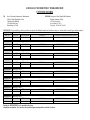
January 30, 2014 ADDENDUM NO. 2 To the BID DOCUMENTS FOR: Renovation of Isaac Delgado Hall Auditorium Delgado Community College New Orleans, Louisiana 19-641-96-03, Part 03 HMS Architects, apc 1515 Poydras St, Suite 2150 New Orleans, Louisiana 70112 Project # 09-043 The following list of revisions and/or enclosures alters and modifies the above referenced plans and specifications previously dated July 25, 2012. The provisions of all of the Contract Documents are hereby made a part of this revision to the plans and specifications. ___________________________________________________________________________________ ENCLOSURES: Item Bid Form Unit Price Form Sheet M101 Sheet M201 Sheet M301 Spec 083313 Spec 230900 Date 1/30/14 1/30/14 1/30/14 1/30/14 1/30/14 1/30/14 1/30/14 Description Revised Bid Form with added Alternate #3 Revised Unit Price form with added Unit Price for Masonry Repair Mechanical First Floor Plan Mechanical Details Mechanical Legend Notes and Schedules Coiling Counter Doors Instrumentation and Controls for HVAC, Alternate #3 • GENERAL: Item 1. Bid form: Replace Bid Form with attached revised Bid Form with added Alternate #3. Item 2. Unit Price form: Replace Unit Price Form with attached revised Unit Price Form with added unit price for Existing Masonry Wall Repair. • DRAWINGS: Item 3. Item 4. Item 5. Sheet M101: a) Replace Sheet M101 with attached revised M101 Sheet M201 a) Replace sheet M201 with attached revised M201 Sheet M301 a) Replace sheet M301 with attached revised M301 • SPECIFICATIONS: Item 6. Section 012200 Unit Prices a) Add the following under part 1.03 Schedule of Unit Prices B. Existing masonry wall repair as per detail 13/S100. Unit price shall be on a single 16” long section either horizontal or vertical. Addendum No. 2 - Page 1 of 4 January 30, 2014 Item 7. Insert Section 083313 Coiling Counter Doors Item 8. Section 096800 a) Part 3.01.B, delete the word “cushion”. b) Delete part 3.02 Stretched-In Carpet, replace with the following: 3.02 Direct Glued Carpet A. Direct Glue-Down Installation: Comply with CRI 104, Section 8: “Direct Glue-Down” B. Comply with carpet manufacturer’s recommendations for seam locations and direction of carpet; maintain uniformity of carpet direction and lay of pile. At doorways, center seams under door in closed position. Do not bridge building expansion joints with continuous carpet. C. Cut and fit carpet to butt tightly to vertical surfaces, permanent fixtures, and built-in furniture including cabinets, pipes, outlets, edgings, thresholds and nosings. Bind or seal cut edges as recommended by carpet manufacturer. D. Extend carpet into toe spaces, door reveals, closets, open-bottomed obstructions, removable flanges, alcoves, and similar openings. c) Add the following parts: 3.4 Cleaning A. Perform the following operations immediately after completion installation. 1. Remove visible adhesive, seam sealer, and other surface blemishes using clear recommended by carpet manufacturer. 2. Remove protruding yarns from carpet surface. 3. Vacuum carpet using commercial machine with face-beater treatment. 3.5 Protection A. Comply with CRI 104, Section 15: “Protection of Indoor Installation.” B. Provide final protection and maintain conditions, in a manner acceptable to manufacturer and installer, that ensure carpet is without damage or deterioration at time of Substantial Completion. Item 9. Section 230900 a) Add Section 230900 Instrumentation and Controls for HVAC, Alternate #3 • PRIOR APPROVALS: Listed below are manufacturers who are recognized as capable of producing materials, manufactured items, and articles of equipment similar to those specified. Products will be considered acceptable providing the equipment meets, or exceeds specification requirements, has the capacity and performance requirements, fits the space available to the satisfaction of the Engineer or Architect, conforms in every respect with the applicable regulatory agencies. Contractor shall submit for approval large scale drawings of proposed layouts and arrangements of substitute equipment when requested. Unless otherwise noted, the listed prior approvals are not given with respect to any specific model, series, catalog number, etc. Suppliers are cautioned that before their equipment is actually approved; it will be incumbent upon them to demonstrate to the Engineer or Architect that it is in fact equal to the requirements specified and conforms fully to all specification requirements. This includes any attachments to this addendum. Item 10. Drawing M301 a) Exhaust/Supply Fan Schedule*: Pennbarry REX33B b) Louver/Damper Schedule*: Pottorff FSD-151, CD-41, EXD-645, EXD-245 *All actuators shall be brushless DC Type, see Controls Item 11. Drawing P101 a) Lav track carrier – Watts DRA TCA-411 b) Wall Hung Lavatory – Gerber 12-654 c) Centerset Single Lever Faucet – Speakman S-3562-LD Item 12. 087100 - Door Hardware a) Hinges – Ives 5BB1, 5BB1HW Addendum No. 2 - Page 2 of 4 January 30, 2014 b) Cylinders – Schlage Everest 29 Item 13. 095100 – Acoustical Ceilings a) Suspension System Type GR-2 – Chicago Metallic 4000 Tempra 9/16” b) Suspension System Types 1 and GR-1 – Chicago Metallic 1200 Seismic 15/16” Item 14. 265100 – Lighting (from Fixture Schedule on E401) a) F1 – Juno TC906-643C-WH-LB27; Lithonia LP6N 6O9AZ; Nora NHIC-17QAT/NTS-31A b) F3 – Horizon S-2-32-D; Lithonia C 2 32 MVOLT GEB10IS; Williams 76-4-232-EB2-UNV c) F4 – Horozon TR2-3-32-SW-D; Lithonia 2GT8 3 32 A12 MVOLT 1/3 GEB10IS; Williams 50G-S24-332-SA12125-EB3-UNV d) F5 – Lumiere Zuma 1212-LA-INC20-120-CS; Lumenton SL630-INC-120 ; Con-Tech STP13-FP-L-B e) F5B – Philips Gardco 962 Square-S-4-UNIV; Fail-Safe Circadian MHN-UNV; Juno LMSW3K-C; C.W. Cole L157G-HO f) F7 – Williams 50G-S24-332-SA12125-EB2/1-UNV g) F9 – Architectural Lighting Works LPRVF-4’-LEDW5-LED0-10V-WH (vertical or horizontal TBD); Axis PRWLED-B2-500-30-S-4-W-UNV-D-1 (orientation as per architectural) h) F10 – Horizon IS-2-59-S-D; Lithonia TL 2 32 MVOLT GEB10IS; Williams 80-8-286-EB2UNV i) F11 – Spectrum Lighting SPC0810-INC-R40-8115-SG-WH-SM; Con-Tech CI6-C-C-B; Williams RC60-75PAR38/MED-BLK-120 j) TRK – Juno T12-BL, T21-BL, T20BL, R712BL ; Con-Tech NTEK44-B/CTL2116-B ; Nora NT302B, NT-311B, NT-309B, NHT-120B k) EX – EXITRONIX VEX-U-PB-WB; NavLite NXPB-3-R ; Isolite RL-EM-R ; LightAlarms GRANNR • BIDDER QUESTIONS: Item 15. Q: Will any contractor parking be provided on site? A: Delgado will allocate some parking for the contractor on the north side of Building 1. Delgado generally provides between 5 and 8 parking passes to general contractors. Delgado suggests that contractor employees park off-site as much as possible by either parking on the street or carpooling. Item 16. Q: Hollow Metal Doors and Frames section part 2.04.A.1.b calls for Level 2 frames, where as all doors listed previously in this section part 2.03 Steel Doors provides for Level 3 doors. Typically we see frames provided at or above the level of the door specified. Please advise. A: Part 2.04.A.1 specifically states “Comply with the requirements of grade specified for corresponding door.” Item 17. Q: Can you provide information for the roofing subcontractor who performed the work on the existing system? A: From the information given to us by the State, the Roofing Guarantee for the work was performed by the Lathan Company, Inc of Mobile, AL. The work was accepted on 5/07/04. Item 18. Q: There is no product substitution request form provided for in the specifications. Please advise. A: HMS Architects will accept product substitution requests without a provided standard form provided detailed information is provided as per the Instructions to Bidders part 4.3.2. Item 19. Q: Can you provide approximate quantities for the existing brick wall crack repair as detailed in 13/S100? A: Brick repair is for anticipated unforeseen conditions. Please see revisions in this addenda to Unit Price specifications, and Unit Price Form. Item 20. Q: Plan sheet S105 indicates 6 locations for an HSS6x6x5/16” hanger, but no details are provided. Please provide length and attachment details for these locations. A: Plan sheet S105 Addendum No. 2 - Page 3 of 4 January 30, 2014 refers to detail 11/S100 Typ. for this location. Sheet S104 shows the bottom of the hangers in question, and refers to details 5 and 6/S300. Item 21. Q: Plan sheet A620, Window Type A is detailed in 3/A620 as an acoustical window system. There is no reference in the division 8 specifications regarding this window type. Please advise. A: Window Types A and B on Window Schedule on A620 are referred to as “STC 39” in the Remarks section. Window Schedule further notes Glazing Type S-3, which is defined in the specifications as “Acoustic Glazing: Laminated Glass”. For window Type A a window shall be provided that meets all of the requirements described in the drawings and specifications, including but not limited to STC-39, operable (OXO per legend and elevation 1/A501) and as detailed on 3/A620. For window Type B a window shall be provided that meets all of the requirements described in the drawings and specifications including but not limited to STC-39, fixed and size shown on Window Types (B) A620. Item 22. Q: The specification says that the fire alarm system is an existing Simplex system. Is that the case? A: Yes, the existing Building 1 fire alarm system is a Simplex system. Item 23. Q: The specifications say that the fire alarm system is “in addition to or connected to this existing system”, please explain to what level of connection is required. A: The intent is for the added components to communicate on a line-level and NOT simply monitored by the existing system using dry contact relay outputs. END OF ADDENDUM NO. 2 Addendum No. 2 - Page 4 of 4 LOUISIANA UNIFORM PUBLIC WORK BID FORM TO: State of Louisiana, Department of Administration Office of Facility Planning & Control Claiborne Office Building 1201 North Third Street Baton Rouge, LA 70804 BID FOR: Renovation of Isaac Delgado Hall Auditorium Delgado Community College 615 City Park Avenue New Orleans, LA 70119 Project No.: 19-641-96-03, Part 03 The undersigned bidder hereby declares and represents that she/he; a) has carefully examined and understands the Bidding Documents, b) has not received, relied on, or based his bid on any verbal instructions contrary to the Bidding Documents or any addenda, c) has personally inspected and is familiar with the project site, and hereby proposes to provide all labor, materials, tools, appliances and facilities as required to perform, in a workmanlike manner, all work and services for the construction and completion of the referenced project, all in strict accordance with the Bidding Documents prepared by: HMS Architects and dated: June 25, 2013. Bidders must acknowledge all addenda. The Bidder acknowledges receipt of the following ADDENDA: (Enter the number the Designer has assigned to each of the addenda that the Bidder is acknowledging) __________________________________________ . TOTAL BASE BID: For all work required by the Bidding Documents (including any and all unit prices designated “Base Bid” * but not alternates) the sum of: Dollars ($ ) ALTERNATES: For any and all work required by the Bidding Documents for Alternates including any and all unit prices designated as alternates in the unit price description. Alternate No. 1 All Acoustical wall panels (AWP-1) in Auditorium and Lobby for the lump sum of: Dollars ($ ) Alternate No. 2 Additional Dead Hung Riggins (see TPR 101) for the lump sum of: Dollars ($ ) Alternate No. 3 Building Automation System as per 230900 Instrumentation & Controls for HVAC for the lump sum of: Dollars ($ ) NAME OF BIDDER: ADDRESS OF BIDDER: LOUISIANA CONTRACTOR’S LICENSE NUMBER: NAME OF AUTHORIZED SIGNATORY OF BIDDER: TITLE OF AUTHORIZED SIGNATORY OF BIDDER: SIGNATURE OF AUTHORIZED SIGNATORY OF BIDDER **: DATE: _______________________ * The Unit Price Form shall be used if the contract includes unit prices. Otherwise it is not required and need not be included with the form. The number of unit prices that may be included is not limited and additional sheets may be included if needed. ** If someone other than a corporate officer signs for the Bidder/Contractor, a copy of a corporate resolution or other signature authorization shall be required for submission of bid. Failure to include a copy of the appropriate signature authorization, if required, may result in the rejection of the bid unless bidder has complied with La. R.S. 38:2212(A)(1)(c) or RS 38:2212(O) . BID SECURITY in the form of a bid bond, certified check or cashier’s check as prescribed by LA RS 38:2218.A is attached to and made a part of this bid. LOUISIANA UNIFORM PUBLIC WORK BID FORM UNIT PRICE FORM TO: State of Louisiana, Department of Administration Office of Facility Planning & Control Claiborne Office Building 1201 North Third Street Baton Rouge, LA 70804 BID FOR: Renovation of Isaac Delgado Hall Auditorium Delgado Community College 615 City Park Avenue New Orleans, LA 70119 Project No.: 19-641-96-03, Part 03 UNIT PRICES: This form shall be used for any and all work required by the Bidding Documents and described as unit prices. Amounts shall be stated in figures and only in figures. DESCRIPTION: REF. NO. Base Bid or Alt.# ___Hazardous Materials Abatement QUANTITY: UNIT OF MEASURE: All N/A UNIT PRICE UNIT PRICE EXTENSION (Quantity times Unit Price) UNIT PRICE EXTENSION (Quantity times Unit Price) 02 Base Bid or Alt.# ___Existing Masonry Wall repair as per detail 13/S100 QUANTITY: UNIT OF MEASURE: UNIT PRICE 1 16” DESCRIPTION: REF. NO. Base Bid or Alt.# ___ QUANTITY: UNIT OF MEASURE: UNIT PRICE UNIT PRICE EXTENSION (Quantity times Unit Price) DESCRIPTION: REF. NO. Base Bid or Alt.# ___ QUANTITY: UNIT OF MEASURE: UNIT PRICE UNIT PRICE EXTENSION (Quantity times Unit Price) DESCRIPTION: REF. NO. Base Bid or Alt.# ___ QUANTITY: UNIT OF MEASURE: UNIT PRICE UNIT PRICE EXTENSION (Quantity times Unit Price) DESCRIPTION: REF. NO. Base Bid or Alt.# ___ QUANTITY: UNIT OF MEASURE: UNIT PRICE UNIT PRICE EXTENSION (Quantity times Unit Price) DESCRIPTION: REF. NO. Base Bid or Alt.# ___ QUANTITY: UNIT OF MEASURE: UNIT PRICE UNIT PRICE EXTENSION (Quantity times Unit Price) DESCRIPTION: REF. NO. Base Bid or Alt.# ___ QUANTITY: UNIT OF MEASURE: UNIT PRICE UNIT PRICE EXTENSION (Quantity times Unit Price) 01 DESCRIPTION: REF. NO. Wording for “DESCRIPTION” is to be provided by the Owner. All quantities are estimated. The contractor will be paid based upon actual quantities as verified by the Owner Renovation to Delgado Hall Auditorium Delgado Community College New Orleans FP&C 19-641-96-03, Part 03 HMS# 09-043-01 January 30, 2014 SECTION 08 33 13 COILING COUNTER DOORS PART 1 GENERAL 1.01 SECTION INCLUDES A. Non-fire-rated coiling counter doors and operating hardware. 1.02 RELATED REQUIREMENTS A. Section 06 10 00 - Rough Carpentry: Openings. B. Section 09 21 16 - Gypsum Board Assemblies: Openings. 1.03 REFERENCE STANDARDS A. ASTM B221 - Standard Specification for Aluminum and Aluminum-Alloy Extruded Bars, Rods, Wire, Profiles, and Tubes; 2013. B. ASTM B221M - Standard Specification for Aluminum and Aluminum-Alloy Extruded Bars, Rods, Wire, Profiles, and Tubes [Metric]; 2013. 1.04 SUBMITTALS A. See Section 01 30 00 - Administrative Requirements, for submittal procedures. B. Product Data: Submit manufacturer's standard literature showing materials and details of construction and finish. Include data on electrical operation. C. Shop Drawings: Indicate rough and actual opening dimensions, anchorage methods, hardware locations, and installation details. D. Samples: Submit two slats, 4 inches long illustrating shape, color and finish texture. E. Manufacturer's Instructions: Indicate installation sequence and installation, adjustment, and alignment procedures. F. Operation and Maintenance Data: Indicate modes of operation, lubrication requirements and frequency, and periodic adjustments required. PART 2 PRODUCTS 2.01 MANUFACTURERS A. Coiling Counter Doors: 1. Cookson; Product Rolling Counter Door. 2. Overhead Door; Product Rolling Counter Door 3. Substitutions: See Section 01 60 00 - Product Requirements. 2.02 COILING COUNTER DOORS A. Coiling Counter Doors, Non-Fire-Rated: Aluminum slat curtain. 1. Mounting: As indicated. 2. Nominal Slat Size: 1-1/4 inches wide. 3. Slat Profile: Flat, perforated. 4. Finish: Anodized. 5. Guides: Formed track; same material and finish unless otherwise indicated. 6. Hood: Manufacturer's standard;, finished to match curtain. 2.03 MATERIALS A. Curtain Construction: Interlocking, single thickness slats. 1. Slat Ends: Alternate slats fitted with end locks to act as wearing surface in guides and to prevent lateral movement. 2. Curtain Bottom: Fitted with angles to provide reinforcement and positive contact in closed position. 3. Aluminum Slats: ASTM B221 (ASTM B221M), aluminum alloy Type 6063; minimum thickness 0.05 inch. COILING COUNTER DOORS 08 33 13- 1 Renovation to Delgado Hall Auditorium Delgado Community College New Orleans FP&C 19-641-96-03, Part 03 HMS# 09-043-01 January 30, 2014 B. Guide Construction: Continuous, of profile to retain door in place, with mounting brackets of same metal. 1. Aluminum Guides: Extruded aluminum channel, with wool pile runners along inside. C. Hood Enclosure: Internally reinforced to maintain rigidity and shape. D. Latching: Inside mounted, sliding deadbolt. E. Roller Shaft Counterbalance: Steel pipe and torsion steel spring system, capable of producing torque sufficient to ensure smooth operation of curtain from any position and capable of holding position at mid-travel; with adjustable spring tension; requiring 25 lb nominal force to operate. PART 3 EXECUTION 3.01 INSTALLATION A. Install units in accordance with manufacturer's instructions. B. Use anchorage devices to securely fasten assembly to wall construction and building framing without distortion or stress. C. Securely and rigidly brace components suspended from structure. Secure guides to structural members only. D. Fit and align assembly including hardware; level and plumb, to provide smooth operation. 3.02 TOLERANCES A. Maintain dimensional tolerances and alignment with adjacent work. B. Maximum Variation From Plumb: 1/16 inch. C. Maximum Variation From Level: 1/16 inch. D. Longitudinal or Diagonal Warp: Plus or minus 1/8 inch per 10 ft straight edge. 3.03 ADJUSTING A. Adjust operating assemblies for smooth and noiseless operation. 3.04 CLEANING A. Clean installed components. B. Remove labels and visible markings. END OF SECTION COILING COUNTER DOORS 08 33 13- 2 Renovation to Delgado Hall Auditorium Delgado Community College New Orleans FP&C #199-641-96-03 Part 03 HMS# 09-043-01 th Alternate # 3-January 30 , 2014 SECTION 23 09 00 - INSTRUMENTATION AND CONTROL FOR HVAC PART 1 GENERAL 1.1 1. 2 SCOPE OF WORK A. The Building Automation System (BAS) manufacturer shall furnish and install a fully integrated building automation system, incorporating direct digital control (DDC) for energy management, equipment monitoring and control, and subsystems with open communications capabilities as herein specified. The system shall be compatible with the existing Siemens Building Technologies Apogee system, currently installed throughout the facility. B. The installation of the control system shall be performed under the direct supervision of the controls manufacturer with the shop drawings, flow diagrams, bill of materials, component designation or identification number and sequence of operation all bearing the name of the manufacturer. The installing manufacturer shall certify in writing, that the shop drawings have been prepared by the equipment manufacturer and that the equipment manufacturer has supervised their installation. In addition, the equipment manufacturer shall certify, in writing, that the shop drawings were prepared by their company and that all temperature control equipment was installed under their direct supervision. C. All materials and equipment used shall be standard components, regularly manufactured for this and/or other systems and not custom designed uniquely for this project. All systems and components shall have been thoroughly tested and proven in actual use for at least two years. D. BAS manufacturer shall be responsible for all BAS and Temperature Control wiring for a complete and operable system. All wiring shall be done in accordance with all local and national codes. WORK BY OTHERS A. Mechanical contractor installs all wells, valves, taps, dampers, flow stations, etc. furnished by BAS manufacturer. It is the responsibility of the control contractor to coordinate his/her work with the electrical & mechanical contractors. Any conflict or components, circuits, devices, wires etc that need to be added to make complete system although not shown on the plans, shall be the full responsibility of the general and control contractors. B. Electrical Contractor provides: 1. 120V power to all BAS and/or Temperature control panels 2. Wiring of all power feeds through all disconnect starters to electrical motor. 3. Wiring of any remote start/stop switches and manual or automatic motor speed control devices not furnished by BAS manufacturer 4. Wiring of any electrical sub-metering devices furnished by BAS manufacturer. C. Products furnished but not installed under this section INSTRUMENTATION AND CONTROL FOR HVAC 230900 - 1 Renovation to Delgado Hall Auditorium Delgado Community College New Orleans FP&C #199-641-96-03 Part 03 HMS# 09-043-01 th Alternate # 3-January 30 , 2014 1. Hydronic Piping: a. Control Valves b. Flow Switches c. Temperature Sensor Wells and Sockets d. Flow Meters D. 1.3 Refrigerant Piping: a. Pressure and Temperature Sensor Wells and Sockets 3. Duct-work Accessories: a. Automatic Dampers b. Air-flow Stations c. Terminal Unit Controls Products installed but not furnished under this section 1. Refrigeration Equipment: a. Pressure Transmitters b. Temperature Transmitters c. Power Transmitters d .Refrigerant Leak Detectors 2. Air Handling Equipment: a. Thermostats b. Sensors c. Controllers 3. Fire Alarm Systems a. Smoke Detectors RELATED WORK A. B. C. 1.4 2. Division 01000 General and Special Conditions Division 23000 Mechanical Division 26000 Electrical QUALITY ASSURANCE A. The BAS system shall be designed, installed, commissioned and serviced by a manufacturer employed and factory trained personnel. Manufacturer shall have an in-place support facility within 100 miles of the site with technical staff, spare parts inventory and necessary test and diagnostic equipment. Distributors or licensed installing contractors are not acceptable. The manufacturer shall provide full time, on site, experienced project manager for this work, responsible for direct supervision of the design, installation, start up and commissioning of the B.M.S. INSTRUMENTATION AND CONTROL FOR HVAC 230900 - 2 Renovation to Delgado Hall Auditorium Delgado Community College New Orleans FP&C #199-641-96-03 Part 03 HMS# 09-043-01 th Alternate # 3-January 30 , 2014 The Bidder shall be regularly engaged in the manufacturing, installation and maintenance of B.M.S. systems and shall have a minimum of ten (10) years of demonstrated technical expertise and experience in the manufacture, installation and maintenance of B.M.S. systems similar in size and complexity to this project. A maintained service organization consisting of at least ten (10) competent servicemen for a period of not less than ten years and provide a list of 10 projects, similar in size and scope to this project, completed within the last five years. B. Materials and equipment shall be the catalogued products of manufacturers regularly engaged in production and installation of automatic temperature control systems and shall be manufacturer's latest standard design that complies with the specification requirements. C. All BAS peer-to-peer network controllers, central system controllers and local user displays shall be UL Listed under Standard UL 916, category PAZX; Standard ULC C100, category UUKL7; and under Standard UL 864, categories UUKL, UDTZ, and QVAX. and be so listed at the time of bid. All floor level controllers shall comply, at a minimum, with UL Standard UL 91 6category PAZX; Standard UL 864, categories UDTZ, and QVAX. and be so listed at the time of Bid. D. The B.A.S. peer-to-peer network controllers and local user display shall also comply with the Australian Electromagnetic Compatibility (EMC) Framework, and bear the C-Tic Mark to show compliance. The purpose of the regulation is to minimize electromagnetic interference between electronic products, which may diminish the performance of electrical products or disrupt essential communications. E. DDC peer-to-peer controllers shall be compliant with the European EMC Directive, Standards EN 50081-2 and EN 50082-2, at the Industrial Levels. Additionally the equipment shall be compliant with the European LVD Directive and bear the CE mark in order to show compliance to both Directives." F. All electronic equipment shall conform to the requirements of FCC Regulation, Part 15, that governs Radio Frequency Electromagnetic Interference and be so labeled. G. The manufacturer of the building automation system shall provide documentation supporting compliance with ISO-9002 (Model for Quality Assurance in Production, Installation, and Servicing) and ISO-140001 (The application of well-accepted business management principles to the environment). The intent of this specification requirement is to ensure that the products from the manufacturer are delivered through a Quality System and Framework that will assure consistency in the products delivered for this project. H. This system shall have a documented history of compatibility by design for a minimum of 15 years. Future compatibility shall be supported for no less than 10 years. Compatibility shall be defined as the ability to upgrade existing field panels to current level of technology, and extend new field panels on a previously installed network. Compatibility shall be defined as the ability for any existing field panel microprocessor to be connected and directly communicate with new field panels without bridges, routers or protocol converters. INSTRUMENTATION AND CONTROL FOR HVAC 230900 - 3 Renovation to Delgado Hall Auditorium Delgado Community College New Orleans 1. 5 FP&C #199-641-96-03 Part 03 HMS# 09-043-01 th Alternate # 3-January 30 , 2014 SUBMITTALS A. Submit 10 complete sets of documentation in the following phased delivery schedule: 1. 2. 3. 4. B. Valve and damper schedules Equipment data cut sheets System schematics, including: ●sequence of operations ●point names ●point addresses ●interface wiring diagrams ●panel layouts. ●system riser diagrams Auto-CAD compatible as-built drawings Upon project completion, submit operation and maintenance manuals, consisting of the following: ●Index sheet, listing contents in alphabetical order ●Manufacturer's equipment parts list of all functional components of the system, Auto-CAD disk of system schematics, including wiring diagrams ●Description of sequence of operations ●As-Built interconnection wiring diagrams ●Operator's Manual ●Trunk cable schematic showing remote electronic panel locations, and all trunk data ●List of connected data points, including panels to which they are connected and input device (ionization detector, sensors, etc.) ●Conduit routing diagrams 1.6 WARRANTY A. Provide all services, materials and equipment necessary for the successful operation of the entire BAS system for a period of one year after beneficial use. B. The adjustment, required testing, and repair of the system includes all computer equipment, transmission equipment and all sensors and control devices. C. The on-line support services shall allow the local BAS subcontractor to dial out over telephone lines to monitor and control the facility's building automation system. This remote connection to the facility shall be within 2 hours of the time that the problem is reported. This coverage shall be extended to include normal business hours, after business hours, weekends and holidays. If the problem cannot be resolved on-line by the local office, the national office of the INSTRUMENTATION AND CONTROL FOR HVAC 230900 - 4 Renovation to Delgado Hall Auditorium Delgado Community College New Orleans FP&C #199-641-96-03 Part 03 HMS# 09-043-01 th Alternate # 3-January 30 , 2014 building automation system manufacturer shall have the same capabilities for remote connection to the facility. If the problem cannot be resolved with on-line support services, the BAS manufacturer shall dispatch the appropriate personnel to the job site to resolve the problem within 3 hours of the time that the problem is reported. PART 2 - PRODUCTS 2.1 ACCEPTABLE MANUFACTURERS A. 2.2 Siemens Building Technologies, Inc. Johnson Controls Honeywell Inc. Carrier Comfort Network Trane McQuay Approved equal with prior approval NETWORKING COMMUNICATIONS A. The design of the BAS shall network operator workstations and stand-alone DDC Controllers. The network architecture shall consist of multiple levels for communication efficiency, a campus-wide (Management Level Network) Ethernet network based on TCP/IP protocol, high performance peer-to-peer building level network(s) and DDC Controller floor level local area networks with access being totally transparent to the user when accessing data or developing control programs. B. The design of BAS shall allow the co-existence of new DDC Controllers with existing DDC Controllers in the same network without the use of gateways or protocol converters. 1. System shall have the capability to communicate with a BACnet network over Ethernet or BACnet/IP (according to Annex J). The intent is to use the system provided under this contract to communicate with control systems provided by other vendors. A PICS must be provided describing the BACnet, ANSI/ASHRAE 135-95, implementation. Minimum system functionality must include monitoring, commanding, and alarming for daily operator functions from a common workstation. 2. System shall have the capability to be an OPC Client and Server for dynamic communication with OPC Clients or Servers over an Ethernet network. At a minimum, the following must be supported: a. Data Access 1.0 (96), 1.0A (97) and 2.0 (11/98) b. Alarms & Events 1.0 (1/99) INSTRUMENTATION AND CONTROL FOR HVAC 230900 - 5 Renovation to Delgado Hall Auditorium Delgado Community College New Orleans E. FP&C #199-641-96-03 Part 03 HMS# 09-043-01 th Alternate # 3-January 30 , 2014 Peer-to-Peer Building Level Network: 1. All operator devices either network resident or connected via dial-up modems shall have the ability to access all point status and application report data or execute control functions for any and all other devices via the peer-to-peer network. No hardware or software limits shall be imposed on the number of devices with global access to the network data at any time. 2. The peer-to-peer network shall support a minimum of 100 DDC controllers and PC workstations 3. Each PC workstation shall support a minimum of 4 peer to peer networks hardwired or dial up. 4. The system shall support integration of third party systems (fire alarm, security, lighting, PCL, chiller, boiler) via panel mounted open protocol processor. This processor shall exchange data between the two systems for interprocess control. All exchange points shall have full system functionality as specified herein for hardwired points. 5. Field panels must be capable of integration with open standards including Modbus, BACnet, and Lonworks as well as with third party devices via existing vendor protocols. 2.3 DDC CONTROLLER FLOOR LEVEL NETWORK: A. This level communication shall support a family of application specific controllers and shall communicate with the peer-to-peer network through DDC Controllers for transmission of global data. 2.4 2.4.1 DDC & HVAC MECHANICAL EQUIPMENT CONTROLLERS A. The DDC & HVAC Mechanical Equipment Controllers shall reside on the Building Network. Level B. DDC & HVAC Mechanical Equipment Controllers shall use the same programming language and tools. DDC & HVAC Mechanical Equipment Controllers which require different programming language or tools on a network are not acceptable. C. DDC & HVAC Mechanical Equipment Controllers which do not meet the functions specified in Section 2.4.1 and Section 2.5 for DDC Controllers or Section 2.4.2 and Section 2.5 for HVAC Mechanical Equipment Controllers are not acceptable. DDC CONTROLLER A. DDC Controllers shall be a 16-bit stand-alone, multi-tasking, multi-user, real-time digital control processors consisting of modular hardware with plug-in enclosed processors, INSTRUMENTATION AND CONTROL FOR HVAC 230900 - 6 Renovation to Delgado Hall Auditorium Delgado Community College New Orleans FP&C #199-641-96-03 Part 03 HMS# 09-043-01 th Alternate # 3-January 30 , 2014 communication controllers, power supplies and input/output point modules. Controller size shall be sufficient to fully meet the requirements of this specification and the attached point I/O schedule. Each controller shall support a minimum of three (3) Floor Level Application Specific Controller Device Networks. B. Each DDC Controller shall have sufficient memory to support its own operating system and databases, including: 1. 2. 3. 4. 5. 6. 7. 8. 9. Control processes Energy management applications Alarm management applications including custom alarm messages for each level alarm for each point in the system. Historical/trend data for points specified Maintenance support applications Custom processes Operator I/O Dial-up communications Manual override monitoring C. Each DDC Controller shall support firmware upgrades without the need to replace hardware. D. Provide all processors, power supplies and communication controllers so that the implementation of a point only requires the addition of the appropriate point input/output termination module and wiring. E. DDC Controllers shall provide a RS-232C serial data communication ports for operation of operator I/O devices such as industry standard printers, operator terminals, modems and portable laptop operator's terminals. DDC Controllers shall allow temporary use of portable devices without interrupting the normal operation of permanently connected modems, printers or terminals. F. As indicated in the point I/O schedule, the operator shall have the ability to manually override automatic or centrally executed commands at the DDC Controller via local, point discrete, on-board hand/off/auto operator override switches for digital control type points and gradual switches for analog control type points. G. 1. Switches shall be mounted either within the DDC Controllers key-accessed enclosure, or externally mounted with each switch keyed to prevent unauthorized overrides. 2. DDC Controllers shall monitor the status of all overrides and inform the operator that automatic control has been inhibited. DDC Controllers shall also collect override activity information for reports. DDC Controllers shall provide local LED status indication for each digital input and output for constant, up-to-date verification of all point conditions without the need for an operator I/O device. Graduated intensity LEDs or analog indication of value shall also be provided for each analog output. Status indication shall be visible without opening the panel door. INSTRUMENTATION AND CONTROL FOR HVAC 230900 - 7 Renovation to Delgado Hall Auditorium Delgado Community College New Orleans H. I. J. K. 2.4.2 FP&C #199-641-96-03 Part 03 HMS# 09-043-01 th Alternate # 3-January 30 , 2014 Each DDC Controller shall continuously perform self-diagnostics, communication diagnosis and diagnosis of all panel components. The DDC Controller shall provide both local and remote annunciation of any detected component failures, low battery conditions or repeated failure to establish communication. Isolation shall be provided at all peer-to-peer network terminations, as well as all point terminations to suppress induced voltage transients consistent with: field 1. RF-Conducted Immunity (RFCI) per ENV 50141 (IEC 1000-4-6) at 3 V 2. Electro Static Discharge (ESD) Immunity per EN 61000-4-2 (IEC 1000-4-2) at 8 kV air discharge, 4 kV contact 3. Electrical Fast Transient (EFT) per EN 61000-4-4 (IEC 1000-4-4) at 500 V signal, 1 kV power 4. Output Circuit Transients per UL 864 (2,400V, 10A, 1.2 Joule max) 5. Isolation shall be provided at all peer-to-peer panel's AC input terminals to suppress induced voltage transients consistent with: a. IEEE Standard 587-1980 b. UL 864 Supply Line Transients c. Voltage Sags, Surge, and Dropout per EN 61000-4-11 (EN 1000-4-11) In the event of the loss of normal power, there shall be an orderly shutdown of all DDC Controllers to prevent the loss of database or operating system software. Non-volatile memory shall be incorporated for all critical controller configuration data and battery backup shall be provided to support the real-time clock and all volatile memory for a minimum of 60 days. 1. Upon restoration of normal power, the DDC Controller shall automatically resume full operation without manual intervention. 2. Should DDC Controller memory be lost for any reason, the user shall have the capability of reloading the DDC Controller via the local RS-232C port, via telephone line dial-in or from a network workstation PC. Provide a separate DDC Controller for each AHU or other HVAC system as indicated in Section 3.02. It is intended that each unique system be provided with its own point resident DDC Controller. HVAC MECHANICAL EQUIPMENT CONTROLLERS INSTRUMENTATION AND CONTROL FOR HVAC 230900 - 8 Renovation to Delgado Hall Auditorium Delgado Community College New Orleans FP&C #199-641-96-03 Part 03 HMS# 09-043-01 th Alternate # 3-January 30 , 2014 A. HVAC Mechanical Equipment Controllers shall be a 12-bit stand-alone, multi-tasking, multi-user, real-time digital control processors consisting of modular hardware with plug-in enclosed processors. B. Each HVAC Mechanical Controller shall have sufficient memory to support its own operating system and databases, including: 1. 2. 3. 4. 5. 6. 7. 8. Control processes Energy management applications Alarm management applications including custom alarm messages for each level alarm for each point in the system. Historical/trend data for points specified Maintenance support applications Custom processes Operator I/O Remote communications C. HVAC Mechanical Equipment Controllers shall provide a RS-232C serial data communication port for operation of operator I/O devices such as industry standard printers, operator terminals, modems and portable laptop operator's terminals. D. HVAC Mechanical Equipment Controllers shall provide local LED status indication for each digital input and output for constant, up-to-date verification of all point conditions without the need for an operator I/O device. E. Each HVAC Mechanical Equipment Controller shall continuously perform self-diagnostics, communication diagnosis and diagnosis of all components. The HVAC Mechanical Equipment Controller shall provide both local and remote annunciation of any detected component failures, low battery conditions or repeated failure to establish communication. F. Isolation shall be provided at all peer-to-peer network terminations, as well as all field point terminations to suppress induced voltage transients consistent with: • RF-Conducted Immunity (RFCI) per ENV 50141 (IEC 1000-4-6) at 3 V • Electro Static Discharge (ESD) Immunity per EN 61000-4-2 (IEC 1000-4-2) at 8 kV air discharge, 4 kV contact • Electrical Fast Transient (EFT) per EN 61000-4-4 (IEC 1000-4-4) at 500 V signal, 1 kV power • Output Circuit Transients per UL 864 (2,400V, 10A, 1.2 Joule max) Isolation shall be provided at all peer-to-peer panel's AC input terminals to suppress induced voltage transients consistent with: • IEEE Standard 587-1980 • UL 864 Supply Line Transients • Voltage Sags, Surge, and Dropout per EN 61000-4-11 (EN 1000-4-11) G. In the event of the loss of normal power, there shall be an orderly shutdown of all HVAC Mechanical Equipment Controllers to prevent the loss of database or operating system software. Non-volatile memory shall be incorporated for all critical controller configuration data and battery backup shall be provided to support the real-time clock and all volatile INSTRUMENTATION AND CONTROL FOR HVAC 230900 - 9 Renovation to Delgado Hall Auditorium Delgado Community College New Orleans FP&C #199-641-96-03 Part 03 HMS# 09-043-01 th Alternate # 3-January 30 , 2014 memory for a minimum of 72 hours. 2.5 1. Upon restoration of normal power, the HVAC Mechanical Equipment Controller shall automatically resume full operation without manual intervention. 2. Should HVAC Mechanical Equipment Controller memory be lost for any reason, the user shall have the capability of reloading the HVAC Mechanical Equipment Controller via the local RS-232C port, via telephone line dial-in or from a network workstation PC. DDC & HVAC MECHANICAL EQUIPMENT CONTROLLER RESIDENT SOFTWARE FEATURES A. B. General: 1. The software programs specified in this Section shall be provided as an integral part of DDC and HVAC Mechanical Equipment Controllers and shall not be dependent upon any higher level computer for execution. 2. All points shall be identified by up to 30 character point name and 16 character point descriptor. The same names shall be used at the PC workstation. 3. All digital points shall have user defined two-state status indication (descriptors with minimum of 8 characters allowed per state (i.e. summer/winter)). Control Software Description: 1. C. The DDC and HVAC Mechanical Equipment Controllers shall have the ability to perform the following pre-tested control algorithms: a. Two-position control b. Proportional control c. Proportional plus integral control d. Proportional, integral, plus derivative control e. Automatic tuning of control loops DDC and HVAC Mechanical Equipment Controllers shall provide the following energy management routines for the purpose of optimizing energy consumption while maintaining occupant comfort. INSTRUMENTATION AND CONTROL FOR HVAC 230900 - 10 Renovation to Delgado Hall Auditorium Delgado Community College New Orleans 1. Start-Stop Time Optimization (SSTO) shall automatically be coordinated with event scheduling. The SSTO program shall start HVAC equipment at the latest possible time that will allow the equipment to achieve the desired zone condition by time of occupancy. The SSTO program shall also shut down HVAC equipment at the earliest possible time before the end of the occupancy period, and still maintain desired comfort conditions. a) The SSTO program shall operate in both the heating and cooling seasons. 1) 2) b) 2. FP&C #199-641-96-03 Part 03 HMS# 09-043-01 th Alternate # 3-January 30 , 2014 It shall be possible to apply the SSTO program to individual fan systems. The SSTO program shall operate on both outside weather conditions as well as inside zone conditions and empirical factors. The SSTO program shall meet the local code requirements for minimum outside air while the building is occupied. Event Scheduling: Provide a comprehensive menu driven program to automatically start and stop designated points or groups of points according to a stored time. a) It shall be possible to individually command a point or group of points. b) For points assigned to one common load group, it shall be possible to assign variable time delays between each successive start or stop within that group. c) The operator shall be able to define the following information: 1. 2. 3. 4. d) Time, day Commands such as on, off, auto, and so forth. Time delays between successive commands. There shall be provisions for manual overriding of each schedule by an appropriate operator. It shall be possible to schedule events up to one year in advance. 1. 2. Scheduling shall be calendar based. Holidays shall allow for different schedules. 3. Enthalpy switchover (economizer) .The Energy Management Control Software (EMCS) will control the position of the air handler relief, return, and outside air dampers. If the outside air dry bulb temperature falls below changeover set point the EMCS will modulate the dampers to provide 100 percent outside air. The user will be able to quickly changeover to an economizer system based on dry bulb temperature and will be able to override the economizer cycle and return to minimum outside air operation at any time. 4. Temperature-compensated duty cycling. INSTRUMENTATION AND CONTROL FOR HVAC 230900 - 11 Renovation to Delgado Hall Auditorium Delgado Community College New Orleans D. FP&C #199-641-96-03 Part 03 HMS# 09-043-01 th Alternate # 3-January 30 , 2014 a) The DCCP (Duty Cycle Control Program) shall periodically stop and start loads according to various patterns. b) The loads shall be cycled such that there is a net reduction in both the electrical demands and the energy consumed. 5. Automatic Daylight Savings Time Switchover: The system shall provide automatic time adjustment for switching to/from Daylight Savings Time. 6. Night setback control: The system shall provide the ability to automatically adjust setpoints for night control. 7. The Peak Demand Limiting (PDL) program shall limit the consumption of electricity to prevent electrical peak demand charges. a) PDL shall continuously track the amount of electricity being consumed, by monitoring one or more electrical kilowatt-hour/demand meters. These meters may measure the electrical consumption (kWh), electrical demand (kW), or both. b) PDL shall sample the meter data to continuously forecast the demand likely to be used during successive time intervals. c) If the PDL forecasted demand indicates that electricity usage is likely to exceed a user preset maximum allowable level, then PDL shall automatically shed electrical loads. d) Once the demand peak has passed, loads that have been shed shall be restored and returned to normal control. DDC and HVAC Mechanical Equipment Controllers shall be able to execute custom, job-specific processes defined by the user, to automatically perform calculations and special control routines. 1. A single process shall be able to incorporate measured or calculated data from any and all other DDC and HVAC Mechanical Equipment Controllers on the network. In addition, a single process shall be able to issue commands to points in any and all other DDC and HVAC Mechanical Equipment Controllers on the network. Database shall support 30 character, English language point names, structured for searching and logs. 2. Processes shall be able to generate operator messages and advisories to operator I/O devices. A process shall be able to directly send a message to a specified device or cause the execution of a dial-up connection to a remote device such as a printer or pager. INSTRUMENTATION AND CONTROL FOR HVAC 230900 - 12 Renovation to Delgado Hall Auditorium Delgado Community College New Orleans E. F. FP&C #199-641-96-03 Part 03 HMS# 09-043-01 th Alternate # 3-January 30 , 2014 3. DDC and HVAC Mechanical Equipment Controller shall provide a HELP function key, providing enhanced context sensitive on-line help with task orientated information from the user manual. 4. DDC and HVAC Mechanical Equipment Controller shall be capable of comment lines for sequence of operation explanation. Alarm management shall be provided to monitor and direct alarm information to operator devices. Each DDC and HVAC Mechanical Equipment Controller shall perform distributed, independent alarm analysis and filtering to minimize operator interruptions due to non-critical alarms, minimize network traffic and prevent alarms from being lost. At no time shall the DDC and HVAC Mechanical Equipment Controllers ability to report alarms be affected by either operator or activity at a PC workstation, local I/O device or communications with other panels on the network. 1. All alarm or point change reports shall include the point's English language description and the time and date of occurrence. 2. The user shall be able to define the specific system reaction for each point. Alarms shall be prioritized to minimize nuisance reporting and to speed operator response to critical alarms. A minimum of six priority levels shall be provided for each point. Point priority levels shall be combined with user definable destination categories (PC, printer, DDC Controller, etc.) to provide full flexibility in defining the handling of system alarms. Each DDC and HVAC Mechanical Equipment Controller shall automatically inhibit the reporting of selected alarms during system shutdown and start-up. Users shall have the ability to manually inhibit alarm reporting for each point. 3. Alarm reports and messages will be directed to a user-defined list of operator devices or PCs based on time (after hours destinations) or based on priority. 4. In addition to the point's descriptor and the time and date, the user shall be able to print, display or store a 200 character alarm message to more fully describe the alarm condition or direct operator response. 5. In dial-up applications, operator-selected alarms shall initiate a call to a remote operator device. A variety of historical data collection utilities shall be provided to manually or automatically sample, store and display system data for points as specified in the I/O summary. 1. Any point, physical or calculated may be designated for trending. Any point, regardless of physical location in the network, may be collected and stored in each DDC and HVAC Mechanical Equipment Controllers point group. Two methods of collection shall be allowed: either by a pre-defined time interval or upon a pre-defined change of value. Sample intervals of l minute to 7 days shall be INSTRUMENTATION AND CONTROL FOR HVAC 230900 - 13 Renovation to Delgado Hall Auditorium Delgado Community College New Orleans FP&C #199-641-96-03 Part 03 HMS# 09-043-01 th Alternate # 3-January 30 , 2014 provided. Each DDC and HVAC Mechanical Equipment Controller shall have a dedicated RAM-based buffer for trend data. All trend data shall be available for transfer to a Workstation without manual intervention. 2. DDC and HVAC Mechanical Equipment Controllers shall also provide high resolution sampling capability for verification of control loop performance. Operator-initiated automatic and manual loop tuning algorithms shall be provided for operator-selected PID control loops as identified in the point I/O summary. a. 2.6 Loop tuning shall be capable of being initiated either locally at the DDC and HVAC Mechanical Equipment Controller, from a network workstation or remotely using dial-in modems. For all loop tuning functions, access shall be limited to authorized personnel through password protection. G. DDC and HVAC Mechanical Equipment Controllers shall be capable of automatically accumulating and storing run-time hours for digital input and output points and automatically sample, calculate and store consumption totals for analog and digital pulse input type points, as specified in the point I/O schedule. H. The peer to peer network shall allow the DDC and HVAC Mechanical Equipment Controllers to access any data from or send control commands and alarm reports directly to any other DDC and HVAC Mechanical Equipment Controller or combination of controllers on the network without dependence upon a central or intermediate processing device. DDC and HVAC Mechanical Equipment Controllers shall send alarm reports to multiple workstation without dependence upon a central or intermediate processing device. The peer to peer network shall also allow any DDC and HVAC Mechanical Equipment Controller to access, edit, modify, add, delete, back up, and restore all system point database and all programs. I. The peer to peer network shall allow the DDC and HVAC Mechanical Equipment Controllers to assign a minimum of 50 passwords access and control priorities to each point individually. The logon password (at any PC workstation or portable operator terminal) shall enable the operator to monitor, adjust and control the points that the operator is authorized for. All other points shall not be displayed on the PC workstation or portable terminal (e.g. all base building and all tenant points shall be accessible to any base building operators, but only tenant points shall be accessible to tenant building operators). Passwords and priorities for every point shall be fully programmable and adjustable. FLOOR LEVEL NETWORK APPLICATION SPECIFIC CONTROLLERS (ASC) A. Each DDC Controller shall be able to extend its performance and capacity through the use of remote application specific controllers (ASCs) through Floor Level LAN Device Networks. B. Each ASC shall operate as a stand-alone controller capable of performing its specified control responsibilities independently of other controllers in the network. Each ASC shall be a microprocessor-based, multi-tasking, real-time digital control processor. Each ASC shall be capable of control of the terminal device independent of the manufacturer of the terminal INSTRUMENTATION AND CONTROL FOR HVAC 230900 - 14 Renovation to Delgado Hall Auditorium Delgado Community College New Orleans FP&C #199-641-96-03 Part 03 HMS# 09-043-01 th Alternate # 3-January 30 , 2014 device. C. Terminal Equipment Controllers: 1. Provide for control of each piece of equipment, including, but not limited to, the following: a. Rooftop Units b. Split System Air Handlers c. Condensing Units d. Exhaust and Supply Fans 2. Controllers shall include all point inputs and outputs necessary to perform the specified control sequences. Analog outputs shall be industry standard signals such as 24V floating control, 0-10v, allowing for interface to a variety of modulating actuators. 3. All controller sequences and operation shall provide closed loop control of the intended application. Closing control loops over the FLN, BLN or MLN is not acceptable 2.11 FIELD DEVICES A. Provide instrumentation as required for monitoring, control or optimization functions. All devices and equipment shall be approved for installation in the City of Chalmette, Louisiana. B. Room Temperature Sensors 1) Digital room sensors shall have LCD display, day / night override button, and setpoint slide adjustment override options. The setpoint slide adjustment can be software limited by the automation system to limit the amount of room adjustment. Temperature monitoring range Output signal Accuracy at Calibration point Set Point and Display Range +20/120°F -13° to 49°C) Changing resistance +0.5°F (+/- 0.3°C) 55° to 95° F (13° to 35°C) 2) Liquid immersion temperature: Temperature monitoring range Output signal Accuracy at Calibration point +30/250°F (-1°/121°C) Changing resistance +0.5°F (+/-0.3°C) 3) Duct (single point) temperature: Temperature monitoring range Output signal Accuracy at Calibration point +20/120°F (-7°/49°C) Changing resistance +0.5°F (+/-0.3°C) INSTRUMENTATION AND CONTROL FOR HVAC 230900 - 15 Renovation to Delgado Hall Auditorium Delgado Community College New Orleans C. FP&C #199-641-96-03 Part 03 HMS# 09-043-01 th Alternate # 3-January 30 , 2014 4) Duct Average temperature: Temperature monitoring range Output signal Accuracy at Calibration point Sensor Probe Length +20° +120°F(-7°/+49°C) 4 – 20 mA DC +0.5°F (+03°C) 25’ L (7.3m) 5) Outside air temperature: Temperature monitoring range Output signal Accuracy at Calibration point -58°+122° F(-50ºC to +50ºC) 4 – 20 mA DC +0.5°F (+/-0.3°C) Liquid Differential Pressure Transmitter Ranges 0-5/30 inches H20 0-25/150 inches H20 0-125/750 inches H20 Output Calibration Adjustments Accuracy Linearity Hysteresis 4 – 20 mA DC Zero and span +-0.2% of span +-0.1% of span +-0.05% of span D. Differential pressure: 1. Unit for fluid flow proof shall be Penn P74. Range Differential Maximum differential pressure Maximum pressure 2. Air Flow Measurement. Set point ranges: 8 to 70 psi 3 psi 200 psi 325 psi 0.5” WG to 1.0” WG (124.4 to 248.8 Pa) 1.0” WG to 12.0” WG (248.8 to 497.6 Pa) E. Static pressure sensor: Range Output Signal Combined static error Operating Temperature F. Air Pressure Sensor: Range: INSTRUMENTATION AND CONTROL FOR HVAC 0 to .5” WG (0 to 124.4 Pa) 0 to 1” WG (0 to 248.8 Pa) 0 to 2” WG (0 to 497.7 Pa) 0 to 5” WG (0 to 1.2 kPa 0 to 10” WG (0 to 2.5 kPa) 4 – 20 mA VDC 0.5% full range -40º to 175º F (-40C to 79.5ºC 0 to 0.1 in. water (0 to 24.9 Pa) 0 to 0.25 in. water (0 to 63.2 Pa) 230900 - 16 Renovation to Delgado Hall Auditorium Delgado Community College New Orleans FP&C #199-641-96-03 Part 03 HMS# 09-043-01 th Alternate # 3-January 30 , 2014 0 to 0.5 in. water (0 to 124.5 Pa) 0 to 1.0 in. water (o to 249 Pa) 0 to 2.0 in water 90 to 498 Pa) 0 to 5.0 in. water (0 to 1.25 kPa) 0 to 10.0 in.water (0 to 2.49 kPa) Output signal Accuracy 4 to 20 mA +1.0% of full scale G. Humidity Sensors: Range Sensing Element Output Signal Accuracy 0 to 100% RH Bulk Polymer 4 – 20 mA DC At 77°F(25ºC) + 2% RH H. Insertion Flow Meters (Equal to Onicon Series F-1200) Sensing Method Accuracy Maximum Operating Pressure Output Signal Impedance Sensing + 2% of Actual Reading 400 PSI 4 – 20 mA Bi-directional where required. I. Pressure to Current Transducer Range Output signal Accuracy 3 to 15 psig (21 to 103 kPa) or 3 to 30 psig (21 to 207 kPa) 4 – 20 mA + 1% of full scale (+ 0.3 psig) J. Control Valves (all control valves shall have electric actuators). 1. Electric Control Rangeability Flow Characteristics Control Action Medium Body Type Body Material Body Trim Stem Actuator 40:1 Modified. Equal percentage Normal open or closed as selected Steam, water, glycol Screwed ends 2” and smaller, flanged Valves 2½” and larger INSTRUMENTATION AND CONTROL FOR HVAC Bronze Bronze Stainless Steel 0-10 VDC, 4-20 MA or 2 position 24 VAC/120VAC 230900 - 17 Renovation to Delgado Hall Auditorium Delgado Community College New Orleans FP&C #199-641-96-03 Part 03 HMS# 09-043-01 th Alternate # 3-January 30 , 2014 2. All automatic temperature control valves in water lines shall be provided with Characterized throttling plugs and shall be sized for minimum 25% of the system pressure drop or 5 psi, whichever is less. a) Positive positioning relays shall be provided on pneumatic control when required to provide sufficient power for sequencing. b) Two position valves shall be line size. K. Damper Actuators 1. Electric control shall be direct coupled actuators. 2. Damper actuators shall be Brushless DC Motor Technology with stall protection, bidirectional, fail safe spring return, all metal housing, manual override, independently adjustable dual auxiliary switch. a)The actuator assembly shall include the necessary hardware and proper mounting and connection to a standard ½” diameter shaft or damper blade. 3. Actuators shall be designed for mounting directly to the damper shaft without the need for connecting linkages. 4. All actuators having more than 100 lb-in torque output shall have a self-centering damper shaft clamp that guarantees concentric alignment of the actuator’s output coupling with the damper shaft. The self-centering clamp shall have a pair of opposed “v” shaped toothed cradles; each having two rows of teeth to maximize holding strength. A single clamping bolt shall simultaneously drive both cradles into contact with the damper shaft. 5. All actuators having more than a 100 lb-in torque output shall accept a 1” diameter shaft directly, without the need for auxiliary adapters. 6. All actuators shall be designed and manufactured using ISO900 registered procedures, and shall be Listed under Standards UL873 and CSA22.2 No. 24-93 l. 2.12 MISCELLANEOUS DEVICES A. Thermostats 1. Room thermostats shall be of the gradual acting type with adjustable sensitivity. 2. They shall have a bi-metal sensing element capable of responding to a temperature change of one-tenth of one degree. (Provide all thermostats with limit stops to limit adjustments as required.) 3. Thermostats shall be arranged for either horizontal or vertical mounting. 4. In the vertical position thermostat shall fit on a mullion of movable partitions without overlap. 5. Mount the thermostat covers with tamper-proof socket head screws. B. Freezestats: INSTRUMENTATION AND CONTROL FOR HVAC 230900 - 18 Renovation to Delgado Hall Auditorium Delgado Community College New Orleans 1. Install freezestats as indicated on the plans and provide protection for every square foot of coil surface area with one linear foot of element per square foot of coil. a) C. Firestats: 1. Upon detection of low temperature, the freezestats shall stop the associated supply fans and return the automatic dampers to their normal position. Provide manual reset. Provide manual reset, fixed temperature line voltage type with a bi-metal actuated switch. a) D. FP&C #199-641-96-03 Part 03 HMS# 09-043-01 th Alternate # 3-January 30 , 2014 Switch shall have adequate rating for required load. Current Sensing Relay: 1. 2. 3. Provide solid-state, adjustable, current operated relay. Provide a relay which changes switch contact state in response to an adjustable set point value of current in the monitored A/C circuit. Adjust the relay switch point so that the relay responds to motor operation under load as an “on” state and so that the relay responds to an unloaded running motor as an “off” state. A motor with a broken belt is considered an unloaded motor. Provide for status device for all fans and pumps. PART 3 - EXECUTION 3.1 PROJECT MANAGEMENT Provide a designated project manager who will be responsible for the following: Construct and maintain project schedule On-site coordination with all applicable trades, subcontractors, and other integration vendors Authorized to accept and execute orders or instructions from owner/architect Attend project meetings as necessary to avoid conflicts and delays Make necessary field decisions relating to this scope of work Coordination/Single point of contact 3.2 SEQUENCE OF OPERATION 3.4 START-UP AND COMMISSIONING A. When installation of the system is complete, calibrate equipment and verify transmission media operation before the system is placed on-line. All testing, calibrating, adjusting and final field tests shall be completed by the manufacturer. Verify that all systems are operable from local controls in the specified failure mode upon panel failure or loss of power. INSTRUMENTATION AND CONTROL FOR HVAC 230900 - 19 Renovation to Delgado Hall Auditorium Delgado Community College New Orleans 3.5 FP&C #199-641-96-03 Part 03 HMS# 09-043-01 th Alternate # 3-January 30 , 2014 B. Provide any recommendation for system modification in writing to owner. Do not make any system modification, including operating parameters and control settings, without prior approval of owner. C. After manufacturer has completed system start-up and commissioning. Joint commissioning of integrated system segments shall be completed. ELECTRICAL WIRING AND MATERIALS Install, connect and wire the items included under this Section. This work includes providing required conduit, wire, fittings, and related wiring accessories. A. Provide wiring between thermostats, aquastats and unit heater motors, all control and alarm wiring for all control and alarm devices for all Sections of Specifications. B. Provide status function conduit and wiring for equipment covered under this Section. C. Provide conduit and wiring between the B.M.S. panels and the temperature, humidity, or pressure sensing elements, including low voltage control wiring in conduit. D. Provide conduit and control wiring for devices specified in this Section. E. Provide conduit and signal wiring between motor starters in motor control centers and high and/or low temperature relay contacts and remote relays in B.M.S. panels located in the vicinity of motor control centers. F. Provide conduit and wiring between the PC workstation, electrical panels, metering instrumentation, indicating devices, miscellaneous alarm points, remotely operated contractors, and B.M.S. panels, as shown on the drawings or as specified. G. All wiring to be compliant to local building code and the NEC. H. Provide electrical wall box and conduit sleeve for all wall mounted devices. 3.7 PERFORMANCE A. 3.8 Unless stated otherwise, control temperatures within plus or minus 2oF humidity within plus or minus 3% of the set point and static pressure within 10% of set point. COMMISSIONING, TESTING AND ACCEPTANCE A. Perform a three-phase commissioning procedure consisting of field I/O calibration and commissioning, system commissioning and integrated system program commissioning. Document all commissioning information on commissioning data sheets which shall be submitted prior to acceptance testing. Commissioning work which requires shutdown of system or deviation from normal function shall be performed when the operation of the system is not required. The commissioning must be coordinated with the owner and construction manager to ensure systems are available when needed. Notify the operating personal in writing of the testing schedule so that authorized personnel from the owner and construction manager are present throughout the INSTRUMENTATION AND CONTROL FOR HVAC 230900 - 20 Renovation to Delgado Hall Auditorium Delgado Community College New Orleans FP&C #199-641-96-03 Part 03 HMS# 09-043-01 th Alternate # 3-January 30 , 2014 commissioning procedure. 1. Prior to system program commissioning, verify that each control panel has been installed according to plans, specifications and approved shop drawings. Test, calibrate and bring on line each control sensor and device. Commissioning to include, but not be limited to: a. Sensor accuracy at 10, 50 and 90% of range. b. Sensor range. c. Verify analog limit and binary alarm reporting. d. Point value reporting. e. Binary alarm and switch settings. f. Actuator ranges. g. Fail safe operation on loss of control signal, electric power, network communications. B. After control devices have been commissioned (i.e. calibrated, tested and signed off), each BMS program shall be put on line and commissioned. The contractor shall, in the presence of the owner and construction manager, demonstrate each programmed sequence of operation and compare the results in writing. In addition, each control loop shall be tested to verify proper response and stable control, within specified accuracy's. System program test results shall be recorded on commissioning data sheets and submitted for record. Any discrepancies between the specification and the actual performance will be immediately rectified and retested. C. After all BMS programs have been commissioned, the contractor shall verify the overall system performance as specified. Tests shall include, but not be limited to: 1. 2. Data communication, both normal and failure modes. Fully loaded system response time. 3. Impact of component failures on system performance and system operation. 4. Time/Date changes. 5. End of month/ end of year operation. 6. Season changeover. 7. Global application programs and point sharing. 8. System backup and reloading. 9. System status displays. INSTRUMENTATION AND CONTROL FOR HVAC 230900 - 21 Renovation to Delgado Hall Auditorium Delgado Community College New Orleans FP&C #199-641-96-03 Part 03 HMS# 09-043-01 th Alternate # 3-January 30 , 2014 10. Diagnostic functions. 11. Power failure routines. 12. Battery backup. 13. Smoke Control, stair pressurization, stair, vents, in concert with Fire Alarm System testing. 14. Testing of all electrical and HVAC systems with other division of work. D. Submit for approval, a detailed acceptance test procedure designed to demonstrate compliance with contractual requirements. This Acceptance test procedure will take place after the commissioning procedure but before final acceptance, to verify that sensors and control devices maintain specified accuracy's and the system performance does not degrade over time. E. Using the commissioning test data sheets, the contractor shall demonstrate each point. The contractor shall also demonstrate all system functions. The contractor shall demonstrate all points and system functions until all devices and functions meet specification. F. The contractor shall supply all instruments for testing and turn over same to the owner after acceptance testing. 1. All test instruments shall be submitted for approval. Test Instrument Accuracy: G. 3.10 Temperature: 1/4F or 1/2% full scale, whichever is less. Pressure: High Pressure (psi): ½ psi or 1/2% full scale, whichever is less. Low Pressure: (in w.c.) 1/2% of full scale Humidity: 2% RH Electrical: 1/4% full scale After the above tests are complete and the system is demonstrated to be functioning as specified, a thirty day performance test period shall begin. If the system performs as specified throughout the test period, requiring only routine maintenance, the system shall be accepted. If the system fails during the test, and cannot be fully corrected within eight hours, the owner may request that performance tests be repeated. TRAINING INSTRUMENTATION AND CONTROL FOR HVAC 230900 - 22 Renovation to Delgado Hall Auditorium Delgado Community College New Orleans FP&C #199-641-96-03 Part 03 HMS# 09-043-01 th Alternate # 3-January 30 , 2014 A. The manufacturer shall provide factory trained instructor to give full instruction to designated personnel in the operation of the system installed. Instructors shall be thoroughly familiar with all aspects of the subject matter they are to teach. The manufacturer shall provide all students with a student binder containing product specific training modules for the system installed. All training shall be held during normal working hours of 8:00 am to 4:30 PM weekdays. B. Provide 8 hours of training for Owner's designated operating personnel. Training shall include: Explanation of drawings, operations and maintenance manuals Walk-through of the job to locate control components Operator workstation and peripherals DDC controller and ASC operation/function Operator control functions including graphic generation and field panel programming Operation of portable operator's terminal Explanation of adjustment, calibration and replacement procedures Student binder with training modules D. Since the Owner may require personnel to have more comprehensive understanding of the hardware and software, additional training must be available from the Manufacturer. If such training is required by the Owner, it will be contracted at a later date. END OF SECTION INSTRUMENTATION AND CONTROL FOR HVAC 230900 - 23