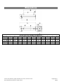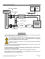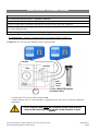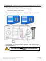
1
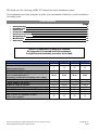
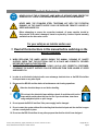
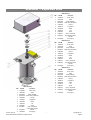
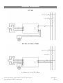
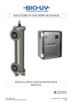
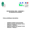
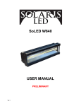
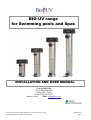
BIO-UV range for Swimming pools and Spas UV10 UV20 UV30 UV40 INSTALLATION AND USER MANUAL Company BIO-UV SA ZAC La Petite Camargue 34400 LUNEL - France Phone: +33 (0)4 99 133 911 www.bio-uv.com Email : [email protected] Gamme_Piscine_Monolampe_(Anglais_SansChimie).doc, version A, edition du 24/11/2011 Marque, Modèles et Brevets déposés – Modèles exclusifs Copyright BIO-UV Page 1/1 CERTIFICAT DE CONFORMITE CERTIFICATE OF CONFORMITY Ce certificat confirme que tous les appareils conçus et fabriqués par la société BIO-UV SA depuis le 01/06/2000 sont conformes a toutes les directives CEE particulièrement en matière de directives C.E.M et Electriques. This certificate confirm that all products manufactured by BIO-UV SA for sale after June 2000 will comply with the requirements of all relevant EEC directives. Specifically these include the E.M.C directive. Benoît GILLMANN Chairman and Managing Director of BIO-UV Company BIO-UV SA ZAC La Petite Camargue 34400 LUNEL - France Phone: +33 (0)4 99 133 911 www.bio-uv.com Email : [email protected] Gamme_Piscine_Monolampe_(Anglais_SansChimie).doc, version A, edition du 24/11/2011 Marque, Modèles et Brevets déposés – Modèles exclusifs Copyright BIO-UV Page 2/2 We thank you for choosing a BIO-UV ultraviolet water treatment system. Our equipment has been designed to offer you operational reliability in total confidence for many years. CONTENTS Page Safety Warning Exploded view Dimensions Standard installation Electrical Connections Wiring Diagram Maintenance Guarantees 4 5 6 7 8 10 11 12 The BIO-UV equipment is ready to be installed. No intervention is required inside the equipment. A simplified quick assembly procedure is provided. DESCRIPTION Maximum pressure in Use Maximum flow rate (m3/h) (after pressure losses) EXPOSITION TIME / secondes PERFORMANCE In millijoules at the actual flow rates recommended above. (mandatory standard for drinking water: 25mj) BALLAST LAMP (nomber and power) SERVICE LIFE of LAMPS OVERALL HEIGHT in cm DIAMETER of the UV CHAMBERS in cm WEIGHT POIDS (without water) kg INPUT/OUTPUT (diameter in mm) with Unions supplied Gamme_Piscine_Monolampe_(Anglais_SansChimie).doc, version A, edition du 24/11/2011 Marque, Modèles et Brevets déposés – Modèles exclusifs UV 10 3 Bar UV 20 3 Bar UV 30 3 Bar UV 40 3 Bar 7 12 20 25 2,8” 2,6” 2,3‘‘ 2,1‘‘ 30 mJ 30 mJ 30 mJ 30 mJ 1 1 x 33 W 13 000 h 42,6 15,4 4,3 1 1 x 55 W 13 000 h 69,6 15,4 6 1 1 x 87 W 13 000 h 94,2 15,4 8 1 1 x 10⁵ W 13 000 h 119,6 15,4 9,4 50 50 63 75 Copyright BIO-UV Page 3/3 Safety Warning NEVER LOOK AT THE ULTRAVIOLET LAMP WHEN LIT WITHOUT USING PROTECTIVE GOGGLES AS IT COULD CAUSE SEVERE INJURIES, BURNS OR EVEN BLINDNESS. NEVER UNDO THE STAINLESS STEEL TIGHTENING NUT WITH THE FILTRATION RUNNING, AS THE QUARTZ SLEEVE COULD BE EXPELLED FROM ITS HOLDER AT SPEED AND INJURE YOU Before attempting to access the connection terminals, all power supplies should be disconnected. If the cable is damaged, it must be replaced by a cable or special assembly available from the after-sales service. For your safety as an installer and/or user: 1. Read all the instructions in this manual before switching on the BIO-UV sterilizer 2. WHEN REPLACING THE LAMPS AND/OR DURING THE ANNUAL CLEANING OF QUARTZ SLEEVES, CHECK THAT THE ELECTRICAL PART IS IN PLACE AND CORRECTLY SECURED BEFORE SWITCHING ON THE STERILIZER. 3. CHECK THAT THE NUT, WASHER AND O-RING (16-15-14) ARE CORRECTLY POSITIONED, OTHERWISE THE QUARTZ SLEEVES COULD BE EXPELLED FROM THEIR HOLDER AT SPEED AND INJURE YOU. 4. In order to avoid electrical short-circuits, never submerge electrical wires or the BIO-UV sterilizer in the pool water or any other liquid 5. Disconnect the BIO-UV sterilizer before all maintenance and cleaning operations 6. 7. Allow the ultraviolet lamps to cool before handling DO not touch the ultraviolet lamps with bare hands. It would leave dirt on the lamps which would reduce their service life. If you touch them, clean them using methylated spirits or spirit vinegar 8. Do not operate the BIO-UV sterilizer if the power supply lead is damaged 9. Do not re-start the system without first checking that the electrical part and the sterilizer’s upper unit are correctly back in place 10. Do not use the BIO-UV sterilizer for any other purpose than that for which it was designed Gamme_Piscine_Monolampe_(Anglais_SansChimie).doc, version A, edition du 24/11/2011 Marque, Modèles et Brevets déposés – Modèles exclusifs Copyright BIO-UV Page 4/4 Sterilizer – Exploded view REACTOR UV 10 REP Ref PMI Description 3 JTS003934 Quartz_Guide 5 PIE001949 Switch 6 BAL001422 Ballast_lw20eb65 7 QUA000016 Quartz sleeve_d25x594mm 8 LPE000003 UV Lamp 9 JTS000100 O-ring Ø25x5 10 PIE000659 Washer 11 USI000018 Nut 12 ELE000001 Socket 13 ELE000311 14 ELE000817 15 ACC000967 Carter_174x249x100 Lamp operating indicator with LED Grounding lug REP Ref PMI Description 3 JTS003934 Quartz_Guide REACTOR UV 20 5 PIE001949 Switch 6 BAL000025 Ballast_lw20eb65 7 QUA000017 Quartz sleeve_d25x594mm 8 LPE000004 UV Lamp 9 JTS000100 O-ring Ø25x5 10 PIE000659 Washer 11 USI000018 Nut 12 ELE000001 Socket 13 ELE000311 Carter_174x249x100 Lamp operating indicator with LED Grounding lug 14 ELE000817 15 ACC000967 REP Ref PMI Description 3 JTS003934 Quartz_Guide 5 PIE001949 Switch REACTOR UV 30 REACTOR UV 40 REP Ref PMI Description 3 JTS003934 Quartz_Guide 5 PIE001949 Switch 6 BAL000026 Ballast_lw20eb65 7 QUA000019 Quartz sleeve_d25x594mm 8 LPE000006 UV Lamp 9 JTS000100 O-ring Ø25x5 10 PIE000659 Washer 11 USI000018 Nut 12 ELE000001 Socket 13 ELE000311 Carter_174x249x100 Lamp operating indicator 14 ELE000817 with LED 15 ACC000967 Grounding lug Gamme_Piscine_Monolampe_(Anglais_SansChimie).doc, version A, edition du 24/11/2011 Marque, Modèles et Brevets déposés – Modèles exclusifs 6 BAL000026 Ballast_lw20eb65 7 QUA000018 Quartz sleeve_d25x594mm 8 LPE000005 UV Lamp 9 JTS000100 O-ring Ø25x5 10 PIE000659 Washer 11 USI000018 Nut 12 ELE000001 Socket 13 ELE000311 14 ELE000817 15 ACC000967 Carter_174x249x100 Lamp operating indicator with LED Grounding lug Copyright BIO-UV Page 5/5 Dimensions Model UV 10 UV 20 UV 30 UV 40 A B 426 696 942 1196 275,5 545,5 771.5 1025,5 DIMENSIONS in mm (excepted K) C D E F G H 2133 483 689 943 62,5 62,5 82,5 82,5 313 583 829 1083 154 154 154 154 Gamme_Piscine_Monolampe_(Anglais_SansChimie).doc, version A, edition du 24/11/2011 Marque, Modèles et Brevets déposés – Modèles exclusifs 223 223 228 233 108 108 113 118 I J K 249 249 249 249 174 174 174 174 1"1/2 1"1/2 2" 2"1/2 Copyright BIO-UV Page 6/6 Standard Installation BIO-UV DOSING PUMP Ø50 ou 63 ou 75 UNION BIO-UV pH REGULAT OR INJECTION BIO-UV BY-PASS VALVE pH PROBE HEATING BY-PASS VALVE FILTRE PUMP SWIMMIN G POOL BY-PASS VALVE RECOMMANDATIONS Install the BIO-UV equipment in the equipment room, respecting the 0.1 and 2 safety areas around the volume in accordance with the current installation rules (NF C15100) Unless the equipment is dismantled in order to change the lamps and clean the quartz sleeves, leave enough room to remove the lamps – the AVAILABLE HEIGHT in the equipment room must be DOUBLE the total size of the equipment The BIO-UV equipment must be installed on the discharges after the filter and before the heater (where applicable). The equipment’s water inlet should preferably be at the bottom and, thus, its outlet to the pool at the top. (If necessary it can be positioned horizontally). The unions provided for ease of fitting and dismantling are supplied with either a 50 mm (UV10 & 20), 63 mm (UV30) or 75 mm diameter (UV40). If a bypass is used for the heating, the BIO-UV equipment should be installed before the bypass Using clamping collars (50, 63 or 75 mm diameter) secure the REMANENT and pH liquid injectors and pH analysis probe in the correct order, see diagram above. Gamme_Piscine_Monolampe_(Anglais_SansChimie).doc, version A, edition du 24/11/2011 Marque, Modèles et Brevets déposés – Modèles exclusifs Copyright BIO-UV Page 7/7 ELECTRICAL CONNECTIONS IMPORTANT The connections must be made by a qualified technician. A 30mA differential circuit breaker must be present and a fuse or a circuit breaker must be installed. The power supply must correspond to that shown on the label on the side of the equipment. The power supplied to the pH regulator must be servo-controlled by the filtration. (See wiring diagram below). Before making the connections, switch off the power supplies. 1°/ General case : you have a contactor with a coil supplied with 220-240Vac : Connect the UV reactor to the filtration unit as shown below: Filtration contactor Timer Earth = Green/ Yellow Pump … L = Live = Brown (220-240Vac) N = Neutral = Blue • Connect the UV reactor to the contactor coil. • Check that the fuse or circuit breaker is appropriate for the power of all the connected equipment. The UV reactor must never be connected to the same terminal strip as the filtration pump(s) and/or to the boosters in your system. Gamme_Piscine_Monolampe_(Anglais_SansChimie).doc, version A, edition du 24/11/2011 Marque, Modèles et Brevets déposés – Modèles exclusifs Copyright BIO-UV Page 8/8 2°/ Particular case : you have a contactor with a coil not supplied with 220-240Vac : • Take a relay (not provided) which must : - have the same tension on its coil as on the contactor coil, - allow at least 5 amperes on its contacts. • Connect the UV reactor with the adviced relay as shown on the drawing below: Relay Filtration Timer Earth = Green/ Yellow Pump … L = Live = Brown (220-240Vac) N = Neutral = Blue • Check that the fuse or circuit breaker is appropriate for the power of all the connected equipment. The UV reactor must never be connected to the same terminal strip as the filtration pump(s) and/or to the boosters in your system. Gamme_Piscine_Monolampe_(Anglais_SansChimie).doc, version A, edition du 24/11/2011 Marque, Modèles et Brevets déposés – Modèles exclusifs Copyright BIO-UV Page 9/9 WIRING DIAGRAM UV 10 I ON/OFF SWITCH OPERATING INDICATOR LIGHT UV 20 – UV 30 – UV40 ON/OFF SWITCH OPERATING INDICATOR LIGHT N = Neutral / L = Live / PE = Earth Gamme_Piscine_Monolampe_(Anglais_SansChimie).doc, version A, edition du 24/11/2011 Marque, Modèles et Brevets déposés – Modèles exclusifs Copyright BIO-UV Page 10/10 Maintenance (See exploded view on p6-7) The ultraviolet lamps are designed to last for 13,000 hours or be switched on 1,000 times, i.e. approximately 2 years for a seasonal outdoor pool, or 1 year for an indoor pool operating 24 hours a day. In order to prevent premature wear, it is recommended that they be switched on (i.e. 1 filtration cycle) once a day which will also preserve the filtration pump. Cleaning the quartz sleeve: Changing the lamp: Dismantling the quartz sleeve It is essential to work with the lamp off and the filtration stopped. Whether the equipment is installed vertically or horizontally, check that there is sufficient space to remove the lamp in the equipment room. Disassembly (see part numbers on the diagram on page 7-8) - Remove the unit (22). - Take hold of the 4-pin connector (21) and gently pull the lamp upwards rotating it. - As soon as the lamp is a few centimetres out, remove the connector, take hold of the ceramic base and disengage the lamp from the quartz sleeve keeping it correctly in the axis. - Carry out the operation with care. Do not drop the lamp in the quartz sleeve as it could break and damage the quartz. Re-assembly - Take hold of the new lamp, avoiding touching it with bare fingers outside the upper and lower ceramic bases (if you do touch it, clean it with a soft cloth using methylated spirits). - Engage the lamp in the quartz sleeve, keeping it correctly in the axis, inside the equipment. - Having engaged it ¾ of the way in, connect up the lamp using the connector (21) on the lamp’s 4 pins, making sure you get it the right way round (locating pin). Do not force it. - Engage the lamp fully inside the quartz sleeve. - Refit the unit (22). Every year you must check that the quartz sleeve has not become opaque due to scale deposits. It should be completely transparent so as not to reduce the amount of UV radiation passing through it. - Stop the filtration and work with the lamps off. - Close all the valves on the installation. WARNING: they are not guaranteed against breakage. - Remove the lamp (see previous paragraph). - Place it on a soft surface where it cannot get broken. - Undo the stainless steel nut by hand (16) - Remove the plastic washer (15), - Insert your thumb or a finger into the sleeve, and gently slide it until the O-ring (14) disengages from its housing. - Take hold of the quartz sleeve in order to fully extract it from the equipment ensuring that it remains aligned with the equipment’s axis. If the sleeve is clean and completely transparent: reassemble it in accordance with the instructions below. If whitish calcium deposits are present, you must clean it. This is done using spirit vinegar or acid and a soft cloth. The quartz must not be scratched as this would change the ultraviolet radiation qualities. ReRe-assembling the quartz sleeve: - Carefully insert the sleeve in the equipment, keeping it aligned with the equipment’s axis. - Using your finger inside the sleeve, position the quartz in its holder at the bottom of the equipment. The quartz should protrude slightly (by the thickness of the Oring), it should not fall right to the bottom. If the quartz is correctly positioned in the holder, when it is pressed it feels springy (pneumatic effect). - Position the O-ring (14) around the sleeve having moistened it beforehand. Push it fully into its housing using your nail (do not use any tools). - Place the plastic washer (15) inside the stainless steel thread. - Retighten the stainless steel nut (16) by hand, tightening normally. - Refit the lamp (see previous paragraph). - Refit the unit (22). - Reconnect. Gamme_Piscine_Monolampe_(Anglais_SansChimie).doc, version A, edition du 24/11/2011 Marque, Modèles et Brevets déposés – Modèles exclusifs Copyright BIO-UV Page 11/11 Guarantees The guarantee for the BIO-UV equipment range applies as follows: - 5 years for the stainless steel reactor (materials and weld) other than in the case of use in a highly corrosive environment (brackish or very salty environment, e.g.: seawater), - 2 years for all other components, except for the UV lamp (13 000 hours, depending on the number of switchings on/off) The electrical components are not guaranteed against over-voltages or lightning damage. Warning! The quartz sleeves and lamps are not guaranteed against breakage. - Any defective parts should be returned, giving details of the type and serial number of the equipment, to BIO-UV who will replace it after technical survey. - Postage costs will be shared between the retailer and BIO-UV. - The guarantee comes into force on the day the equipment is installed: this date shall be communicated to BIO-UV by returning the completed guarantee validation (see next page) by mail or fax. Warning: If the guarantee validation is not returned within 3 months of the equipment being purchased, BIO-UV will assume that the guarantee’s effective date is the month and year of its manufacture. In the event that the equipment is not installed in accordance with the installation instructions and user manuals, BIO-UV will not accept any responsibility and the guarantees will be null and void. Conclusion The BIO-UV system produces unequalled water quality, comfort and peace of mind. Simple to use, and with reduced maintenance and after-sales service, in order to optimise its reliability. This physical water treatment, using UV-C radiation, offers an environmentally friendly concept with no chemical residue toxic for either humans or nature. The BIO-UV team is at your disposal Company BIO-UV SA ZAC La Petite Camargue 34400 LUNEL France Phone: +33 (0)4 99 133 911 www.bio-uv.com Email : [email protected] Gamme_Piscine_Monolampe_(Anglais_SansChimie).doc, version A, edition du 24/11/2011 Marque, Modèles et Brevets déposés – Modèles exclusifs Copyright BIO-UV Page 12/12