1
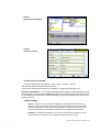
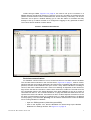
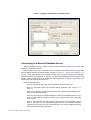
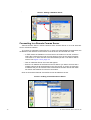
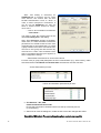
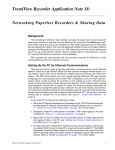
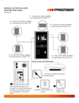
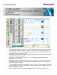
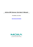
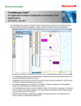
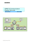
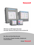
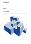
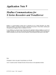
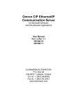
X Series & V5 Application Note 18:
Networking Paperless Recorders & Sharing Data
Background
The networking of electronic data recorders provides the opportunity to share data with
other users, whether in real time or as an electronic file. Using the TrendManager Software Suite makes this easy to do. TrendServer Pro (TSP) allows the user to share data
files by exporting the data in CSV (comma separated variable) format to third party software
packages like Microsoft Excel or Lotus 123. TSP takes this to the next level by allowing the
user to set up a Client-Server network, allowing multiple clients to view data from a server
PC running TSP software in real time or from a database.
TSP operates and communicates with the recorders using the PC Ethernet or Serial
communications port for the network connection.
Setting Up the PC for Ethernet Communications
There are two common types of topology used when connecting devices into an Ethernet
network. These are a star network, where a central computer manages network access, or a
ring network, where users on the network can establish direct connections with other workstations. The TSP and recorders use a star network topology. Because TSP uses this type
of topology, the communications server within TSP is designed so only one TSP communications server is able to access the recorders on the network at a time; otherwise there
would be timing and collision issues. Because the Ethernet TCP/IP network uses a shared
communications channel that is passive in nature; the Ethernet standard prescribes the
rules needed to manage the nodes as they contend for the use of the network, since there is
no central communications device to do this. Multiple users can view client data through distributed communications and view the data through the Server PC. The set up to use when
viewing data on multiple PC’s is as follows: (see Figure 1, “Local Area Network,” on
page 2)
To set up the PC for this use the following the steps.
1.
Set up the PC Network Neighbourhood Properties for the TCP/IP Protocol along with
the appropriate IP Address, Subnet Mask and Default Gateway, refer to “Appendix
A – Access to PC Communication Parameters” on page 14 for further details.
2.
Designate a single PC as the archive for the data in TSP under logging (in this case
TrendServer1, Figure 1, “Local Area Network,” on page 2)
3.
Setup TSP on that PC; enable the Communication Server to initiate data retrieval
and logging of data to that PC, see “Setting Up Ethernet Communications in
TrendServer Pro” on page 6.
4.
On each of the other network PC’s (Clients) that you want to be able to see the data
on, enable DCOM on each of these PC’s as well as the archive data PC. The DCOM
(Distributed Component Object Model) is a Microsoft product that is part of the Windows™ operating systems that allow sharing of application specific data across the
network. Refer to “DCOM Configuration” on page 15 for further details
43-TV-07-18 GLO Issue 3 Nov 07 UK
1
5.
Once you have DCOM enabled on each network node, you can then select the
"servers" tab in TSP and connect to a remote server by adding the IP address of
the designated archive PC. The data on the archive PC will be viewable from the
network node PC.
FIGURE 1.
Local Area Network
There are a number of parameters that must be set up in the PC in order to start real
time communications with the recorders over the Ethernet network. These settings vary
slightly depending on the operating system installed (Windows™ 2000/XP service pack2)
on the PC, but the settings are generally found under the Network Neighbourhood icon. In
many cases, changes in these settings must be cleared with the IT Department, especially
if the PC is connected to the plant-wide network. The PC’s TCP/IP parameters needing to
be set include:
2
§
IP Address for the PC
§
Subnet Mask (must match the subnet mask programmed for the recorders)
§
Default Gateway
§
DCOM (Distributed Communications)
43-TV-07-18 GLO Issue 3 Nov 07 UK
Comms Server
A dedicated PC can be allocated to run the Comms Server only, without TSP. Should the
power fail followed by power up the Comms Server will start up after any required login and
resume communications without having to manually restart TSP.
In order to run Comms Server and the Database server at Startup without TSP a shortcut must be put onto the Startup folder
• First create the Shortcut in the CommsSrv.exe installation location (eg.C:\Program Files\TrendManager Suite\TrendServer\CommsSrv.exe). To do this right
click on “CommsSrv.exe” and select Create Shortcut.
• Copy the Shortcut into the Startup folder.
• The Startup folder can be found by going to the Start button on the bottom left
of the PC screen.
• Select Programs from the list and then select Startup.
Copy the Shortcut to CommsSrv.exe
to the Startup folder
Setting Up Ethernet Communications in the Recorder
TSP uses the Trendbus protocol over an Ethernet link for realtime communications with
V5 version recorders and Modbus for realtime communications with X-Series recorders;
Realtime communications allows data to be instantaneously displayed on a PC and logged
to the local PC’s database. Other remote PC’s can view the data stored in this database.
Once the local PC has been set up for communications, the recorder(s) must also be set up
to match the network requirements for Recorder ID, Communication Port, IP Address, Subnet Mask, Default Gateway, and Protocol. These parameters are set up as part of the General Configuration parameters using the Recorder’s Comms and Factory menus, see
Figure 2 on page 4.
43-TV-07-18 GLO Issue 3 Nov 07 UK
3
FIGURE 2.
V5 Recorder IP Address
FIGURE 3.
X Series recorder
For the X Series recorder
Follow the Main Menu >Configure > Setup > Edit > Comms > TCP/IP.
Transmission Control Protocol/Internet Protocol.
A protocol for communication between computers, recorders and other devices.
Automatic DNS Names - The recorder will automatically register a unique Network ID using
the serial number. The format is xs-nnnnnn, where nnnnnn is the serial number of the recorder. This allows you to locate the recorder for browsing if you are using DHCP (Dynamic Host Configuration Protocol).
TCP/IP Settings
• Static IP - Toggle On and Off. With this enabled the IP address will be the same every
time the recorder is powered up. With this feature Off, the recorder’s IP address is created
dynamically using a DHCP (Dynamic Host Configuration Protocol) Server. With this feature On the IP address can be fixed by entering a known available IP address below.
• IP Address - (Available when Static IP is On). This is an identification address for communications between two devices. The IP Address identifies a specific recorder.
4
43-TV-07-18 GLO Issue 3 Nov 07 UK
• Sub Net Mask - (Available when Static IP is On). Acts as a filter when identifying an IP
address
• Gateway - (Available when Static IP is On). A configuration parameter transmitted to each
network device
• DNS/WINS/MDNS - Set to Automatic, click on this to activate and de-activate options. DNS
= Domain Name System, WINS = Windows™ Internet Name Service, MDNS = Managed
Data Network Services. See “DNS/WINS/MDNS” on page 5.
• Ports - The Port numbers are associated with the IT system in use. Port numbers are set to
a default but can be changed by the user to allow data traffic to use a specified port. See
“Ports” on page 5.
DNS/WINS/MDNS
(Main Menu > Configure > Setup > Edit Setup > Comms > TCP/IP > DNS/WINS/MDNS)
Set to Automatic, click on this to activate and de-activate options. DNS = Domain Name System, WINS = Windows™ Internet Name Service, MDNS = Managed Data Network Services.
• Auto DNS - This is a sub menu for DNS/WINS/MDNS. Toggles On and Off. With this deactivated the DNS Server address can be changed from the default, if required.
• Pri. DNS Address - This is a sub menu for DNS/WINS/MDNS. Only available when Auto
DNS is deactivated.
• Sec. DNS Address - This is a sub menu for DNS/WINS/MDNS. Only available when Auto
DNS is deactivated.
• Auto WINS - This is a sub menu for DNS/WINS/MDNS. Toggles On and Off. With this
deactivated the Windows™ Internet Name Service can be changed from the default, if
required.
• Pri. WINS Address - This is a sub menu for DNS/WINS/MDNS. Only available when Auto
WINS is deactivated.
• Sec. WINS Address - This is a sub menu for DNS/WINS/MDNS. Only available when Auto
WINS is deactivated.
• Auto MDNS - This is a sub menu for DNS/WINS/MDNS. Toggles On and Off. This will
deactivate the Managed Data Network Services.
When the setup is complete go back to the TCP/IP menu and complete the setup.
Ports
The port numbers are associated with the IT system in use. Port numbers are set to a default
but can be changed by the user to allow data traffic to use a specified port.
• HTTP - HyperText Transport Protocol is the communications protocol that enables Web
browsing. Select and enter the desired port number if required. (Defaults to 80)
• Modbus - communications protocol used for automation applications. Select and enter the
desired port number if required. (Defaults to 502)
When the setup is complete go back to the TCP/IP menu to complete further Comms setup.
When the configuration is complete select the Finish button to Commit, Discard or Commit Later. Select the Back button to return to the previous menu.
43-TV-07-18 GLO Issue 3 Nov 07 UK
5
Setting Up Ethernet Communications in TrendServer Pro
TSP is designed with three basic modules, plus the ability to import recorder data and
configurations, as shown below. The Communications Server (3) is the critical piece used
for setting up and managing the communications with devices connected on the network.
The Database Server (2) manages the acquired data and is used to make it available to
other applications. The third piece is the Display Generator (1) that handles the displaying
of the data on the PC and the Printing, Import and Configuration portions which all reside in
the TSP software.
FIGURE 4.
TSP Ethernet Communication
DCOM
2
3
1
The Comms Server and Database Server are displayed as icons in the lower right hand
corner of the Windows™ Task bar. Left clicking or double clicking on the icon allows the
Comms Server to be opened so the communications ports can be set up.
All Comms activity, both Logging and Realtime, can be viewed on the Comms Server
FIGURE 5.
Database & Comms Servers
Database & Comms
Server icons
Comms Server
opened showing
Communications
ports, COM1 to COM8
and Ethernet.
6
43-TV-07-18 GLO Issue 3 Nov 07 UK
COM1 through COM8, Figure 5 on page 6, are used to set up the recorders on a
RS485 network, the Ethernet selection is used to set up any recorders on the Ethernet link
(Select Communications Ports to enable Ethernet, shown active by a Red tick). Left click on
“Ethernet” and it opens a window allowing you to view the status of recorders that may
already be set up, to add a recorder or to configure the logging for any particular recorder.
The Comms Server window is shown below:
FIGURE 6.
Communications Server
Real-time communications
For Realtime communications to occur, at least one Pen on a recorder must be enabled.
The recorder status indicators in the Comms Server, Figure 6 on page 7, must be ‘Green’
signifying that the local network addressing and set ups are compatible and that the recorder
protocol, recorder ID and hardware set up is correct. “Grey” status indicates it is waiting to
connect, and red is a failed connection. If this is not working as expected, review all the settings for the PC and the recorders. A basic check would be to “PING” the recorder from the
PC’s Command prompt. This would determine if the basic hardware is set up to receive a
command from the PC. The command would be C:>ping XXX.XXX.XXX.XXX where the X’s
represent the device IP address. If this does not return a valid response but times out, there
are basic communications issues at a network level (i.e. cable wrong/defective, IP address
not set properly). The command “ipconfig” can be used to determine the current IP address
for PC’s using Windows™ 2000/XP.
• Open the TSP application (START/Programs/TSP )
• Click on the ‘System” icon, then the Realtime icon which brings up the Default
Realtime Pen Settings window. See Figure 7 on page 8.
43-TV-07-18 GLO Issue 3 Nov 07 UK
7
• Set the Data rate, Data Type (Sample or Min/Max), Events. Click OK and
close the Servers list.
• From the left hand menu bar click on the ‘Realtime’ button to display the
Recorders list. Click on the Comms Servers tab to see the available Comms
Servers that are connected. Select the Comms Server you wish to connect to.
See Figure 7 on page 8.
FIGURE 7.
Realtime Pen Settings and Realtime Comms Server list in TSP
• Open the Comms Server by clicking on the Comms Server icon in the task bar
at the bottom right of your PC screen.
• Right click on the Ethernet listing to add a new recorder or select the desired
recorder if it is already set up and appears in the list of recorders
Comms Logging (as for Realtime Comms, plus..)
• From the Comms Server, select the Logging Configuration option by right
clicking on the desired recorder
• Set up the Pens to be logged from the available list
• Set the Pen Logging rates and Type of Logging (Sample or Min/Max)
• The logging rates can be set independently for each pen
• Once these items are configured the Comms Server can be minimized (shutting down the Comms Server will stop communications).
8
43-TV-07-18 GLO Issue 3 Nov 07 UK
FIGURE 8.
Logging Configuration in Comms Server
Connecting to a Remote Database Server
“Remote Database Server” means someone else’s Database Server on a Local Area
Network or a Remote network.
TSP can also be set up to view data from a remotely connected PC that is logging data
from recorders that are connected locally to that PC. (Figure 1, “Local Area Network,” on
page 2). This requires TSP to be installed on both PC’s and to be actively collecting data;
DCOM must also be configured on both PC’s to allow this distributed communications and
remote viewing of the data. Once DCOM has been configured on the PC’s, open TSP ; this
allows you to set a link to the other PC.
Use the following steps:
• Click on the ‘Server’ icon; this opens a window to add a new server
• Click on Add New Server (the window below appears). See Figure 9 on
page 10.
• Enter the IP address of the Remote Server and a Name for identification purposes in the space provided
• Once this is entered, the name will appear in the list of available servers, if it is
active on the network, it should connect to the remote server (this could take
time to occur.
• Click on the Recorder icon and drag the recorder onto the trend display (graph
area to the right) to view Historical/Logged data for the recorder from this
remote server (shown as blue scale indicators for comms logged data and
white scale indicators for disk data).
43-TV-07-18 GLO Issue 3 Nov 07 UK
9
)
FIGURE 9.
Adding a Database Server
Connecting to a Remote Comms Server
“Remote Comms Server” means someone else’s Comms Server on a Local Area Network or a Remote network.
To connect to a Remote Comms Server, in order to access Realtime recorder data, the
IP address of the Remote Comms Server must be known and entered into TSP.
• In TSP, select the Realtime Icon from the list of buttons on the left, and then
select the Comms Servers tab, this will produce a list of the Servers already
connected. If no other servers have been added just the Local Server will be
shown. See Figure 10 on page 10.
• Click on Add New Server and a box will appear.
• Enter the IP Address of the Remote Comms Server you wish to access and a
suitable name that will be displayed in the Servers list. If you do not know the
IP address but you do have the name of the Remote Comms Server then TSP
will search the Network for servers of that name.
Click on OK and the Remote Comms Server will be added to the list.
FIGURE 10.
10
Adding a Communications Server
43-TV-07-18 GLO Issue 3 Nov 07 UK
• Click on the Realtime icon and drag the recorder onto the trend display to view
Realtime data for the recorder from this remote server. Realtime data is displayed with an orange scale.
• With the Remote Comms Server connected the Realtime data will begin to
graph on the screen.
Once this has been done, you are now viewing data as a remote client. Multiple Clients
can be set up to view the data on the server PC. These clients might represent the plant
manager, quality assurance, the engineering staff or other appropriate user that can connect
to the server PC. In each case, these users all need to have the DCOM setting enabled and
be running TSP.
TrendServer Pro Graphing
From the TSP Graph display, recorders can now be viewed on the trend display
• Click on the Realtime icon to display a list of recorders
• Select the desired recorder and drag it onto the graph to begin trending
• There are two areas on the TSP where recorder data can be displayed (Historical/Logged or Realtime)
FIGURE 11.
TrendServer Pro Graphing window
Logged Data
area
Realtime Data
area
Realtime Data = Orange scales,
Comms Logged Data = Blue scales
Disk Data = White scales (not shown)
43-TV-07-18 GLO Issue 3 Nov 07 UK
11
Summary
TSP provides great flexibility for setting up a communications network using Honeywell Paperless Recorders. TSP supports scheduled File Transfers using the FTP protocol,
real time communications with a single user or networking through a client-server arrangement allowing multiple users to view the data. TSP also provides an OPC Server function
allowing real time data acquisition to other HMI software packages that have an OPC Client. Getting everything correct in order to do communications over a network can be challenging, because many users are unfamiliar with setting up a network and in many cases it
is an area generally left to IT.
This application note helps provide the guidance necessary to get started; providing the
basic knowledge required for setting the parameters in the recorders and the PC for communications. Keep in mind, that in order for communications to work, many parameters are
involved and unfortunately they must all be correct. For that reason, a final checklist is provided below that you can use as a guide for checking and double-checking.
General Checklist
• IT permission to connect devices to the network
• Administrator permission to make changes in personal PC (if necessary)
• Operating System known as it does affect set ups (Windows™ 2000 or XP
service pack 2)
PC Checklist
• IP Address of the PC being used to run TSP.
• Is the IP Address in the same domain as the recorders IP address (are they
on the same virtual network?).
• Is the Subnet mask set correctly (should be the same as your recorder).
• Is the Default Gateway set correctly (should be the same as your recorder).
• Is DCOM enabled for doing distributed communications.
• Can the recorder be “ping-ed” to prove the hardware is set correctly.
• TSP is available.
Recorder
• Each recorder IP address will be unique. All recorders must have different IP
addresses than the other devices on the network.
• All IP addresses are unique but within the same network.
• The Subnet Mask is set correctly (should be the same as your PC).
• The Default Gateway is set correctly (should be the same as your PC).
• Each recorder has a unique non-zero Recorder ID set (such as recorder id
1001).
• The Factory Comms Ports (under General Set up) is enabled for Ethernet.
• The Protocol (under General Set up/Comms) is set for Trendbus for V5 type
recorders and Modbus or Modbus X for X-Series recorders.
• The Ethernet cable is connected to the proper PC and Recorder RJ 45 connection.
• If doing one on one Ethernet communications a crossover cable is being used.
12
43-TV-07-18 GLO Issue 3 Nov 07 UK
TrendServer Pro Software
• TSP is enabled, appropriate port has to be enabled, designated by a Red
check mark on the port on the Comms Server. See Figure 5 on page 6.
• The Comms Server is open (icon at bottom right on PC screen).
• Recorder with its ID shows up in list under Ethernet Communications Ports.
• The IP address for the recorder matches the IP address in the recorder.
• Logging has been enabled and at least one pen is actively being logged.
• Comms Server Status indicators Green.
• The Recorder of interest has been dragged onto the trend display for viewing.
Additional references of interest:
43-TV-07-06 V5 App Note 6 – Setting up Trendbus over Comms
43-TV-07-08 V5 App Note 8 – OPC Overview
43-TV-07-09 V5 App Note 9 – DCOM Configuration
43-TV-25-05 V5 eZtrend User Manual
43-TV-25-07 V5 Mini/Multi User Manual
43-TV-25-08 V5 Communications Manual
43-TV-07-33 X Series App Note 8– X Series DCOM Settings and XP Firewall
43-TV-07-34 X Series App Note 9 – Modbus Communications for X Series and TSP
43-TV-25-30 X Series - Product/User Manual
43-TV-25-11 V5 & X Series Software Manual - TrendManager Suite
43-TV-07-18 GLO Issue 3 Nov 07 UK
13
Appendix A –
Access to PC Communication Parameters
Networking these devices requires the proper configuration of a number of network
parameters. The PC parameters of interest are found in the “Network Neighbourhood” settings. This icon typically appears on the ‘desktop’ of the PC. If changes are going to be
made to any of these settings, the user will need to have access rights to make those
changes; if access is denied, then the IT (Information Technology) or LAN administrator will
need to be consulted. Also, before making any changes it is best to record the current settings, especially if you plan to put the PC back on the network. The PC windows that provide the access to these settings do vary depending on the Windows™ Operating system
being used; shown below are the screens from a Windows™ 2000 Operation system. To
access them, follow the steps listed:
1.
Select the Start button in the bottom left corner of the screen, select Settings from
the next menu and then Network and Dial-up Connection from the next. Right
click on the Local Area Connection displayed in the box and select properties
from the menu. The Local Area Connection Properties box is displayed. From
the list, select Internet Protocol (TCP/IP) and click on the properties button. The
Internet Protocol (TCPIP) Properties box is displayed.
(The PC windows shown below are for Windows™ 2000; other Operating Systems will
show similar information.)
14
2.
From these windows, you can see the current IP address, Subnet Mask and
Default Gateway for the PC that you will need for setting up the Recorders and
TSP software to make sure that the communications parameters are compatible.
3.
These parameters can be changed but care should be exercised since any
changes made can affect the ability to use the PC on the existing network.
4.
You can also check the Ethernet Adapter information as follows. Go to Start, Programs, Accessories, Command Prompt. At the command prompt type: IPCONFIG (this is a Windows™ NT/2000 utility).
43-TV-07-18 GLO Issue 3 Nov 07 UK
DCOM Configuration
The DCOM (Distributed Communications) setting needs to be enabled for all PC’s
(including the Server PC) running Trend Server Pro when remote servers are being used in
order to share data across the network. Details are provided below for enabling the DCOM
setting. There are some differences in enabling this feature depending on the Windows™
operating system being used.
DCOM is an integrated part of Windows™ Operating System and more in depth information can be found on Microsoft web sites.
1.
To begin click on the 'Start' button at the bottom left of the PC, select 'Run'. This will
open the dialog box, type: dcomcnfg and click OK
2.
For Windows™ 2000, Go to the Default Properties tab. Go to item 3. For Windows™ XP only, this will start ‘Component Services’.
Click on Component Services under the Console Root to expand it.
Click on Computers under Component Services to expand it.
Right click on My Computer in the pane on the right and select Properties.
Then go to the COM Security tab.
3.
Under the Default Properties tab set the following:
Enable Distributed COM on this computer - tick the box
Default Authentication Level - (None)
Default Impersonation Level - Identify
4.
Under the Default Security tab:
The user’s IT department may wish to limit the permission settings, shown below, to
selected users or groups of users. Since these settings are solely for applications
that use Microsoft’s COM, they present no major security issues so the ‘global’ settings, shown below, are usually acceptable.
Settings for Windows™ 2000
Default Access Permissions
Edit Default Ensure that 'Everyone' is in the list with 'Allow Access' (add it if not)
Default Launch Permissions Configure same as Default Access Permissions above.
Settings for Windows™ XP – Default COM Security (Service pack 2)
n the Comm Security tab note that there are four permissions configurations that need editing.
Edit the Limits for Access and Launch
• Access Permissions – Edit Limits... You need to check the Remote Access box
for the user labeled ANONYMOUS LOGIN in this dialog.
43-TV-07-18 GLO Issue 3 Nov 07 UK
15
Note: This setting is necessary for
OPCEnum.exe to function and for some
OPC Servers and Clients that set their
DCOM 'Authentication Level' to 'None' in
order to allow anonymous connections. If
you do not use OPCEnum you may not
need to enable remote access for anonymous users.
• Launch and Activation Permissions
– Edit Limits...
You need to check the remote boxes for the
user labeled Everyone in this dialog.
Note: Since Everyone includes all authenticated users, it is often desirable to add these
permissions to a smaller subset of users. One
suggested way to accomplish this is to create
a group named “OPC Users” and add all user
accounts to this group that will execute any
OPC Server or Client. Then substitute “OPC
Users” everywhere that Everyone appears in
these configuration dialogs.
• Edit Default Permissions for Access and Launch
For each user (or group) that participates in OPC communication (e.g. “OPC Users”), make
sure that both the Local Allow and Remote Allow check-boxes are both checked.
Access Permissions per user:
Launch and Activation permissions per user:
5.
For Windows™ NT, 2000
Under the Default Protocols tab:
Ensure that 'Connection-oriented TCP/IP' is at the top of the list (move it
up if necessary)
6.
Select OK to close the dialog box, restart the PC to have the changes take effect.
Copyrighted Materials. For more information please contact your supplier.
16
43-TV-07-18 GLO Issue 3 Nov 07 UK