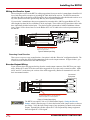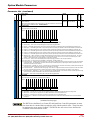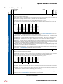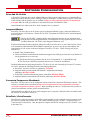
1
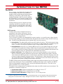
ADVANCED MICRO CONTROLS INC. User M Manual #: 940-0E012 al u n a GENERAL INFORMATION Important User Information The products and application data described in this manual are useful in a wide variety of different applications. Therefore, the user and others responsible for applying these products described herein are responsible for determining the acceptability for each application. While efforts have been made to provide accurate information within this manual, AMCI assumes no responsibility for the application or the completeness of the information contained herein. UNDER NO CIRCUMSTANCES WILL ADVANCED MICRO CONTROLS, INC. BE RESPONSIBLE OR LIABLE FOR ANY DAMAGES OR LOSSES, INCLUDING INDIRECT OR CONSEQUENTIAL DAMAGES OR LOSSES, ARISING FROM THE USE OF ANY INFORMATION CONTAINED WITHIN THIS MANUAL, OR THE USE OF ANY PRODUCTS OR SERVICES REFERENCED HEREIN. No patent liability is assumed by AMCI, with respect to use of information, circuits, equipment, or software described in this manual. The information contained within this manual is subject to change without notice. This manual is copyright 2013 by Advanced Micro Controls Inc. You may reproduce this manual, in whole or in part, for your personal use, provided that this copyright notice is included. You may distribute copies of this complete manual in electronic format provided that they are unaltered from the version posted by Advanced Micro Controls Inc. on our official website: www.amci.com. You may incorporate portions of this documents in other literature for your own personal use provided that you include the notice “Portions of this document copyright 2013 by Advanced Micro Controls Inc.” You may not alter the contents of this document or charge a fee for reproducing or distributing it. Standard Warranty ADVANCED MICRO CONTROLS, INC. warrants that all equipment manufactured by it will be free from defects, under normal use, in materials and workmanship for a period of [18] months. Within this warranty period, AMCI shall, at its option, repair or replace, free of charge, any equipment covered by this warranty which is returned, shipping charges prepaid, within eighteen months from date of invoice, and which upon examination proves to be defective in material or workmanship and not caused by accident, misuse, neglect, alteration, improper installation or improper testing. The provisions of the "STANDARD WARRANTY" are the sole obligations of AMCI and excludes all other warranties expressed or implied. In no event shall AMCI be liable for incidental or consequential damages or for delay in performance of this warranty. Returns Policy All equipment being returned to AMCI for repair or replacement, regardless of warranty status, must have a Return Merchandise Authorization number issued by AMCI. Call (860) 585-1254 with the model number and serial number (if applicable) along with a description of the problem during regular business hours, Monday through Friday, 8AM - 5PM Eastern. An "RMA" number will be issued. Equipment must be shipped to AMCI with transportation charges prepaid. Title and risk of loss or damage remains with the customer until shipment is received by AMCI. 24 Hour Technical Support Number 24 Hour technical support is available on this product. If you have internet access, start at www.amci.com. Product documentation and FAQ’s are available on the site that answer most common questions. If you require additional technical support, call (860) 583-7271. Your call will be answered by the factory during regular business hours, Monday through Friday, 8AM - 5PM Eastern. During non-business hours an automated system will ask you to enter the telephone number you can be reached at. Please remember to include your area code. The system will page an engineer on call. Please have your product model number and a description of the problem ready before you call. We Want Your Feedback Manuals at AMCI are constantly evolving entities. Your questions and comments on this manual are both welcomed and necessary if this manual is to be improved. Please direct all comments to: Technical Documentation, AMCI, 20 Gear Drive, Terryville CT 06786, or fax us at (860) 584-1973. You can also e-mail your questions and comments to [email protected] ADVANCED MICRO CONTROLS INC. Table of Contents General Information Important User Information ..................... Standard Warranty ................................... Returns Policy .......................................... 24 Hour Technical Support Number ........ We Want Your Feedback ......................... Specifications 2 2 2 2 2 About this Manual Audience .................................................. Trademark Notices ................................... Revision Record ....................................... Previous Revisions ........................ 5 Navigating this Manual ............................ Manual Conventions ................................ Where To Go From Here ......................... 5 5 5 5 6 6 Introduction to the RD750 The RD750 ............................................... 7 R-D Converter ............................... 7 Encoder Output .............................. 8 Software Configuration ................. 8 Notes on Reversing Count Direction ............... 9 Status LED’s .................................. 10 LED1: Host Drive Connection State .............. 10 LED2: Resolver State ....... 11 Compatible Sensors ................................. 12 Resolver Transmitters ....... 12 Resolver Control Transformers .................... 12 Single and Multi-Speed Resolvers ......................... 13 Resolver Tracking Speed ............................... 13 Specifications ............................................ 14 Installing the RD750 Setting Encoder Jumper and DIP Switches 15 RD750 Orientation ........................ 15 Setting the Encoder Jumper .......... 15 DIP Switch Settings ...................... 16 Settings for Common Resolvers ... 17 Determining Settings for Other Resolvers .................................... 17 Frequency Setting ......................... 17 TR Setting for Transmitter Resolvers .................................... 18 TR Setting for Control Transformer Resolvers ............... 18 Installing the RD750 ................................ 19 Wiring the Resolver Input ........................ 20 Reversing Count Direction ........... 20 Encoder Output Wiring ............................ 20 Determining the TR Setting of a Control Transformer Resolver ............... 21 With a True RMS Meter or Scope ...................................... 21 With the Resolver Status LED (LED2) ........................................ 21 Option Module Parameters Parameter List .......................................... 22 Troubleshooting Faults and Alarms .................................... 25 Software Configuration Drive Add On Profiles ............................. Integrated Motion ..................................... Connected Components Workbench ........ DriveTools / DriveExecutive ................... 20 Gear Drive, Plymouth Ind. Park, Terryville, CT 06786 Tel: (860) 585-1254 Fax: (860) 584-1973 http://www.amci.com 26 26 26 26 3 Table of Contents Notes 20 Gear Drive, Plymouth Ind. Park, Terryville, CT 06786 Tel: (860) 585-1254 Fax: (860) 584-1973 http://www.amci.com 4 ABOUT THIS MANUAL Read this chapter to learn how to navigate through this manual and familiarize yourself with the conventions used in it. The last section of this chapter highlights the manual’s remaining chapters and their target audience. Audience This manual explains the set-up, installation, and operation of AMCI’s RD750 Resolver Feedback Option Module for the Allen-Bradley PowerFlex 750-Series AC Drives. It is written for the engineer responsible for incorporating these modules into a design, as well as the engineer or technician responsible for its actual installation. Trademark Notices The AMCI logo is a trademark of Advanced Micro Controls Inc. All other trademarks contained herein are the property of their respective holders. Revision Record This manual, 940-0E012, is the third release of this manual. It adds additional information on the encoder emulator and its outputs. It was initially released on September 16th, 2013. Previous Revisions 940-0E011: Second Release. 9/3/2013. Added information on using control transformer resolvers. 940-0E010: Initial Release. 8/15/2013. Navigating this Manual This manual is designed to be used in both printed and on-line formats. Its on-line form is a PDF document, which requires Adobe Acrobat Reader version 7.0+ to open it. Bookmarks of all the chapter names, section headings, and sub-headings were created in the PDF file to help navigate it. The bookmarks should have appeared when you opened the file. If they didn’t, press the F5 key on Windows platforms to bring them up. Throughout this manual you will find blue text that functions as a hyperlink in HTML documents. Clicking on the text will immediately jump you to the referenced section of the manual. If you are reading a printed manual, most links include page numbers. You will also find red text that functions as a hyperlink. These links will bring you to the AMCI website. Note that after clicking on a red link, the program may ask for confirmation before connecting to the Internet. The PDF file is password protected to prevent changes to the document. You are allowed to select and copy sections for use in other documents and, if you own Adobe Acrobat version 7.0 or later, you are allowed to add notes and annotations. 20 Gear Drive, Plymouth Ind. Park, Terryville, CT 06786 Tel: (860) 585-1254 Fax: (860) 584-1973 http://www.amci.com 5 ABOUT THIS MANUAL Manual Conventions Three icons are used to highlight important information in the manual: NOTES highlight important concepts, decisions you must make, or the implications of those decisions. CAUTIONS tell you when equipment may be damaged if the procedure is not followed properly. WARNINGS tell you when people may be hurt or equipment may be damaged if the pro- cedure is not followed properly. The following table shows the text formatting conventions: Format Description Normal Font Emphasis Font Font used throughout this manual. Font used the first time a new term is introduced. When viewing the PDF version of the manual, clicking on the cross reference text jumps you to referenced section. When viewing the PDF version of the manual, clicking on the HTML reference text will open your default web browser to the referenced web page. Cross Reference HTML Reference Where To Go From Here This manual contains information that is of interest to everyone from engineers to operators. The table below gives a brief description of each section’s contents to help you find the information you need to do your job. 6 Section Title Starting Page Introduction to the RD750 7 Specifications 14 Installing the RD750 15 Option Module Parameters 22 Troubleshooting 25 Software Configuration 26 Intended Audience Anyone new to the RD750 Resolver Feedback Option Module. This section gives a basic overview of the features available on the unit and status LED blink patterns. Specifications table for the RD750. Anyone that must install an RD750. Includes information on DIP switch settings, mounting, grounding, and wiring. Anyone that needs a listing of the parameters available when using the 20-750-ENC-1 software profile and how the RD750 uses these settings. Anyone that needs a listing of the fault codes available when using the 20-750-ENC-1 software profile and when the RD750 will generate these codes. Anyone that needs basic information on the Rockwell Automation software packages that can be used to configure a PowerFlex 750Series AC Drives with an RD750. ADVANCED MICRO CONTROLS INC. INTRODUCTION TO THE RD750 The RD750 For over twenty years, Rockwell Automation and Advanced Micro Controls Inc. have partnered together to offer the most advanced sensor interface technology on the market. Based on this long standing relationship, AMCI is proud to announce the first and only resolver interface module for the PowerFlex 750-Series AC Drives from Rockwell Automation. Utilizing advanced resolver to digital conversion technology, the RD750 can interface with a wide variety of resolvers, including those from AMCI, Moog, Reliance, and Tamagawa, as well as many others. R-D Converter The heart of the resolver-to-digital converter is a monolithic IC that utilizes a ratiometric, Type II tracking loop converter for high speed data acquisition without velocity induced errors. To be as accurate as possible, the monolithic R/D converter requires a very specific return voltage from the sine and cosine windings, as well as minimal phase shift between the reference voltage and these return signals. The RD750 has additional hardware to guarantee R/D conversion accuracy. Analog Buffer: The analog buffer presents a specific load to the resolver. This load prevents the mag- netic cores of the resolver from saturating if it is operated at a voltage higher than its published specification. (A resolver can always be operated at a lower voltage without accuracy concerns.) Analog Multiplier: On power up, or when the RD750 receives a reset signal from the drive, the card reads the sine and cosine return voltages multiple times for approximately sixty milliseconds. With these readings, the RD750 calculates the proper coefficient for an analog multiplier that adjusts the sine and cosine signals so they are optimized for the monolithic R/D converter. Phase Compensator: The readings that are used to set the analog multiplier are also used by the RD750 to determine the phase shift between the reference voltage and the return signals. Once this value is known, the RD750 generates a second reference signal that is identical in frequency to the first reference, but phase shifted by the proper amount. The first reference voltage signal drives the resolver. The second reference is fed into the R/D converter. To the R/D converter, the reference and return signals appear to be in phase, yielding a more accurate conversion. The RD750 offers multi-turn position feedback with a single turn position resolution of up to 65,536 counts per turn and a tracking rate of up to 150,000 RPM. In addition to the single resolver interface, the RD750 offers an A/B quadrature output with Z pulse, powered by differential output drivers. These drivers are jumper selectable for 5 or 12 Vdc operation. The module’s basic configuration is accomplished with a bank of ten DIP switches located on the board. The parameters set with these switches are: Transformation Ratio: Thirteen settings that cover a range of 0.15 to 1.75† Reference Frequency: Fifteen settings from 2.0 to 20.0 kHz Resolver Position Resolution: Settings of 10, 12, 14, or 16 bits per turn † In order to control the level of the return signals, Transformation Ratio is a more important setting to the RD750 then setting the level of the reference voltage. Setting the TR sets the reference voltage between 3.75 and 15.00 Vrms. 20 Gear Drive, Plymouth Ind. Park, Terryville, CT 06786 Tel: (860) 585-1254 Fax: (860) 584-1973 http://www.amci.com 7 Introduction to the RD750 The RD750 (continued) Encoder Output In addition to the position, velocity, and status information available over the backplane, the RD750 offers the resolver position data as an incremental quadrature encoder output. The RD750 offers differential ±A, ±B, and ±Z outputs. The outputs have a factory default output voltage of 5 Vdc, but can be changed to 12 Vdc outputs with a single jumper. The resolver position resolution also sets the resolution of the encoder output. As shown in the figure below, the encoder outputs make one quadrature state change for every one count change in resolver position. The equipment you attach to the RD750 must be capable of X4 decoding to achieve the same resolution as the resolver position. Resolver Count Encoder Outputs 0 1 2 3 4 5 A B Z Figure 1 Encoder Output Waveforms Software Configuration Software configuration is simplified by closely emulating the Rockwell Automation 20-750-ENC-1 Single Incremental Encoder Option Module. In any Rockwell Automation software that supports the PowerFlex 750-Series Drives, such as RSLogix 5000 or Studio 5000 software, simply select the 20-750-ENC-1 module for the slot that the RD750 is plugged into and position and status information from the RD750 will be transferred to and from the drive. The 20-750-ENC-1 module supplies captured position data to the drive during homing operations. With the ENC-1 module, homing can be done to the marker (Z) pulse of the encoder or to a discrete input. The RD750 does not have a discrete home input. If you issue a homing command to the drive that uses the marker pulse, the RD750 emulates the result by using the electrical zero position of the resolver. If you issue a homing command to the drive that uses the discrete input, the RD750 will respond, but it will still use the electrical zero position of the resolver. 8 ADVANCED MICRO CONTROLS INC. Introduction to the RD750 The RD750 (continued) Software Configuration (continued) Most of the programmable settings on the 20-750-ENC-1 are not applicable to a resolver module. However, the following parameters do affect the operation of the RD750 and must be set correctly. Z Chan Enable: If this bit is reset to “0”, the RD750 will not generate Marker Events, which indicate that the resolver position has passed through electrical zero. If set to “1”, Marker Events are generated. Note that the RD750 always generates Z-pluses on the encoder outputs as well as in the Encoder Status bits reported to the drive. Direction: Setting this bit reverses the count direction of the resolver. It is strongly recommended that you issue a software reset or cycle power to the drive after the count direction is reversed. See additional notes below. Encoder PPR: Configures the drive for the number of Pulses Per Revolution (encoder lines) emulated by the RD750. This parameter must be set to ({Resolver Position Resolution x Resolver Speed} / 4). Resolver Position Resolution is set by the DIP switches on the RD750. Resolver Speed is an inherent property of the resolver and is equal to the number of electrical cycles generated per mechanical rotation of the resolver’s shaft. For example, when using 14 bit position resolution and a 2X speed resolver, the Encoder PPR must be set to ({16,384 x 2} / 4) = 8,192. Other parameters are emulated by the RD750 so it appears to be a 20-750-ENC-1 module to Rockwell Automation software. All ENC-1 parameters, and how the RD750 emulates them, are listed in the Option Module Parameters section starting on page 22. Additional Notes on Reversing Count Direction There are two ways to reverse the count direction when using resolvers. The first is to reverse the connections of the sine winding at the resolver input connector on the RD750. The second method is by setting a parameter bit in the software configuration registers. Unlike the quadrature encoder, the resolver is an absolute position device. Because of this, using either of the two methods to reverse count direction will result in a change in position value reported to the PowerFlex drive by the RD750. In some cases, this change in position value may cause erratic movement or behavior when the drive is commanded to power a motor. Because of this, it is strongly recommended that you issue a software reset or cycle power to the drive after the count direction is reversed. 20 Gear Drive, Plymouth Ind. Park, Terryville, CT 06786 Tel: (860) 585-1254 Fax: (860) 584-1973 http://www.amci.com 9 Introduction to the RD750 The RD750 (continued) Status LED’s As shown in figure 2, two bi-color status LED's on the RD750 offer visual feedback to simplify troubleshooting. LED1 shows the status of the connection to the host drive while LED 2 shows the status of the resolver. Each LED has several blink patterns that are shown in the following figures. Each column in the figure represents one eighth of a second, which means the table shows the LED’s state for two seconds. For example, Host Connection Lost is indicated by blinking LED1 red at a 1 Hz rate. LED1 LED2 Backplane Gold Fingers Figure 2 RD750 Status LED’s LED1: Host Drive Connection State 1 Second 1 Second No Active Host Connection Host Connection Lost Host Connection Time Out Data Transfer Overrun Unsupported Data Size Host Connection OK Red LED on both are on, the LED may }When appear to be orange in color. Green LED on Both LED’s off Figure 3 LED1 (Host Connection) Blink Patterns Errors in communication with the host may occur if the slot the RD750 occupies is not configured as a Rockwell Automation 20-750-ENC-1 Single Incremental Encoder Option Module. Errors may also occur due to environmental conditions such as electrical noise. When an error does occur: Verify that the slot is configured as a 20-750-ENC-1 Single Incremental Encoder Option Module in your software Issue a drive reset command or cycle power to the drive. If the error still exists, contact AMCI technical support for additional assistance. 10 ADVANCED MICRO CONTROLS INC. Introduction to the RD750 The RD750 (continued) Status LED’s (continued) LED2: Resolver State 1 Second 1 Second Start-up Events Only Hardware Fault Resolver Phase Shift Measurement Fault Resolver TR Is Lower Than Expected (Decrease TR setting on RD750) Resolver TR Is Higher Than Expected (Increase TR setting on RD750) Resolver Phase Shift Fault and Resolver TR Is Lower Than Expected Resolver Phase Shift Fault and Resolver TR Is Higher Than Expected Excessive Phase Shift Error Resolver Fault Resolver Tracking Error Resolver OK Resolver OK Latched Faults that are now clearable Red LED on both are on, the LED may }When appear to be orange in color. Green LED on Both LED’s off Figure 4 LED2 (Resolver State) Blink Patterns The Hardware Fault condition can occur at any time. If it does occur, check over the installation and cabling and reset the card by either issuing a software reset or cycling power to the drive. If the error remains, contact AMCI technical support for further assistance. The five red LED blink patterns, Resolver Phase Shift Measurement Fault through Resolver Phase Shift Fault and Resolver TR Is Higher Than Expected, will only occur when the RD750 is testing the connection to the resolver on power up. If they occur, check your cable type, cable and resolver wiring, and resolver specifications and adjust the DIP switch settings as suggested. DIP switch settings are only read on power up, so you must issue a software reset command or cycle power to the drive before the RD750 will accept the changes. Excessive Phase Shift Error should rarely occur, and only if the resolver or cable characteristics change significantly during drive operation. Consider this a warning of an installation issue or a failure of the resolver or RD750. Resolver Fault occurs when there is an error with the resolver signals. The RD750 checks the symme- try of the sine and cosine voltages as well as their actual values. A resolver fault is typically caused by cabling issues or improper DIP switch settings on the RD750. In the case of a transient fault, such as electrical noise on the resolver cable, the Resolver Fault condition will clear itself and begin to transmit valid data again. The occurrence of the fault is latched and is shown on this status LED as well as by bits in the backplane data. This bit can be cleared with a Clear Faults command from the drive. A Resolver Tracking Error may rarely occur during times of apparent extremely high acceleration. The error is non-fatal and will clear itself once the acceleration rate decreases. 20 Gear Drive, Plymouth Ind. Park, Terryville, CT 06786 Tel: (860) 585-1254 Fax: (860) 584-1973 http://www.amci.com 11 Introduction to the RD750 Compatible Sensors The RD750 is compatible with a broad range of resolvers and variable reluctance transducers including those listed below that are commonly used in VFD and servo systems. Specified Specified Specified Freq. TR Voltage Manufacturer Model # Speed AMCI AMCI Moog / Poly-Scientific Reliance/ Tamagawa Reliance/ Tamagawa Reliance/ Tamagawa Reliance/ Tamagawa Reliance/ Tamagawa Reliance/ Tamagawa Reliance/ Tamagawa Reliance/ Tamagawa R11X-C10/7 R11X-J10/7 1X 1X 1 kHz 5 kHz 0.45 0.95 6.0 Vac 7.0 Vac JSSB-21-B-02J 1X 6.6 kHz 1.00 7.5 Vac 800123-2R/ TS-2014N181E32 800123-2S/ TS-2014N182E32 800123-2T/ TS-2014N185E32 800123-R/ TS-2087N1E9 800123-S/ TS-2087N2E9 800123-T/ TS-2087N5E9 800123-1R/ TS-2087N11E9 800123-1S/ TS-2087N12E9 1X 2.4 kHz 0.45 26 Vac 2X 2.4 kHz 0.45 26 Vac 5X 2.4 kHz 0.45 26 Vac 1X 2.4 kHz 0.45 26 Vac 2X 2.4 kHz 0.45 26 Vac 5X 2.4 kHz 0.45 26 Vac 1X 2.4 kHz 0.45 26 Vac 2X 2.4 kHz 0.45 26 Vac Table 1 Common Resolver Sensors Resolver Transmitters Resolver transmitters have the rotor as their primary winding. The excitation voltage is applied to the primary and the return signals are read off of the sine/cosine stators. The RD750 is designed to be compatible with all common 1 kHz to 20 kHz resolver transmitters. Resolver Control Transformers Resolver control transformers have the stators as their primary windings. Two voltages are applied to the resolver that defines an electrical angle. The rotor output voltage and phase is equal to the difference between the electrical angle supplied through the stators and the mechanical angle of the resolver’s shaft. When using the RD750, it is possible to operate a control transformer “backwards” by applying the signal to the rotor and reading the resulting stator waveforms. You must be aware of the following when using controls transformers: The operating frequency remains the same. The transformation ratio will not be what is stated on the resolver’s label or its specifications sheet. Most likely, it won’t even be the reciprocal of the specification. If you have an oscilloscope, you can easily measure and calculate the TR, or you can use the RD750 to determine settings that will work for the module. Positional accuracy will suffer. The final accuracy will depend on the resolver you use, but 10 bit accuracy or better ( 20 min) is typical. Repeatability, as opposed to accuracy, will remain extremely high, typically ±1 count regardless of your resolution setting. 12 ADVANCED MICRO CONTROLS INC. Introduction to the RD750 Compatible Sensors (continued) Single and Multi-Speed Resolvers The most common resolver is known as a single speed resolver. It is manufactured in such a way that one turn of the resolver’s shaft produces one sinusoidal cycle on the sine and cosine output windings. Multi-speed resolvers are wound with additional poles so that one rotation of the resolver’s shaft produces multiple sinusoidal cycles on the outputs. This is important in three ways in RD750 applications: Z-Pulse Output: The RD750 Encoder Output emulates the electrical cycles of the resolver. For exam- ple, if a 5-speed resolver is used, the RD750 will output five Z-pulses for every mechanical rotation of the resolver’s shaft. Maximum Position Resolution: The RD750 emulates the 20-750-ENC-1 option module in Rockwell Automation software. The ENC-1 module has a resolution limit of 80,000 counts per turn. If this value is exceeded, velocity data and motor commutation angle calculations will be incorrect. Resolver Tracking Speed: As explained in the following section, Resolver Tracking Speed is the maximum rotational speed at which the resolver position can still be accurately decoded. This refers to the rate at which the sinusoidal outputs change, which is the mechanical rotational rate of the resolver’s shaft multiplied by the resolver’s speed. For example, a 5X speed resolver whose shaft is rotating at a rate of 2,000 RPM will have an apparent rotational rate of 10,000 RPM (2,000 RPM x 5). Resolver Tracking Speed Resolver Tracking Speed is the maximum rotational speed at which the resolver position can still be accurately decoded. Exceeding these speeds can affect positional accuracy. Resolver Tracking Speed is based on the operating frequency and desired position resolution. Operating Frequency 2.0 to 2.5 kHz 3.0 to 5.0 kHz 6.0 to 8.0 kHz 10.0 to 20.0 kHz OR OR OR OR Position Resolution 16 bit Resolver Tracking Speed (Single speed resolver) 14 bit 12 bit 10 bit 7,500 RPM 30,000 RPM 60,000 RPM 150,000 RPM : Maximum operating frequency for 16 bit resolution is 10 kHz : Maximum operating frequency for 14 bit resolution is 12 kHz : Maximum operating frequency for 12 and 10 bit resolutions is 20 kHz Table 2 Resolver Tracking Speeds A resolver tracking error may be reported by the RD750 during times of apparent extremely high acceleration. The error is rare, non-fatal, and will clear itself once the acceleration rate decreases. The Resolver Tracking Speed refers to the rate at which the sinusoidal outputs are changing. For single speed resolvers, this is equal to the rotational rate of the resolver’s shaft. For multi-speed resolvers, this is equal to the rotational rate of the resolver’s shaft multiplied by the speed of the resolver. 20 Gear Drive, Plymouth Ind. Park, Terryville, CT 06786 Tel: (860) 585-1254 Fax: (860) 584-1973 http://www.amci.com 13 SPECIFICATIONS Sensor Type Resolver Transmitters and similar sensors with sine/cosine stator outputs such as variable reluctance transducers. Number of Resolver Input Channels One Installation Locations Slots 4 or 5 of the PowerFlex 750 backplane Sensor Transformation Ratio Programmable from 0.15 to 1.75 Factory Default of 0.45 Reference Output Voltage Set by Sensor Transformation Ratio Setting. Programmable from 3.75 to 15.0 Vrms Factory Default of 10.30 Vrms Reference Output Current 50 mArms maximum Weight 0.167 lbs. (0.076 kg.) with mating connectors Input Power All power is drawn from the 750-Series backplane Current Draw +12 Vdc: 145 mA without sensor 170 mA with AMCI R11X-J resolver 240 mA with reference shorted by 5 (Fault Condition) –12 Vdc: 60 mA without sensor 90 mA with AMCI R11X-J resolver 160 mA with reference shorted by 5 (Fault Condition) +24 Vdc: 10 mA with no load on encoder outputs Resolver Position Resolution 10, 12, 14, or 16 bits per turn. (1,024, 4,096 16,384 or 65,536 steps over a single turn) Factory Default of 14 bits per turn Encoder Resolution Set by Resolver Position Resolution setting Encoder Output Type Differential. Jumper selectable to 5 or 12 Vdc Encoder Output Current 25 mA per channel Environmental Specifications Ambient Operating Temperature ........... 0° to 50° C (32° to 122° F) Measurement Method Ratiometric. Compensates for and eliminates most sources of error, including phase shift, voltage drift, electrical noise, and temperature changes. Maximum Cable Length 1000 ft. with proper cable and installation Belden 9730 recommended for lengths < 100 ft. Belden 9730 recommended for lengths > 100 ft. Reference Output Frequency Programmable from 2 kHz to 20 kHz Factory Default of 2.5 kHz Storage Temperature ........... -40° to 70° C (-40° to 158° F) Product designed for operation in EN 61800-5-1 Pollution Degree 1 and 2 environments Status LED’s See Status LED’s starting on page 10 Connectors Mating connectors are included with the RD750 and are available separately under the following AMCI part numbers Connector AMCI Part # Wire Strip Length Max. Tightening Torque Weidmueller # Resolver Encoder MW-9 MW-7 28 - 14 AWG 28 - 14 AWG 0.236" (6 mm) 0.236" (6 mm) 2.21 lb-in (0.25 Nm) 2.21 lb-in (0.25 Nm) 1615710000 1610190000 Assuming a single-speed resolver. Multi-speed resolvers will produce these counts over a single electrical cycle of the resolver’s outputs. Care in programming must be exersiced to ensure the total number of counts per mechanical rotation do not exceed 80,000 counts. 14 ADVANCED MICRO CONTROLS INC. INSTALLING THE RD750 Setting Encoder Jumper and DIP Switches RD750 Orientation Figure 5 shows you how the card must be oriented before using the rest of this section to set the encoder jumper and the bank of DIP switches that configure the resolve interface. The figure also shows the location of the jumper and the bank of DIP switches. In this orientation, the white silkscreen writing on the RD750 is upside down. However, this orientation makes the DIP switches follow a binary pattern, and this is the orientation that the RD750 will have once it is installed in the drive. Figure 5 RD750 Orientation Setting the Encoder Jumper The encoder jumper selects the output voltage of the encoder signals generated by the RD750. The two choices are 5 Vdc or 12 Vdc outputs. Figure 6 is a close up of the Encoder Jumper. This image shows the two pin jumper on the pins that select the 5 Vdc outputs. This setting is the factory default. To make the encoder outputs operate at 12 Vdc, move the two pin header to the “12V” and center pins. Verify the input voltage range of any equipment you attach to the encoder outputs. Operating the encoder outputs at 12 Vdc can potentially damage equipment that is designed for a 5 Vdc signal. Figure 6 Encoder Output Voltage Jumper If the jumper is missing, the encoder outputs will operate at 5 Vdc. 20 Gear Drive, Plymouth Ind. Park, Terryville, CT 06786 Tel: (860) 585-1254 Fax: (860) 584-1973 http://www.amci.com 15 Installing the RD750 Setting Encoder Jumper and DIP Switches (continued) DIP Switch Settings Figure 7 below shows the DIP Switch settings for selecting the resolver and encoder resolution, the reference frequency, and the resolver’s transformation ratio. Backplane Gold Fingers Toggle switches are white. Image to the right shows all switches in the off (Logic 0) position. LED1 Resolver and Encoder Position Resolution Reference Frequency Range 10 bit (1,024 counts/turn) 2 kHz to 20 kHz 12 bit (4,096 counts/turn) 2 kHz to 20 kHz 14 bit (16,384 counts/turn) 2 kHz to 12 kHz 16 bit (65,536 counts/turn) 2 kHz to 10 kHz LED2 SW1 Reference Frequency Optimal TR TR Range Resulting Reference Voltage Reserved 2.0 kHz Reserved 2.5 kHz Reserved 3.0 kHz Reserved 1.18 0.61 to 1.75 3.75 Vrms 1.00 0.49 to 1.50 4.70 Vrms 0.83 0.40 to 1.25 5.65 Vrms 0.71 0.35 to 1.07 6.60 Vrms 0.62 0.30 to 0.94 7.50 Vrms 0.56 0.27 to 0.84 8.45 Vrms 0.50 0.24 to 0.75 9.40 Vrms 0.45 0.22 to 0.68 10.30 Vrms 0.42 0.20 to 0.63 11.25 Vrms 0.39 0.19 to 0.58 12.20 Vrms 0.36 0.17 to 0.54 13.15 Vrms 0.33 0.16 to 0.50 14.10 Vrms 0.32 0.15 to 0.47 15.00 Vrms 3.5 kHz 4.0 kHz 5.0 kHz 6.0 kHz 7.0 kHz 8.0 kHz 10.0 kHz 12.0 kHz 14.0 kHz 15.0 kHz 17.5 kHz 20.0 kHz Figure 7 DIP Switch Settings 16 ADVANCED MICRO CONTROLS INC. Installing the RD750 Setting Encoder Jumper and DIP Switches (continued) Settings for Common Resolvers RD750 Suggested Settings TR Setting Maximum Resolution (bits) 2 kHz 5 kHz 0.45 1.00 16 16 7.5 Vac 7 kHz 1.00 16 0.45 26 Vac 2.5 kHz 0.45 16 2.4 kHz 0.45 26 Vac 3.0 kHz 0.45 14 5X 2.4 kHz 0.45 26 Vac 3.0 kHz 0.45 12 1X 2.4 kHz 0.45 26 Vac 2.5 kHz 0.45 16 2X 2.4 kHz 0.45 26 Vac 3.0 kHz 0.45 14 5X 2.4 kHz 0.45 26 Vac 3.0 kHz 0.45 12 1X 2.4 kHz 0.45 26 Vac 2.5 kHz 0.45 16 2X 2.4 kHz 0.45 26 Vac 3.0 kHz 0.45 14 Specified Specified Specified Reference Freq. TR Voltage Frequency Manufacturer Model # Speed AMCI AMCI Moog / Poly-Scientific Reliance/ Tamagawa Reliance/ Tamagawa Reliance/ Tamagawa Reliance/ Tamagawa Reliance/ Tamagawa Reliance/ Tamagawa Reliance/ Tamagawa Reliance/ Tamagawa R11X-C10/7 R11X-J10/7 1X 1X 1 kHz 5 kHz 0.45 0.95 6.0 Vac 7.0 Vac JSSB-21-B-02J 1X 6.6 kHz 1.00 800123-2R/ TS-2014N181E32 800123-2S/ TS-2014N182E32 800123-2T/ TS-2014N185E32 800123-R/ TS-2087N1E9 800123-S/ TS-2087N2E9 800123-T/ TS-2087N5E9 800123-1R/ TS-2087N11E9 800123-1S/ TS-2087N12E9 1X 2.4 kHz 2X Maximum Resolution is based on the 20-750-ENC-1 limit of 80,000 counts per turn. Exceeding this value will cause errors in velocity feedback and the motor commutation angle calculations. Total counts from a resolver equals the resolution multiplied by the speed of the resolver. For 2X resolvers, the maximum total count is 214 X 2 = 32,768. For 5X resolvers, the maximum total count is 212 X 5 = 20,480. Operating at 3.0 kHz instead of 2.5 kHz increases the Resolver Tracking Speed from 3,750 RPM to 15,000 RPM for 2X speed resolvers. See Resolver Tracking Speed on page 13 for more information. Operating at 3.0 kHz instead of 2.5 kHz increases the Resolver Tracking Speed from 1,500 RPM to 6,000 RPM for 5X speed resolvers. See Resolver Tracking Speed on page 13 for more information. Table 3 Suggested Settings for Common Resolvers Determining Settings for Other Resolvers Frequency Setting For most applications, simply determine your resolver’s rated operating frequency and choose the closest available setting on the RD750. This includes using the 2 kHz setting for any resolver that has an operating frequency rating of 1 kHz to 2 kHz. (The RD750 is not compatible with 400 Hz resolvers.) Generally speaking, a ±20% shift in operating frequency will have a negligible effect on the resolver’s outputs. 20 Gear Drive, Plymouth Ind. Park, Terryville, CT 06786 Tel: (860) 585-1254 Fax: (860) 584-1973 http://www.amci.com 17 Installing the RD750 Setting Encoder Jumper and DIP Switches (continued) Determining Settings for Other Resolvers (continued) TR Setting for Transmitter Resolvers Referring back to figure 7, DIP Switch Settings on page 16, the “Optimal TR” column is the median value of the range listed in the “TR Range” column. If your resolver’s TR falls within the listed range, the setting will work with the RD750. For example, if your resolver has a TR of 0.45, any “Optimal TR” setting in the table from 0.83 to 0.32 will work, but the setting that is optimized for 0.45 gives the RD750 the widest range of adjustment to compensate for variations in the resolver’s TR. Note that the TR setting also sets the value of the RD750’s reference voltage. Operating a resolver at a voltage below its specified value never affects the accuracy of the resolver. Operating a resolver at a voltage above its specified value rarely affects the accuracy of the resolver and this only occurs if the input power saturates the cores of the resolver. The RD750’s Analog Buffer minimizes the risk of this happening when you operate the resolver above its specified reference voltage. If you have concerns about operating your resolver at a higher reference voltage, you can choose your TR setting based on the reference voltage. However, the TR of your resolver must fall within the TR Range listed for that reference voltage. TR Setting for Control Transformer Resolvers Determining the TR setting for a control transformer resolver requires powering the system and either measuring the resolver signals or using the resolver status LED as feedback. For now, set the TR DIP switches to a value of 0.5. The procedure for setting the TR of a control transformer resolver is presented at the end of this chapter in the Determining the TR Setting of a Control Transformer Resolver section starting on page 21. 18 ADVANCED MICRO CONTROLS INC. Installing the RD750 Installing the RD750 Installation of the RD750 follows the same procedure shared by all Allen-Bradley option modules: 1) Firmly press the module edge connector into the desired port. Note that the RD750 can only be installed in ports 4 or 5. 2) Tighten the top and bottom retaining screws. Recommended torque = 4.0 lb•in (0.45 N•m) Recommended screwdriver = T15 Hexalobular Important: Do not over-tighten retaining screws. Figure 8 Installing the RD750 20 Gear Drive, Plymouth Ind. Park, Terryville, CT 06786 Tel: (860) 585-1254 Fax: (860) 584-1973 http://www.amci.com 19 Installing the RD750 Wiring the Resolver Input When wiring the resolver to the RD750, cabling suggestions from your resolver’s manufacturer should be followed with the possible exception of grounding the cable shield at the resolver. The RD750 connects the shields of the cable to the chassis of the PowerFlex drive, and grounding the cable shields at the resolver or at any cable junction can lead to ground loops that may affect system performance. If your resolver’s manufacturer does not recommend an extension cable, AMCI suggests Belden 9873 for cable lengths less than 100 feet, or Belden 9730 for any length. These cables are low capacitance cables with three individually shielded twisted pairs. They has been used in thousands of AMCI installations without issue. Figure 9 below shows how to wire the Belden 9873 or 9730 cable to the resolver input connector on the RD750. REF+ REF– SHLD SIN+ SIN– SHLD COS+ COS– SHLD R1 R2 S4 S2 S3 S1 BLK RED SHILEDS GRN BLK SHIELD R2 (Blk/Wht) Rotary Transformer BLK WHT SHIELD Belden 9873, 9730 or exact equivalents. For cable lengths greater than 100' (30 meters) use Belden 9730 or exact equivalent. Figure 9 Resolver Input Wiring Reversing Count Direction There are two ways to reverse count direction. One option is with the “Direction” configuration data bit. The other is by reversing the ±SIN (S2-S4) connections on the resolver input connector. In figure 9 above, you would reverse the connections of the WHT/BLK pair. Encoder Output Wiring Figure 8 below shows the suggested wiring from the encoder output connector of the RD750 to your equipment. Belden 9873 and 9730 are the same cables suggested for use as the resolver extension cables. Alpha 6053C and 6317 are the three pair versions of the cables suggested by Rockwell Automation for use with their incremental encoders. Connected Equipment A+ A– B+ B– Z+ Z– SHLD WHT BLK A+ A– RED BLK B+ B– GRN BLK SHIELDS Z+ Z– Belden 9873, Alpha 6053C or exact equivalents. For cable lengths greater than 100' (30 meters) use Belden 9730, Alpha 6317 or exact equivalents. Figure 10 Encoder Output Wiring The RD750 can output 5 Vdc or 12 Vdc differential signals. Setting the Encoder Jumper, which is found on page 15, shows the location of the jumper used to set the output voltage. Verify the input voltage range of any equipment you attach to the encoder outputs. Operating the encoder outputs at 12 Vdc can potentially damage equipment that is designed for a 5 Vdc signal. 20 ADVANCED MICRO CONTROLS INC. Installing the RD750 Determining the TR Setting of a Control Transformer Resolver Once the drive is powered, the RD750 may require configuration changes to work properly with a control transformer resolver. A true RMS voltmeter or oscilloscope will simplify the process, but the Resolver Status LED can also be used to make the changes. With a True RMS Meter or Scope 1) Measure and record the voltage across the ±REF (R1-R2) connections on the resolver input connector. 2) Measure and record the voltage across the ±SIN (S2-S4) connections. If possible, rotate the resolver until this voltage is at its minimum, which should be in the millivolt range. 3) Measure and record the voltage across the ±COS (S1-S3) connections. If you were able to rotate the resolver until the ±SIN voltage was at its minimum, the effective TR for your control transformer is ±COS voltage / ±REF voltage. If you were not able to rotate the resolver, the effective TR for your control transformer is: 2 2 TR = ±SIN voltage + ±COS voltage ±REF Voltage Refer back to the DIP Switch Settings section on page 16 and set your DIP switch settings to the closest optimal TR setting that you can. Cycle power to the drive or issue a software reset command to re-initialize the RD750. At this point, the LED2 Status LED should be on and green. If this is not the case, refer back to figure 4, LED2 (Resolver State) Blink Patterns on page 11 for additional information on the state of the resolver connection. With the Resolver Status LED (LED2) If you followed the instructions for initial setup, you set the TR DIP switch settings to a value of 0.50. When you apply power to the drive, LED2 on the RD750 will most likely be in one of three states: On Green: Resolver is being read successfully Blinking Red with a short “on” time: Resolver TR is lower than expected, decrease the DIP switch set- ting. Blinking Red with a long “on” time: Resolver TR is higher than expected, increase the DIP switch setting. In order to set the TR, you will have to: 1) Manually change the DIP switch settings either up or down depending on the state of LED2. 2) Cycle power to the drive or issue a software reset command to force the RD750 to read the state of the DIP switches 3) check the new state of LED2 and continue these steps until you find the proper setting. Ideally, you will find the entire range of settings where the resolver can be read successfully and set the TR setting to the center of this range. 20 Gear Drive, Plymouth Ind. Park, Terryville, CT 06786 Tel: (860) 585-1254 Fax: (860) 584-1973 http://www.amci.com 21 OPTION MODULE PARAMETERS Parameter List The RD750 closely emulates the Single Incremental Encoder Option Module from Rockwell Automation. The eight parameters that are available on the 20-750-ENC-1 are also available on the RD750. The parameter and bit names are defined for the 20-750-ENC-1 and these names will appear in your project. Please note that some of these bits are not used by the RD750 and the meaning of others has been altered. Values 1 Encoder Cfg Encoder Configure RW Data Type Display Name Full Name Description Read-Write No. Group File Phase Loss Count (P7) and Quad Loss Count (P8) parameters are not counters on the RD750. They are bit fields that show resolver errors. The names of these bits are defined by AMCI and can be added to your RSLogix 5000 or Studio 5000 project by using User Defined Tags. 16-bit integer Z Chan Enbl A Chan Only Edge Mode Inv Home In Reserved Default 0 0 0 0 0 0 0 0 0 0 0 0 0 0 0 0 Bit 15 14 13 12 11 10 9 8 7 6 5 4 3 2 1 0 Direction Reserved Reserved Reserved Reserved Reserved Reserved Reserved Reserved Reserved Options Single Ended Configures the count direction and active encoder channels RD750 Resolver Feedback Option Module Bit 0: “Z Chan Enable” – If this bit is reset to “0”, the RD750 will not generate Marker Events, which indicate that the resolver position has passed through electrical zero. If set to “1”, Marker Events are generated. Marker Events are indicated by bit 8 of the Encoder Status word (P5.8) Note that the RD750 always generates Z-pluses on the encoder outputs as well as in the Encoder Status bits reported to the drive. Bit 1: “A Chan Only” – Not used by the RD750, but the state of this bit affects the operation of the PowerFlex drive. It is strongly suggested that this bit always be reset to “0”. If this bit is set to “1”, the drive will ignore errors reported in the “Quad Loss Count” register (P8) and the number of counts per turn generated by the RD750 must be set to less than or equal to 20,000 instead of 80,000. Bit 2: “Edge Mode” – When this bit is reset to “0”, the PowerFlex drive uses an accumulated count to determine the speed of the motor. When this bit is set to “1”, the PowerFlex drive calculates speed based on the time between changes in resolver position. Bit 3: “Inv Home In” – Not used by the RD750. Bit 4: “Single Ended” – Not used by the RD750, but the state of this bit affects the operation of the PowerFlex drive. It is strongly suggested that this bit always be reset to “0”. If this bit is set to “1” the PowerFlex drive will ignore errors reported in the “Phase Loss Count” register (P7). Bit 5: “Direction” – Used to reverse the direction of rotation needed to produce an increase in position counts. It is also possible to reverse count direction by reversing the S2-S4 connection at the resolver input connector. When the resolver is connected as shown in Figure 9, Resolver Input Wiring, resetting this bit to “0” results in clockwise increasing counts when looking at the resolver shaft. Setting this bit to “1” results in counter-clockwise increasing counts. Using either of the two methods to reverse count direction will result in a change in position value reported to the PowerFlex drive by the RD750. In some cases, this change in position value may cause erratic movement or behavior when the drive is commanded to power a motor. Because of this, it is strongly recommended that you issue a software reset or cycle power to the drive after the count direction is reversed. 2 Encoder PPR Default: 1024 Encoder Pulses Per Revolution Min/Max: 2 / 20000 Configures the drive for the number of Pulses Per Revolution (encoder lines) emulated by the RD750. This parameter must be set to ({Resolver Position Resolution x Resolver Speed} / 4). Resolver Position Resolution is set by the DIP switches on the RD750. Resolver Speed is an inherent property of the resolver. For example, when using 14 bit position resolution and a 2X speed resolver, the Encoder PPR must be set to: ({16,384 x 2} / 4) = 8,192. RW Real 3 Fdbk Loss Cfg Feedback Loss Configure Configures how the drive reacts to an error status condition for the feedback. “Ignore” (0) – No action taken “Alarm” (1) – Type 1 alarm indicated “Flt Minor” (2) – Minor fault indicated. If running, drive continues to run. Enable with P950 [Minor Flt Cfg]. If not enabled, acts like a major fault. “FltCoastStop” (3) – Major fault indicated. Coast to Stop. Default: 3 = “FltCoastStop” RW Min/Max: 0 = “Ignore” 1 = “Alarm” 2 = “Flt Minor” 3 = “FltCoastStop” Real (continued next page) 22 ADVANCED MICRO CONTROLS INC. Option Module Parameters No. Display Name Full Name Description Read-Write Data Type 4 Encoder Feedback Default: 0 Encoder Feedback Min/Max: ±2,147,483,647 Displays the position feedback value of the resolver. This can be used as a source for the main control (Port 0) Feedback Select. See Note Below. RO Real 5 Encoder Status Encoder Status RO 16-bit integer Group File Parameter List (continued) Values Status Information from the RD750. 0 0 0 0 0 0 0 0 7 6 5 4 3 2 1 0 Z Chan Enbl 0 8 A Chan Only 0 9 A Input 0 A Not Input 0 B Input Home Input 0 B Not Input HomeIn Armed 0 Z Input HomeIN Event 0 15 14 13 12 11 10 Z Not Input HomMrk Armed 0 Bit Marker Event HomMrk Event Default Inv Home In Direction Options RD750 Resolver Feedback Option Module Bit 0: “Z Chan Enable” – State of the corresponding bit in the [Encoder Cfg] parameter. Bit 1: “A Chan Only” – State of the corresponding bit in the [Encoder Cfg] parameter. Bit 2: “A Input” – Emulated signal based on the present position reported by the RD750 in the Encoder Feedback parameter (P4). Bit 3: “A Not Input” – Emulated signal based on the present position reported by the RD750 in the Encoder Feedback parameter (P4). Bit 4: “B Input” – Emulated signal based on the present position reported by the RD750 in the Encoder Feedback parameter (P4). Bit 5: “B Not Input” – Emulated signal based on the present position reported by the RD750 in the Encoder Feedback parameter (P4). Bit 6: “Z Input” – Emulated signal based on the present position reported by the RD750 in the Encoder Feedback parameter (P4). Bit 7: “Z Not Input” – Emulated signal based on the present position reported by the RD750 in the Encoder Feedback parameter (P4). Bit 8: “Marker Event” – When channel Z is enabled, this bit indicates that the resolver position has passed through zero. For single speed resolvers, this occurs once per rotation. For multi-speed resolvers, this occurs once for every electrical cycle of the resolver. This bit will remain on until cleared by a clear fault command. Bit 9: “Inv Home In” – State of the corresponding bit in the [Encoder Cfg] parameter. Not used by the RD750. Bit 10: “Home Input” – A Home Input is not available on the RD750. This bit is always “0” Bit 11: “HomeIn Armed” – Indicates that the homing logic of the drive is configured to latch the resolver position on the next transition of the home input. The RD750 does not have a discrete input and will respond by capturing the resolver position at the next electrical zero position of the resolver. Bit 12: “HomeIn Event” – Normally “0”. Set to “1” in response to a “HomeIn Armed” event after the resolver position passes through an electrical zero position. Reset with a Clear Errors command from the drive. Bit 13: “HomMrk Armed” – Indicates that the homing logic of the drive is configured to latch the resolver position on the next marker (Z) pulse. The RD750 will respond by capturing the resolver position at the next electrical zero position of the resolver. Bit 14: “HomMrk Event” – Normally “0”. Set to “1” in response to a “HomMrk Armed” event after the resolver position passes through an electrical zero position. Reset with a Clear Errors command from the drive. Bit 15: “Direction” – State of the corresponding bit in the [Encoder Cfg] parameter. 6 Error Status Error Status RO 16-bit integer Status Information that will result in a feedback loss condition. 0 0 0 0 0 0 0 0 7 6 5 4 3 2 1 0 Open Wire 0 8 Phase Loss 0 9 Quad Loss 0 Reserved 0 Reserved Reserved 0 Reserved Reserved 0 Reserved Reserved 0 15 14 13 12 11 10 Reserved Reserved 0 Bit Reserved Reserved Default Reserved SI Comm Loss Options Bit 0: “Open Wire” – Set when an error in the resolver signals prevents a valid position measurement from being made. Bit 1: “Phase Loss” – Set by drive in response to error bits in the Phase Loss Count parameter (P7). Bit 2: “Quad Loss” – Set by drive in response to error bits in the Quad Loss Count parameter (P8). Bit 15: “SI Comm Loss” – Indicates a communication loss between the main control board and the RD750 over the Serial Interface backplane. (continued on next page) The RD750 uses the Phase Loss Count (P7) and Quad Loss Count (P8) parameters as status bits when there is a latched fault or temporary error with the position value. These bits must be monitored to assure proper feedback. The RD750 does not reset or freeze the Encoder Feedback value when an error occurs. 20 Gear Drive, Plymouth Ind. Park, Terryville, CT 06786 Tel: (860) 585-1254 Fax: (860) 584-1973 http://www.amci.com 23 Option Module Parameters Values 7 Phase Loss Count Phase Loss Count Data Type Display Name Full Name Description Read-Write No. Group File Parameter List (continued) RO Real RDC Velocity RDC Tracking RDC Mismatch RDC Degrade Reserved 0 0 0 0 0 0 0 0 0 0 0 0 0 0 0 0 Bit 15 14 13 12 11 10 9 8 7 6 5 4 3 2 1 0 RCD Loss Reserved RDC Clipping Reserved Reserved Reserved Reserved Reserved Reserved Reserved Default Bit 0: “RDC Velocity” – Velocity exceeds maximum limit of resolver/digital converter. See Resolver Tracking Speed on page 13 for more information. This bit will reset itself once the velocity reading decreases. Bit 1: “RDC Tracking” – RDC exceeded maximum tracking rate. Caused by extremely high acceleration values. This bit will reset itself once the acceleration rate decreases. Bit 2: “RDC Mismatch” – Maximum amplitude mismatch between the sine and cosine signals. Error in wiring or significantly higher impedance on one winding. (Cold solder joint, loose connection, etc.) Bit 3: “RDC Degrade” – Degradation in sine/cosine signals. Generally a wiring issue or electrical noise induced into the cable. Bit 4: “RDC Loss” – Sine/Cosine signals have changed significantly during machine operation and are now too low to be accurately measured. This is typically an indication of an installation issue or break/error in resolver cabling. Bit 5: “RDC Clipping” – Sine/Cosine signals have changed significantly during machine operation and are now too high to be accurately measured. This is typically an indication of an installation issue or break/error in resolver cabling. Bit 6: “Excessive Phase Err” – The phase shift between the Reference and Sine/Cosine signals has changed significantly during machine operation. This is usually an indication of an installation issue. Bits P7.6 through P7.2 are latched bits. Once set, they will remain on until cleared by a Clear Fault Command. These bits will trigger a Phase Loss event. See Troubleshooting on the following page for more information. Quad Loss Count Quadrature Loss Count RO Real Reserved 0 0 0 0 0 0 0 0 0 0 0 0 0 0 0 0 Bit 15 14 13 12 11 10 9 8 7 6 5 4 3 2 1 0 Low TR Reserved Default High TR Reserved Phase Shift Reserved Reserved Reserved Reserved Reserved Reserved Reserved Options Reserved Additional Resolver Status Information from the RD750. In the 20-750-ENC-1 module for Rockwell Automation, this parameter stores the number of times a quadrature loss error occurs within a one millisecond sample interval. There is no equivalent error in a resolver interface, so the RD750 uses this parameter to transmit additional resolver status information. Depending on which bits are set, this parameter value will be between 0 and 15. NOTE: The following bit names are designations from AMCI. They will not appear in the 20-750-ENC-1 tags if you choose to transmit this information from the drive. User defined tags can be used to add these bit names to your project. Reserved 8 Reserved RD750 Resolver Feedback Option Module Options Excessive Phase Err Resolver Status Information from the RD750. In the 20-750-ENC-1 module for Rockwell Automation, this parameter stores the number of times a phase loss error occurs within a one millisecond sample interval. There is no equivalent error in a resolver interface, so the RD750 uses this parameter to transmit resolver status information. Depending on which bits are set, this parameter value will be between 0 and 127. NOTE: The following bit names are designations from AMCI. They will not appear in the 20-750-ENC-1 tags if you choose to transmit this information from the drive. User defined tags can be used to add these bit names to your project. NOTE: The “Open Wire” error bit in the Error Status parameter (P6) will be set when any of bits P7.6 through P7.2 are also set. The “Open Wire” error bit is not set of bit P7.0, “RDC Velocity” is set. Bit 1: “Low TR” – The resolver’s transformation ratio is lower than expected. The Sine/Cosine signals are present, but cannot be measured accurately. Decrease the TR setting on the RD750 to improve signal levels. Bit 2: “High TR” – The resolver’s transformation ratio is higher than expected. The Sine/Cosine signals are present, but cannot be measured accurately. Increase the TR setting on the RD750 to improve signal levels. Bit 3: “Phase Shift” – Set to “1” if there is an error in measuring signal phase shift during initial tests. Set after power up sequence only. All used bits in P8 are latched bits. Once set, they will remain on until cleared by a Clear Fault Command. These bits will trigger a Quadrature Loss event. See Troubleshooting on the following page for more information. Table 4 RD750 Parameter List 24 ADVANCED MICRO CONTROLS INC. TROUBLESHOOTING Faults and Alarms The following table contains information on the faults and alarms available when using the RD750. The parameter and bit names are defined for the 20-750-ENC-1 and these names will appear in your project. Review the descriptions below to understand how and when the drive will trigger a fault based on information from the RD750. Event Fault / No. (†) Alarm Text Type Fault Configuration Action Parameters Auto Description/Action(s) Reset xx000 Open Wire Configurable P3 [Fdbk Loss Cfg] A position value cannot be determined due to errors in the sine/cosine signals. This bit is set when any of the status bits P7.6 through P7.2 (Phase Loss Count parameter) are set. The blink pattern of the Resolver Status LED (LED2) will also indicate the error. xx001 Phase Loss Configurable P3 [Fdbk Loss Cfg] The drive checks the value of the Phase Loss Count parameter (P7) every millisecond and calculates a running sum over an eight millisecond time period. This fault occurs whenever the eight millisecond sum exceeds 30. The RD750 defines seven status bits in the Phase Loss Count parameter (P7.6 - P7.0). Bits P7.0, RDC Velocity and P7.1, RCD Tracking, are not latched and will not cause this event to be triggered if they are the only bits in P7 that are on. The remaining bits used in P7, P7.6 through P7.2 are latched. Therefore, this event will occur within eight milliseconds of any of these five bits turning on. The only way to reset these five bits in P7 is with a by a Clear Fault Command. xx002 Quadrature Loss Configurable P3 [Fdbk Loss Cfg] The drive checks the value of the Quadrature Loss Count parameter (P8) every millisecond and calculates a running sum over an eight millisecond time period. This fault occurs whenever the eight millisecond sum exceeds 10. The RD750 defines three status bits in the Quad Loss Count parameter (P8.3 - P8.1). All of these bits are latched. Therefore, this event will occur within eight milliseconds of any of these three bits turning on. The only way to reset the bits in P8 is with a by a Clear Fault Command. xx058 Module Defaulted Fault Coast Module was commanded to write default values. † The “xx” in the Event Number is equal to the slot the RD750 is installed in. For example, of the RD750 is installed in slot 5, a Phase Loss error will be reported as Event Number 05001. Table 5 RD750 Faults and Alarms 20 Gear Drive, Plymouth Ind. Park, Terryville, CT 06786 Tel: (860) 585-1254 Fax: (860) 584-1973 http://www.amci.com 25 SOFTWARE CONFIGURATION Drive Add On Profiles A PowerFlex 750-Series drive can be added to RSLogix 5000 or Studio 5000 projects as a “Standard Drive” using Drive Add-On Profiles (AOPs). RSLogix 5000 v16 and higher, or Studio 5000 is required. At the time of this writing, Add-On Profiles were be available at http://www.ab.com/support/abdrives/webupdate/software.html under the “RSLogix 5000 Drive Add-On Profiles (non CIP Motion)” folder. Option Modules are added to the drive while setting the drive’s properties. Integrated Motion PowerFlex 750-Series drives can be used as part of an Integrated Motion system. (Integrated Motion was previously known as CIP Motion.) With its 20-750-ENC-1 emulation, the RD750 can be used in Integrated motion systems. Like the 20-750-ENC-1 module, homing and registration functions are not supported when using the RD750 with Integrated Motion. These functions are only supported by the Universal Feedback Board (20-750-UFB-1) when Integrated Motion is used. Rockwell Automation literature should be followed to add a PowerFlex drive to your control system. Rockwell Automation publication MOTION-UM003D explains how to create a new project that supports integrated motion as well as how to add and configure a PowerFlex 755 drive. When creating your project, remember to: Enable Time Synchronization Choose an Ethernet communications module that supports the CIP Sync protocol and verify that the fol- lowing parameters are set correctly: The Electronic Keying parameter must be set to “Exact Match” or “Compatible Keying” The Time Sync Connection parameter must be set to “Time Sync and Motion” Detailed information on configuring PowerFlex 755 drives for use with ControlLogix L6x and L7x controllers can be found in the following Rockwell Automation publications: PowerFlex 750-Series AC Drives, publication 750-PM001 Integrated Motion on the EtherNet/IP Network Configuration and Startup, publication MOTION-UM003 Logix5000 Controllers Motion Instructions, publication MOTION-RM002 Integrated Motion on the EtherNet/IP Network, publication MOTION-RM003 Connected Components Workbench PowerFlex 750-Series drives can be configured with the Connected Components Workbench software. This software is available for free download at http://ab.rockwellautomation.com/programmable-controllers/ connected-components-workbench-software. When installing the software, verify that the drive profiles are selected for installation, and not just the micro800 profiles. Option Modules are added to the drive while setting the drive’s properties. Help files that were installed with the software are available to assist you. DriveTools / DriveExecutive DriveExecutive software recognizes all peripheral cards installed in a drive when the software connects to the drive and you upload data from the drive. You cannot manually add a 20-750-ENC-1 peripheral card to a 750-Series drive while off-line. Once the upload is complete, the RD750 will appear as a 20-750-ENC-1 card in the Node Tree. 26 ADVANCED MICRO CONTROLS INC. Software Configuration Notes 20 Gear Drive, Plymouth Ind. Park, Terryville, CT 06786 Tel: (860) 585-1254 Fax: (860) 584-1973 http://www.amci.com 27 ADVANCED MICRO CONTROLS INC. LEADERS IN ADVANCED CONTROL PRODUCTS