1
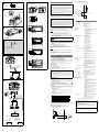
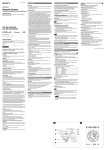
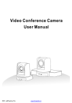
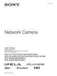
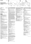
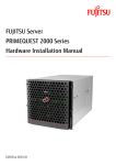
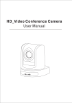
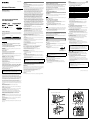
4-199-272-17(1) Network Camera Installation Manual Before operating the unit, please read this manual thoroughly and retain it for future reference. SNC-CH115/CH120/CH220 SNC-EB520/ZB550 2010 Sony Corporation Printed in China Owner’s Record The model and serial numbers are located on the top. Record these numbers in the spaces provided below. Refer to these numbers whenever you call upon your Sony dealer regarding this product. Model No. Serial No. Overview This Installation Manual gives instructions for multiple types of Network Cameras: SNC-CH115/CH120/CH220 are PoE-type HD models, SNC-EB520 is a PoE-type SD model, and SNC-ZB550 is an HD model IPELA HYBRID camera. WARNING To reduce a risk of fire or electric shock, do not expose this product to rain or moisture. To avoid electrical shock, do not open the cabinet. Refer servicing to qualified personnel only. WARNING This installation should be made by a qualified service person and should conform to all local codes. Power Supply Caution for U.S.A. and Canada (SNC-ZB550) The SNC-ZB550 operates on 24 V AC or 12 V DC. The SNC-ZB550 automatically detects the power. In the USA, this product shall be powered by a UL listed Class 2 Power Supply Only. In Canada, this product shall be powered by a CSA Certified Class 2 Power Supply Only. Caution for other countries (SNC-ZB550) The SNC-ZB550 operates on 24 V AC or 12 V DC. The SNC-ZB550 automatically detects the power. Use a power supply rated 24 V AC or 12 V DC which meets the requirements for SELV (Safety Extra Low Voltage) and complies with Limited Power Source according to IEC 60950-1. CAUTION for LAN port For safety reason, do not connect the LAN port to any network devices that might have excessive voltage. CAUTION for LAN port (SNC-CH115/CH120/CH220/EB520) The LAN port of this unit is to be connected only to the devices whose power feeding meets the requirements for SELV (Safety Extra Low Voltage) and complies with Limited Power Source according to IEC 60950-1. Use IEEE802.3af standard compliant devices. For customers in the U.S.A. This device complies with Part 15 of the FCC Rules. Operation is subject to the following two conditions: (1) This device may not cause harmful interference, and (2) this device must accept any interference received, including interference that may cause undesired operation. NOTE: This equipment has been tested and found to comply with the limits for a Class A digital device, pursuant to part 15 of the FCC Rules. These limits are designed to provide reasonable protection against harmful interference when the equipment is operated in a commercial environment. This equipment generates, uses, and can radiate radio frequency energy and, if not installed and used in accordance with the instruction manual, may cause harmful interference to radio communications. Operation of this equipment in a residential area is likely to cause harmful interference in which case the user will be required to correct the interference at his own expense. Notes on Use About the Supplied Manuals Before Use Installation Manual (this document) If you find condensation when you open the package, turn on the power after the condensation disappears. Remove the static electricity before operation or when touching the camera. This Installation Manual describes the names and functions of parts and controls of the Network Camera, gives connection examples and explains how to set up the camera. Be sure to read the Installation Manual before operating. The pictures of an SNC-CH220 camera are used in the explanatory examples. Data and security You should keep in mind that the images or audio you are monitoring may be protected by privacy and other legal rights, and the responsibility for making sure you are complying with applicable laws is yours alone. Access to the images and audio is protected only by a user name and the password you set up. No further authentication is provided nor should you presume that any other protective filtering is done by the service. Since the service is Internet-based, there is a risk that the image or audio you are monitoring can be viewed or used by a third-party via the network. SONY IS NOT RESPONSIBLE, AND ASSUMES ABSOLUTELY NO LIABILITY TO YOU OR ANYONE ELSE, FOR SERVICE INTERRUPTIONS OR DISCONTINUATIONS OR EVEN SERVICE CANCELLATION. THE SERVICE IS PROVIDED AS-IS, AND SONY DISCLAIMS AND EXCLUDES ALL WARRANTIES, EXPRESS OR IMPLIED, WITH RESPECT TO THE SERVICE INCLUDING, BUT NOT LIMITED TO, ANY OR ALL IMPLIED WARRANTIES OF MERCHANTABILITY, FITNESS FOR A PARTICULAR PURPOSE, OR THAT IT WILL OPERATE ERROR-FREE OR CONTINUOUSLY. Always make a test recording, and verify that it was recorded successfully. SONY WILL NOT BE LIABLE FOR DAMAGES OF ANY KIND INCLUDING, BUT NOT LIMITED TO, COMPENSATION OR REIMBURSEMENT ON ACCOUNT OF FAILURE OF THIS UNIT OR ITS RECORDING MEDIA, EXTERNAL STORAGE SYSTEMS OR ANY OTHER MEDIA OR STORAGE SYSTEMS TO RECORD CONTENT OF ANY TYPE. Always verify that the unit is operating properly before use. SONY WILL NOT BE LIABLE FOR DAMAGES OF ANY KIND INCLUDING, BUT NOT LIMITED TO, COMPENSATION OR REIMBURSEMENT ON ACCOUNT OF THE LOSS OF PRESENT OR PROSPECTIVE PROFITS DUE TO FAILURE OF THIS UNIT, EITHER DURING THE WARRANTY PERIOD OR AFTER EXPIRATION OF THE WARRANTY, OR FOR ANY OTHER REASON WHATSOEVER. If you lose data by using this unit, SONY accepts no responsibility for restoration of the data. Personal information The images taken by the system using this device can identify individuals and thus they fall under “personal information” stipulated in the “Act on the Protection of Personal Information”. Please handle the video data appropriately according to law. Information recorded using this product may also be “personal information”. Upon disposal, transfer, repair, or any other occasion where this product or storage media is passed on to a third party, practice due care in its handling. Operating or storage location Avoid operating or storing the camera in the following locations. Extremely hot or cold places (Operating temperature: –10°C to +50°C [14°F to 122°F]) Exposed to direct sunlight for a long time, or close to heating equipment (e.g., near heaters) Close to sources of strong magnetism Close to sources of powerful electromagnetic radiation, such as radios or TV transmitters Locations subject to strong vibration or shock Humid or dusty locations Locations exposed to rain Locations under the influence of fluorescent light or reflection of a window Under an unsteady light (the image will flicker.) Ventilation To prevent heat buildup, do not block air circulation around the camera. Power supply (SNC-CH115/CH120/CH220/EB520) The power of this model is supplied by network cable. Use the network cable UTP, category-5. Damage to the network cable may result in fire or electric shock. Always turn off the power when carrying. When transporting the camera, repack it as originally packed at the factory or in materials of equal quality. Cleaning Use a blower to remove dust from the lens. Use a soft, dry cloth to clean the external surfaces of the camera. Stubborn stains can be removed using a soft cloth dampened with a small quantity of detergent solution, then wipe dry. Do not use volatile solvents such as alcohol, benzene or thinners as they may damage the surface finishes. Note on laser beams Laser beams may damage image sensors. You are cautioned that the surface of image sensors should not be exposed to laser beam radiation in an environment where a laser beam device is used. Phenomena Specific to Image Sensors SNC-CH115/CH120/CH220/EB520 PinNo. 1 2 3 4 User’s Guide (stored in the CD-ROM) The User’s Guide describes how to set up the camera and how to control the camera via a Web browser. After installing and connecting the camera correctly, operate referring to this User’s Guide. PinNo. 1 2 3 4 The supplied CD-ROM disc includes the User’s Guides for this unit in PDF format. Preparations The Adobe Reader Version 6.0 or higher must be installed on your computer in order to use the guides stored in the CD-ROM disc. Note If Adobe Reader is not installed, it may be downloaded from the following URL: http://www.adobe.com/ Reading the manual in the CD-ROM 1 Insert the CD-ROM in your CD-ROM drive. A cover page appears automatically in your Web browser. If it does not appear automatically in the Web browser, double-click on the index.htm file on the CD-ROM. 2 Select and click on the manual that you want to read. This opens the PDF file of the manual. Clicking an item in the Table of Contents allows you jump to the relevant page. Notes The files may not be displayed properly, depending on the version of Adobe Reader. In this case, install the latest version, which you can download from the URL mentioned in “Preparations” above. If you have lost or damaged the CD-ROM, you can purchase replacement. Contact your Sony service representative. Smartphone viewer This product is equipped with a Smartphone viewer. With Smartphone viewer, you can display an image from a network camera, pan, tilt and zoom that camera, on your smartphone. For more details, see “Smartphone viewer User’s Manual” at the following URL: http://www.sony.net/ipela/snc Location and Function of Part Front Lens A vari-focal lens is mounted as standard equipment. Focus ring Turn this ring toward N (near) to focus on a closer object. Turn it toward F or infinite to focus on a farther object. Zoom ring Turn this ring toward T for telephoto, or toward W for wide-angle. Tripod screw hole Use this screw hole when attaching the camera to a tripod. U1/4”, 20 UNC = 4.5 mm to 7 mm (ISO standard) (with the screws fastened) Caution Use the mounting screw whose length is 4.5 mm (3/16 inch) to 7 mm (9/32 inch) only. Use of other screws may cause improper mounting and damage parts inside the camera. Rating Label This label shows the name of device and its electric rating. Lens connector (4-pin socket) Supplies power and control signals to an auto-iris lens. Lens mount (SNC-CH115 only) Use to mount an appropriate CS-mount lens. Use the C mount adaptor (optional) when you use the C-mount lens. (A vari-focal lens is mounted as the standard equipment for SNC-CH120/ CH220/EB520/ZB550.) The following phenomena that may occur in images are specific to image sensors. They do not indicate a malfunction. White flecks Although the image sensors are produced with high-precision technologies, fine white flecks may be generated on the screen in rare cases, caused by cosmic rays, etc. This is related to the principle of image sensors and is not a malfunction. The white flecks especially tend to be seen in the following cases: - when operating at a high environmental temperature - when you have raised the gain (sensitivity) - when using the slow shutter Signal Alarm output 1– Alarm output 1+ Sensor input– (GND) Sensor input+ SNC-ZB550 Using the CD-ROM Manuals Transportation Rear I/O (Input/Output) port This cable is provided with a sensor input and an alarm output. The wires of the cable control the following signals. Signal Sensor input+ Sensor input– (GND) Alarm output 1+ Alarm output 1– F or details on each function and required settings, see the User’s Guide stored in the supplied CD-ROM. F or the wiring, see “Connecting the I/O cable.” LAN network port (RJ-45) Use the network cable (UTP, category-5) for network communications and PoE* power supply. However, the PoE power supply feature is not available on SNC-ZB550. S ee “Connect to the Network” for connection. (* PoE: The acronym for Power over Ethernet. IEEE 802.3af standard compliant devices.) Easy Focus button Press this button to automatically adjust the focus. To load the default setting, press and hold this button for 4 seconds. Fall-prevention wire rope mounting screw hole When installing the camera to the ceiling or the wall, secure the supplied wire rope to this hole using the supplied screw. NETWORK indicator (green/orange) The indicator lights up or flashes when the camera is connected to the network. The indicator is off when the camera is not connected to the network. When 100BASE-TX is connected, the indicator turns green. When 10BASE-T is connected, the indicator turns orange. The indicator also turns green when SLOC (IP coaxial transfer) is selected. Reset switch To reset the camera to the factory default settings, turn on the power to the camera while holding down this switch with a pointed object. POWER indicator (Green) When the power is supplied to the camera, the camera starts checking the system. If the system is normal, this indicator lights up. NTSC/PAL switch Switching the video output. MONITOR output jack Output the composite video signal from the camera. Monitor out is used when you adjust the angle of view. Be sure to set monitor out to on when you use it. Set it to off and disconnect the video cable when you do not use it. For details on system setting, see the User’s Guide. Notes Do not connect to the video cable until the POWER indicator lights up. Be aware that the system performance may be influenced, if monitor out is set to on. Be sure to set it to off and disconnect the video cable when you do not use it. DC 12 V/ AC 24 V (power input) terminal Connect to a 12 V DC or 24 V AC power supply system. Network connection change switch Use this switch to change between a network connection to a LAN (network) port (RJ-45) and a network connection using a coaxial cable. SLOC (IP coaxial transfer/video output) port Use this port when connecting the unit to a network using a coaxial cable. When using a composite signal, set the network connection change switch to LAN. Also use this port to output composite video signals from this unit. A connection to compatible equipment is necessary when connecting to a network using a coaxial cable. For connection details, refer to the instruction manuals of the equipment on the receiving end. Note The output analog image may not display correctly, depending on the video format and image size settings. The image may not display properly in the horizontal and/or vertical plane. The image may be reduced. (ground) terminal This is a ground terminal for the chassis. (continued on the reverse side) Aliasing When fine patterns, stripes, or lines are shot, they may appear jagged or flicker. You are cautioned that any changes or modifications not expressly approved in this manual could void your authority to operate this equipment. All interface cables used to connect peripherals must be shielded in order to comply with the limits for a digital device pursuant to Subpart B of Part 15 of FCC Rules. For customers in Canada This Class A digital apparatus complies with Canadian ICES-003. Cet appareil numérique de la classe A est conforme à la norme NMB-003 du Canada. For the customers in Europe The manufacturer of this product is Sony Corporation, 1-7-1 Konan, Minatoku, Tokyo, Japan. The Authorized Representative for EMC and product safety is Sony Deutschland GmbH, Hedelfinger Strasse 61, 70327 Stuttgart, Germany. For any service or guarantee matters please refer to the addresses given in separate service or guarantee documents. For the customers in Europe, Australia and New Zealand SNC-CH115/CH120/CH220/EB520 SNC-CH120/CH220/EB520/ZB550 WARNING This is a Class A product. In a domestic environment, this product may cause radio interference in which case the user may be required to take adequate measures. In the case that interference should occur, consult your nearest authorized Sony service facility. This apparatus shall not be used in the residential area. ATTENTION The electromagnetic fields at specific frequencies may influence the picture of the unit. SNC-ZB550 SNC-CH115 Wiring diagram for alarm output Installation CS-mount lens Front (SNC-CH120/CH220/ /ZB550) 5.5 (7/32) or less Front (SNC-CH115) 72 (2 7/₈) 63 (2 1/₂) 62 (2 7/₁₆) 63 (2 1/₂) 62 (2 7/₁₆) Unit: mm (inch) Screw (supplied) Front (SNC-EB520) 63 (2 1/₂) 62 (2 7/₁₆) GND Keep the lens mount cap on the camera when it is not attached the lens. When you install it into a wall or a ceiling, check that the wall or the ceiling is strong enough to hold the weight of the camera including the mounting bracket, and install it without fail. If not, the camera falls down and causes a serious injury. Also, check if the mounting is not loosened at least once a year. Make the checking interval short according to use condition. Performance will depend on the installation environment and the lens itself. For details, contact your authorized Sony dealer. 43 (1 3/4) 145 (5 3/4) 140 (5 5/₈) Attaching the wire rope 55 (2 1/4) When you install the camera on a ceiling or a high position, be sure to attach the supplied wire rope to prevent the camera from falling. Attach the wire rope to the screw hole on the rear of the camera, as in the illustration. 145.6 (5 3/4) Note Take care not to short-circuit the cable with the wire rope when you attach it. 1 Secure the wire rope to the junction box on the ceiling. Use a screw to match the screw hole of your junction box (not supplied). 2 Secure the wire rope to the wire rope mounting screw hole on the rear of the camera using the supplied screw. Side (SNC-CH115) 43 (1 3/4) 145 (5 3/4) 140 (5 5/₈) Note Use the supplied screws to install the unit. Using other screws may cause damage inside the unit. 55 (2 1/4) 42.8 (1 11/16) * mark indicates the approximate focus position. 145.6 (5 3/4) Adjusting the Camera Coverage and Focus 1 Loosen the zoom ring locking screw to adjust the camera shooting 145 (5 3/4) 140 (5 5/₈) 2 3 4 5 Side (SNC-EB520) 43 (1 3/4) coverage. Tighten the locking screw to fix the zoom. Loosen the focus ring locking screw to adjust the focus. Tighten the locking screw to fix the focus. Press the Easy Focus button on the rear to automatically adjust the focus. Note 55 (2 1/4) SNC-CH115/CH120/CH220/EB520 You may not achieve satisfactory focus with the Easy Focus button due to the shooting environment. In this condition, press and hold Easy Focus button for more than 4 seconds to return to the default flange back position. Then, adjust the focus following step 3 and 4. 145.6 (5 3/4) Connection Side (SNC-ZB550) Network cable (straight, not supplied) Connect the LAN connector of the camera to a PoE* supported device (such as a hub) using the network cable (straight, not supplied). The electrical power is supplied through the network cable. For details, refer to the instruction manuals of the PoE supported devices. (* PoE: The acronym for Power over Ethernet. IEEE 802.3af standard compliant devices.) 10BASE-T/ 100BASE-TX SNC-ZB550 55 (2 1/4) 150.5 (6) Unit: mm (inch) Connect to a network using a coaxial cable or LAN. Connecting via a coaxial cable When the network connection change switch is set to SLOC, connect to a network via a coaxial cable. The maximum coaxial cable length is RG-59 300 m. Note PoE supported device (such as a hub) The high-frequency characteristics of coaxial cables may differ, even if the cables are of the same classification. Use a high-quality, high-frequency coaxial cable with this unit. F or details, refer to the instruction manual of the connecting SLOC device. For further details, please consult an authorized Sony dealer. When connecting with a coaxial cable, do not connect a network cable to this unit. Connecting via LAN When the network connection change switch is set to LAN, use a network cable (straight, not supplied) to connect this unit’s LAN port to the network’s router or hub. Connecting to a computer Use a network cable (crossover, not supplied) to connect this unit’s LAN port to the computer’s network connector. SNC-ZB550 Compression Video compression format JPEG/MPEG4/H.264 Maximum frame rate SNC-CH115/CH120/ZB550 H.264: 30 fps (1280 × 720) SNC-CH220 H.264: 30 fps (1920 × 1080) SNC-EB520 H.264: 30 fps (800 × 600) Camera Signal system NTSC color system/PAL color system (switchable) Image device SNC-CH115/CH120/EB520/ZB550 1/3type CMOS (Exmor) Effective picture elements: Approx. 1,390,000 SNC-CH220 1/2.8type CMOS (Exmor) Effective picture elements: Approx. 3,270,000 Synchronization Internal synchronization Minimum illumination SNC-CH120/ZB550 F1.2/AGC 42 dB/50 IRE (IP) Color 0.50 lx Black & White 0.30 lx SNC-CH220 F1.3/AGC 42 dB/50 IRE (IP) Color 0.70 lx Black & White 0.45 lx SNC-EB520 F1.0/AGC 42 dB/50 IRE (IP) Color 0.47 lx Black & White 0.27 lx Lens Focal length Maximum relative aperture View angle Minimum object distance SNC-CH115/CH120/CH220/EB520 43 (1 3/4) Specifications Connect to the Network 145 (5 3/4) 140 (5 5/₈) 52 (2 1/8) Connecting to 12 V DC or 24 V AC source − + LAN Coaxial cable + − Coaxial cable maximum length: RG-59 300 meters Network cable (straight, not supplied) 10BASE-T/ 100BASE-TX Hub Connect the power input cable of the camera to a 12 V DC or 24 V AC source. Use a 12 V DC or 24 V AC source isolated from 100 to 240 V AC. The acceptable voltage ranges for each are as follows. 12 V DC: 10.8 V to 13.2 V 24 V AC: 21.6 V to 26.4 V - In the USA, The product shall be powered by a UL Listed Class 2 Power Supply Only. - In Canada, The product shall be powered by a CSA certified Class 2 Power Supply Only. Use UL cable (VW-1 style 10368) for these connections. recommended cable DC12 V: CABLE(AWG) #26 #24 #22 8 12 21 CABLE(AWG) #26 #24 #22 Max. length(m) 32 50 85 Max. length(m) AC24 V: LAN (PoE)* 10BASE-T/100BASE-TX, auto negotiation (RJ-45) * The PoE power supply feature is not available on SNC-ZB550. I/O port Sensor input: × 1, make contact, break contact Alarm output: × 1, 24 V AC/DC, 1 A (mechanical relay outputs electrically isolated from the camera) MONITOR out (SNC-CH115/CH120/CH220/EB520) Pin jack 1.0 Vp-p, 75 ohms, unbalanced, sync negative SLOC port (SNC-ZB550) 1.0 Vp-p, 75 ohms, unbalanced, sync negative (during video output) Others Power Power consumption Operating temperature Storage temperature Operating humidity Storage humidity Dimensions (w/h/d) Connecting the I/O Cable Connect the wires of the I/O cable as follows: Wiring diagram for sensor input Mechanical switch/open collector output device Camera inside Outside 3.3 V Supplied accessories Design and specifications are subject to change without notice. 47 kΩ 30 kΩ LAN port (RJ-45) Network cable 10BASE-T/ 100BASE-TX Network device In case using this device over an extended period of time, please have it inspected periodically for safe use. It may appear flawless, but the components may have deteriorated over time, which may cause a malfunction or accident. For details, please consult the store of purchase or an authorized Sony dealer. sloc™ is a trademark owned by the Intersil Corporation family of companies. SLOC-compatible device Video monitor (etc.) Mass Adobe and Acrobat Reader are trademarks of Adobe Systems Incorporated in the United States and/or other countries. SLOC connector Coaxial cable SNC-CH115/CH120/CH220/EB520: IEEE802.3af compliant (PoE system) SNC-ZB550: DC 12V/AC 24V SNC-CH115/CH120/CH220/EB520: 5.0 W max. SNC-ZB550: 6.0 W max. Start temperature: 0°C to 50°C (32°F to 122°F) Working temperature: –10°C to +50°C (14°F to 122°F) –20°C to +60°C (–4°F to +140°F) 20% to 80% 20% to 95% SNC-CH115 72 mm × 63 mm × 145 mm (2 7/8 inches × 2 1/2 inches × 5 ³/₄ inches) not including the projecting parts and lens SNC-CH120/ZB550 72 mm × 63 mm × 197 mm (2 7/8 inches × 2 1/2 inches × 7 7/8 inches) with lens not including the projecting parts SNC-CH220 72 mm × 63 mm × 197.3 mm (2 7/8 inches × 2 1/2 inches × 7 7/8 inches) with lens not including the projecting parts SNC-EB520 72 mm × 63 mm × 187.8 mm (2 7/8 inches × 2 ½ inches × 7 ½ inches) with lens not including the projection parts SNC-CH115 Approx. 490 g (1 lb 1.3 oz) without lens SNC-CH120/CH220/ZB550 Approx. 550 g (1 lb 3.4 oz) with lens SNC-EB520 Approx. 530 g (1 lb 2.7 oz) with lens CD-ROM (Users Guides, and supplied programs) (1) Wire rope (1) Screw M4 (1) DC 12V/AC 24V connector (1) (SNC-ZB550) Installation Manual (this document) (1) Recommendation of Periodic Inspections Network Video output terminal SNC-CH120/ZB550: 2.8 mm to 8.0 mm SNC-CH220: 2.8 mm to 6.0 mm SNC-EB520: 3.0 mm to 8.0 mm SNC-CH120/ZB550: F1.2 to F1.9 SNC-CH220: F1.3 to F1.9 SNC-EB520: F1.0 to F1.65 SNC-CH120/ZB550: 1280 × 1024 Vertical: 76.2° to 27.2° Horizontal: 96.5° to 33.9° SNC-CH220: 1920 × 1440 Vertical: 74.2° to 35.2° Horizontal: 101.2° to 47.0° SNC-EB520: 800 × 600 Vertical: 70.2° to 27.7° Horizontal: 89.2° to 34.6° SNC-CH115/CH120/CH220/ZB550: 300 mm SNC-EB520: 200 mm Interface SNC-ZB550 DC 12V/AC 24V Circuit example Alarm Output − Caution SNC-CH120 : 52 (2 1/₈) SNC-CH220 : 52.3 (2 1/₈) The number indicates the focus position. Magnet relay AC 24 V DC 24 V 1 A or less The lens must be a CS-mount type and the protrusion behind the mounting surface must be 5.5 mm (7/32 inch) or less. Side (SNC-CH120/CH220) When Easy Focus button is pressed Alarm Output + Suitable lens Wire rope (supplied) Outside 5V Caution If you attach the camera in a high location such as wall or ceiling, etc., entrust the installation to an experienced contractor or installer. If you install the camera in a high location, ensure that the ceiling is strong enough to withstand the weight of the camera plus mounting brackets and screws, and then install the camera securely. If the ceiling is not strong enough, the camera may fall and cause serious injury. To prevent the camera from falling, make sure to attach the supplied wire rope. If you attach the camera to the ceiling, check periodically, at least once a year, to ensure that the connection has not loosened. If conditions warrant, make this periodic check more frequently. 72 (2 7/₈) 72 (2 7/₈) Camera inside Sensor input − (GND) 10 kΩ GND Sensor input + GND Mechanical switch or Open collector output device