1
generation ATR technology that provided
frame rates factors faster than previous
sensors. The speed of this new ATR was
combined with a high-speed quadruple
detection angle reading system and all
new proprietary Piezo direct drives that
allowed high speed tracking applications
to become a reality. The TDRA6000 was
the first metrology based total station to
have
the
speed
and
dynamics
approaching a traditional laser tracker,
but its accuracy was still factors less
than required.
The Alidade
The lower stand assembly (alidade)
includes everything except the telescope.
The design and development of this
structure exemplifies the depth of Leica
Geosystems and Hexagon Metrology.
Components of this alidade are shared
between the TS30 Surveying platform,
the TPS6000 Metrology platform and now
the AT401 laser tracker. All of these
sensors share the same 0.5 arc second
angular encoders, the same precision
level to gravity sensor and the same
advanced Piezo drive technology.
Although the individual design criteria
are different, all of these sensors share
the same need for an extremely sturdy
alidade. In order to guarantee 0.5”
accuracy
under
very
demanding
conditions
(changing
temperatures,
wind, rain, etc…) a new design and
manufacturing process was required
compared to standard total stations.
The Alidade for these sensors was
designed with all of these parameters in
mind and utilizes a low pressure casting
technology. This “gravity fed” casting
process is slower and more costly than
standard die-casting technology that is
common in modern total stations, but is
the only way to achieve the temperature
stability and stiffness that is required by
these ultra high accuracy sensors.
The Angle Measurement System
The angle measurement system is a very
significant component for the products
based on this common alidade. The
angle encoders must guarantee highly
precise
and
accurate
angle
measurements, and must do so even
under the high speed of the Piezo direct
drives. The quadruple reading angle
measurement system consists mainly of
a coded glass circle and four encoders.
Each encoder has an LED light source,
mirrors for reflecting the emitted light,
and a digital line sensor. The coded glass
circle is based on radially aligned lines
and is absolute and continuous. No
initialization of the angle sensor is
required prior to being able to measure.
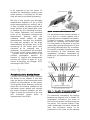
Figure 2 shows a 3D-illustration of an
exemplary single encoder and the coded
glass circle of the angle measurement
system.
Figure 2 – Single encoder of the angle measurement system
with a light source (LED) and a line sensor.
For the angle measurements, a light
emitted by the LED is projected through
the coded glass circle and onto the line
sensor. In order for the image from the
line sensor to be transformed into
relative angle information, it must first be
decoded. A first coarse angle is detected
with an accuracy of about 0.3 gon based
on the individual coded lines. The precise
angle measurement is calculated from
the position of the coded lines’ centroid
with algorithms developed by Leica
Geosystems.
For
a
position
determination, at least 10 code lines have