1
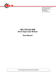
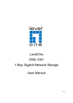
Helm Instrument Company, Inc.
361 West Dussel Drive
Maumee, Ohio 43537 USA
419/ 893-4356
Fax: 419/ 893-1371
www.helminstrument.com
COMPASS PLM-4
USER MANUAL
Revised Feb 5 , 2008
Force Measurement and Control Solutions
I.
OVERVIEW
The Helm model “Compass PLM-4” is a portable four channel strain
gage signal conditioner, that displays peak force and waveforms on a
handheld “Palm” unit through infra-red transceiver technology.
A. Features:
1. The front of the unit contains the following:
a. On-off switch
b. Battery status indicator L.E.D.’s
c. Power status L.E.D.’s
d. Infra-red transmit / receive window.
2. The rear of the unit contains the:
a. External charging jack
b. Four 7-pin amphenol connectors for sensor inputs
c. Chassis ground post
B. Connection of Strain Gages:
1. Looking at the rear of the unit, from left to right, the
sensor inputs are: Ch.1, Ch.2, Ch.3 & Ch.4.
2. The wiring code for each channel is: Pin-a (+)gage,
Pin-b (-)gage, Pin-c(+)signal, Pin-d(-) signal, Pin-g
shield.
C. Charging the Unit
1. Plug-in the supplied 9vdc AC adapter to the charging
jack on the rear of the enclosure.
2. Approximate charging time is (4) hours from the “Low”
state.
3. During charging, the “Battery OK” and the “Battery
CHG” L.E.D.’s will come on.
4. When the unit is full charged, the “Battery CHG” L.E.D.
will go out.
5. If the “Low Bat” L.E.D. comes on during operation, stop
use immediately and charge the unit.
D. Location of Palm Unit
1. Palm unit must face the front panel of Compass PLM4 within 3
feet of distance in same surface.
2. The best operating location for your palm unit is a foot away
from the front panel of Compass PLM4 in same surface where
Compass PLM4 is positioned and pointing each other.
II.
UNIT SET-UP PROCEDURE WITH LOAD CELLS
(Note: Palm unit must have Helm software loaded.)
Starting Compass PLM4 software
1. Start Palm Unit.
2. Click PLM4 icon from Palm windows.
3. If you do not see PLM4 Icon, set application filter to ALL
A. Entering "Scale" value:
1. From the main screen, scroll down to and select the "PLM-4”
icon.
2. Select “Compass PLM4”, “Options", then “PLM-4 Setup”.
3. Select “Edit” to allow set-up.
4. Select Ch.1, then “Scale Value” field. Now touch the “123” area
on the front of the Palm Unit to allow access to the data entry
screen.
5. Enter the capacity of the load cell connected to that channel.
EXAMPLE: For a ten ton load cell, to read 10.0 instead of just
10, enter “100” for scale, then select “0.1” for DEC.
6. Click “Save” to store what you have changed so far and click
“Edit” again to continue making other changes or just continue
to next parameters and click save when all changes have been
made at the end.
B. Entering a "mV/V" value:
6. Touch the “mV/V” field in the same line. Now, touch the
“123” portion on the front of the Palm unit again to gain
access to the data entry screen. Enter the "mV/V"
value stamped on the tag of the load cell connected to
that channel. EXAMPLE: “2.036” mV/V - as you enter
this value, you will need to enter the decimal point as it
is shown on the tag. Then touch “Done”. Now select
"Save", then "Edit".
C. Zero Balancing the Channel:
7. Select Zero “On” to balance Ch. 1 to zero. Wait for the
value in the window to go to zero. When at zero, touch
“Off”. Then select “Save” again.
8. The above procedure (Steps 3 thru 7) must be
repeated for each channel that has a load cell
connected to it. Start with Ch. 2 now, by selecting
"Edit” again.
9. Finish the set-up for all channels by selecting “Return”.
Touch “Reset”. Unit is now in peak mode and ready to
register a dynamic reading.
D. Peak Look Window, Initial Setting:
10. Select "CompassPLM4", "Options", then "PLM-4 Set-up".
Touch "Edit", then Select "PKLW" field, then touch the
"123" area on the front of the Palm Unit. Type "100",
then touch "Done", and "Save".
11. Now, select "Return", and "Reset".
III.
VIEWING AND STORING FORCE SIGNATURES
A. Viewing and Saving Current Tonnage
Signature
1. Touching any tonnage reading while in peak
mode will display the force signature for that
channel.
2. Selecting the “Total” window
will display a composite view
of all four waveforms, overlaid
on that screen.
3. To store the force signature,
click Save button.
*Note: If you save new captured tonnage data from the Main screen without
viewing the force signature first, only the peak data will get stored. To
insure the storage of captured tonnage signature data, always click save
button from any Signature Screen.
B. Viewing Stored Tonnage and Signature Data:
1. Select "Compass PLM4" on top of the main
screen, then click "View" and “Stored
Tonnage Data”.
2. Each line of stored data shows the date,
time, and channel number you will be viewing.
3. Select a line, then touch “Details".
4. Click “Details” to go to Detial View
screen of selected record that was
previously stored. You can add or edit
any “Note” section to each record here.
Make sure to hit “Save” button after you
made any change to the Note area.
5. Select any channel or total display to view
stored signature the record.
COMPASS PLM-4 SOFTWARE SCREEN REFERENCE
Main Screen
Click here to bring
down menu to access
more options
Last date & time when the
tonnage data has been
recorded from PLM4
Last Peak
Tonnage reading
Save current tonnage
reading to memory. If
this button is used before
viewing signature, only
tonnage value will get
stored without signature
data.
Current Operating
Mode Indication
Tonnage Display shows
Reverse Load for
duration of 5 sec.
Then, returns back to
Peak Load.
Operating Mode select
buttons
Clears tonnage reading
to Zero in PEAK mode.
2. Signature Display
From Main screen, click on one of the load display to access signature screen
This screen shows the current captured load signature of the selected channel.
Click Save button to save current signature data to palm memory which you can retrieve
and view later from View Stored Load Data screen.
3. Signature Overlay Display
From Main screen, click on the total load display to access “Signature Overlay” screen.
Legend
Channel 1 (Red)
Channel 2 (Green)
Channel 3 (Yellow)
Channel 4 (Blue)
This screen shows all 4 channels of load signatures on one screen. Please refer to the
color legend for channel designation.
4. PLM Setup Screen
When you connect new load cells to the Compass
PLM4, you need to set up the Compass PLM4
with proper parameters. To do this, from top
menu, go to Options->PLM Setup.
PLM Setup screen allows you to enter scale values, mV/V values, Look Window time,
and zero balance for the each load cell connected. Before you make any changes to the
settings, make sure to enable the “Edit” mode by clicking on “Edit” button.
Enter Max Capacity
of the load cell for
the connected
channel
Click Off button to
clear the scale value
to 0. This can be
use to turn off the
channel(s) that load
cell is not connected
Select a channel
number you wish to
zero the balance.
Select decimal point
to be shown on the
load reading.
1. Click this button
to enable Edit mode
to make any
changes on settings.
When edit is done,
Click this
button(Save) to save
the new settings to
PLM4 memory
Turn on Zero to tier the zero balance for
each channel selected from “CH Select”
Make sure to turn off before select different
channel. Once Zero balance for all channel
is done, Click Edit and Save to store the
zero reference to PLM4 EPROM.
IV.
TROUBLE SHOOTING
A. Palm unit will not respond:
Click Recvr (Recovery) button from main CompassPLM4 screen.
If there is still no communication from the Compass PLM-4 unit,
make sure that power is on at the Compass PLM-4 unit and the I/R
window has a clear path to the Palm unit.
B. A given channel will not balance to zero:
Sensor is disconnected - connect sensor or:
Sensor is preloaded - remove preload.
C. Waveform is not visible:
Go to "PLM-Setup" screen and enter a larger Peak Look
Window (PKLW) value. EXAMPLE: Current value is
100 ms - try 1000 ms (1 second) or larger, if needed.