1
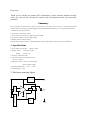
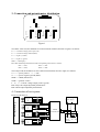
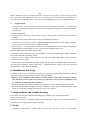
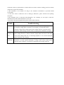
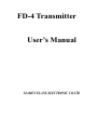
FD-4 Transmitter
User’s Manual
XIAMEN ELANE ELECTRONIC CO.LTD
Dear users,
Thank you for buying our product (FD-4 transmitter), please read this manual carefully
before use, and you are welcomed to contact with our technician when you meet some
problems.
Summary
FD-4 is designed to match with our strain type load cells, can be widely used in the non - electrical measurement
situations that use strain type load cells. High precision, stable performance and easy use is our product characteristics:
1 Suitable for strain type load cells;
2 Can connect 1-4 load cells directly;
3 Can protect reverse connect of voltage, and protect output;
4 Two options: Electrical current/voltage output;
5 Multiple options of output capacity.
Please indicate the type (current or voltage transmitter) and the output capacity when you order our transmitters.
1. Specifications
1) Power supply: DC15V/24V
2) Output: current
150mA MAX
4-20mA or 0-10mA
Voltage
0-5V or 1-5V
3) Accuracy: Excelled 0.1%FS
4) The total sensitivity of connecting sensors:
1.1mV/V~2.2mV/V
5) Resistance of load: ≤350Ω (current output)
≥250Ω(voltage output)
6) Operating temperature: -20℃~ +85℃
7) Protection class:
IP65
2. Electronic principle figure
Stable
voltage switch
LOAD CELL
#
1 -4
Opera
#
Filter
V+
V/ I
I/Vout+
te
Adjust zero circuit
Voltage
switch
GND
3. Connection and potentiometer distribution
V+ V- Shie Gnd Io/Vo+
RP6
RP5
RP4
S+
SEE+
SHIE
SXS4
E-
RP3
S+
SEE+
SHIE
RP2
S+
SEE+
SHIE
XS3
XS2
RP1
S+
SEE+
SHIE
XS1
Figure 1
XS1-XS4: sensor end, the definition of each connection terminal (from left to right) is as follows:
E+-------excitation voltage positive pole (red)
E- -------excitation voltage cathode (black)
S- -------signal (-) (white)
S+-------signal (+) (green)
SHIE------shield (gray)
RP1~RP4: Balanced potentiometers and the corresponding load cells are as follows:
RP1-------XS1,
RP3-------XS3
RP2-------XS2,
RP4-------XS4
XS5: output end, the definition of each connection terminal (from left to right) is as follows:
V+-------- power positive (+)(red)
V- ---------power negative/ground (black)
SHIE------shield (naked wire)
GND------ground(white)
I。/V。+-----Current/ voltage output positive (green)
RP5: fully scale output adjustable potentiometer
RP6: initial output adjustable potentiometer
4. Connection of test system
Please see the figure 2.
DColtage
LOAD CELL
Power supply
4#
Physical factors
(
)
-(
)
+
LOAD CELL
3#
TRANSMITTER
LOAD CELL
2#
V-
FD-4
Shie
V+
Gnd
-
RL
Io/Vo+
+
(RL:load resistance
LOAD CELL
1#
Indicator and
equipment
other
Fig. 2
Notice: When you order our voltage transmitter with the relevant sensor, you do not need to adjust
again, because we have adjusted it before leave our factory, please connect the test system directly; if
you only buy the transmitter, please connect the wire and adjustment as per the operating instrument.
5. Adjustment
Open the cover, you can find the potentiometer and the terminal (see figure 1). Connect with
transducers, and put the transmitter into the system of measurement (figure 2). Then link the power
and turn it on.
A: balanced adjustment
1 Load each sensor separately, and record the current/ voltage output of each sensor under the load
condition.
2 Count the average output, and use these data as a benchmark when adjust.
3 Load on each sensor again separately, adjust the balanced potentiometer (RP1~RP2), and make
sure the output of sensor is the same with the benchmark.
4 Repeat the step 1 ~ 3 mentioned above (there are some influence between each other when adjust the
potentiometer), until the output of sensor is the same the benchmark when load.
B Output adjustment (after balanced adjustment)
1 When the system is unloaded, adjust the preliminary output and the potentiometer (RP6), and make
the output reached the preliminary output.
2 When the system is fully loaded, adjust the full output of potentiometer (RP5), make the output
reached the full scale output.
3 If the output do not reached the preliminary output after the system is unloaded (adjust full scale load
may affect the preliminary output), repeat step 1 ~2 mentioned above, until the full scale output and
the preliminary output reach the standard.
6. Installations and Usage
1 Connect strictly as per the definitions, especially pay attention to distinguishing transducers end and
output end, wrong connection will result in no output and damage.
2 If there are any redundant cable conductors which connect to the sensor, you must tie up the
wire and make sure the cable is not connect to each other, no short circuit (especially E+ and
E-), otherwise it will damage the transmitter.
3 Except the adjustable electronic potentiometer, please do not change other organ of the transmitter.
4 The transmitter should be installed in the place without any surge impact. Installation must be stable
and try to avoid bump, shouldn’t have strong corrosive gas around it.
7. Judge troubles and trouble-shooting
Please make sure the right connection and debugging according to the operating instruction.
Please reference graph 1.
If the users judge there is something wrong with the transmitter’s organ or the circuit board has been
damaged, please send the product back for repairing.
8. Notice
1 Generally, the transmitter is matched with our strain type load cells, so there is a fixed inner
connection, and every potentiometer is sealed. If the user wants to connect or debug, please let us know,
usually do not open the transmitter.
2 The transmitter is not suitable for using in the insulation environment or powerful humid
environment.
3 If the users want to connect the wire or debug by themselves, please reference the operating
instruction.
4 The transmitter that is connected and debugged by our company, we can repair it when the
transmitter has troubles under normal use in one year.
5 If you have some special requirement, please contact with us directly.
Trouble
Trouble-shooting
NO Output
1) Check power supply; 2) Check voltage of E+ and E-, if power supply is good but
no excitation voltage please send back to our company; 3) If the load cell has
excitation voltage but no output signal, please change load cell; 4) For the current
transmitter, audion damage will also cause no output, please send back to company.
No
Reaction on
load
1) Check voltage of E+ and E- or S+ and S-, if load cell has excitation voltage,
please change load cell; 2) Check if sensitive output under real load is in the range,
if not, please change load cell; 3) Calculating amplifier or V/I or tracker damaged,
please send back to the company.
Output
Abnormity
1) Check if the load cell parameter changed, if changed, please readjust the
transmitter; 2) Leach capacitor damaged or voltage switch circuit trouble, please
send back to the company; 3) If load cell is abnormal, please change load cell.