1
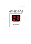
CONTENTS
I. JOINING APPLIANCES / TABLES .................................................................................................... 2
II. DATAPLATE and TECHNICAL DATA ............................................................................................... 14
III. GENERAL INSTRUCTIONS .............................................................................................................. 15
IV. THE ENVIRONMENT ......................................................................................................................... 16
1. PACKING ............................................................................................................................................ 16
2. USE
............................................................................................................................................. 16
3. CLEANING ......................................................................................................................................... 16
4. DISPOSAL ......................................................................................................................................... 16
5. RADIO INTERFERENCE ................................................................................................................... 16
V. INSTALLATION ................................................................................................................................. 16
1. GUIDELINES ...................................................................................................................................... 16
2. UNPACKING ...................................................................................................................................... 16
3. POSITIONING .................................................................................................................................... 16
4. CONNECTIONS ................................................................................................................................. 17
VI. INSTRUCTIONS FOR THE USER ..................................................................................................... 17
1. COOKTOP USE (N9E/N7E) ............................................................................................................... 17
2. ELECTRIC OVEN .............................................................................................................................. 19
VII. CLEANING ....................................................................................................................................... 20
1. EXTERNAL PARTS ............................................................................................................................ 20
2. OTHER SURFACES ........................................................................................................................... 20
3. FILTERS ............................................................................................................................................. 20
4. IDLEPERIODS ................................................................................................................................... 20
5. INTERNAL PARTS ............................................................................................................................. 20
VIII. MAINTENANCE .............................................................................................................................. 21
1. WARNINGS ........................................................................................................................................ 21
2. TABLE OF WARNINGS ...................................................................................................................... 21
3 INEFFICIENCIES DETECTED DURING COOKING .......................................................................... 21
13
II. DATAPLATE and TECHNICAL DATA
ATTENTION
This instruction manual contains information relevant to various appliances. See the dataplate located under the
control panel to identify the appliance (see fig. above).
T ABLE A - Infra re d a pplia n ce s te ch nica l da ta
N 9E
M OD EL S
+9IRED2000
400m m
TEC HNICAL DA TA
Po w e r s up p ly vo lt ag e
N 7E
+9 IREH400 0
800m m
+9IREH400N
800m m
+7IRED2000
400m m
+7IREH4000
8 00m m
+7IREH40E0
800m m
+7 IRED20 0N
400m m
+7IREH400N
800m m
V
40 0
400
230
400
400
23 0
230
230
Fr e q u e n cy
Hz
50/60
50 /60
50/60
50/60
5 0/60
50/60
50 /60
50/60
Ph as e s
No .
3+N
3
3+N
3+N
Ho tp lat e s
No .
2
4
4
2
4
4
2
4
C oo k t o p h o t plate s
kW
6,8
13 ,6
13,6
4,4
8,8
8,8
4 ,4
8,8
Ove n
kW
-
3
3
3
-
-
-
-
4,95
-
-
kW
6,8
13 ,6
13,6
4,4
8,8
13,75
4 ,4
8,8
mm2
1,5
2 ,5
6
1,5
2,5
6
1 ,5
2,5
M ax. t o t al p ow e r
Po w e r s up p ly cab le s e ct ion
3+N
TABLE A - Induction appliances technical data
N9E
MODELS
TECHNICAL DATA
N7E
+9INED2000
400mm
+9INEH4000
800mm
+9INED200N
800mm
+9INEH400N
800m m
+9INEDW00P
400m m
+7INED2000
400m m
+7INEH4000
800m m
+7INEH2F00
800mm
+7INED200N
800mm
+7INEH400N
800m m
+7INED200P
400m m
+7INEH400P
800m m
V
400
400
230
230
400
400
800
400
230
230
400
400
400
No.
3+N
3+N
3
3
3+N
3+N
3+N
3+N
3
3
3+N
3+N
3+N
Fre quency
Hz
50/60
50/60
50/60
50/60
50/60
50/60
50/60
50/60
50/60
50/60
50/60
50/60
50/60
Hotplates
No.
2
4
2
4
1
2
4
2
2
4
2
4
1
Max. total pow e r
kW
10
20
10
20
5
7
14
10
7
14
10
20
5
m m2
2,5
4
4
10
2,5
2,5
4
4
4
10
2,5
4
2,5
Pow e r s upply voltage
Phases
Pow e r s upply cable section
14
+7INEDW00P
400m m
III. GENERAL INSTRUCTIONS
• Read the instruction manual carefully before using the appliance.
•
Keep the instruction manual for future reference..
• RISK OF FIRE - Keep the area around the appliance free and clear of combustibles. Do not keep
flammable materials in the vicinity of the appliance.
• Install the appliance in a well-ventilated place to avoid the creation of dangerous mixtures of unburnt
gases in the room.
• Air recirculation must take into account the air necessary for combustion 2 m³/h/kW of gas power, as
well as the well-being of persons working in the kitchen.
• Inadequate ventilation causes asphyxia. Do not obstruct the ventilation system in the place where this appliance is
installed. Do not obstruct the vents or ducts of this or other appliances.
sos
• Place emergency telephone numbers in a visible position.
•
Installation, maintenance and conversion to another type of gas must only be carried out by qualified personnel authorised
by the manufacturer. For assistance, contact an authorised technical centre. Demand original replacements parts.
•
This appliance is designed for cooking food. It is intended for industrial use. Any use different from that indicated is
improper.
•
This appliance is not intended for use by people (including children) with limited physical, sensory or mental abilities
or without experience and knowledge of it, unless they are supervised or instructed in its use by a person responsible
for their safety.
•
Personnel using the appliance must be trained. Do not leave the appliance unattended when in use.
•
Turn the appliance off in case of a fault or poor operation.
• Do not use products (even if diluted) containing chlorine (sodium hypochlorite, hydrochloric or muriatic
acid, etc.) to clean the appliance or the floor under it. Do not use metal implements to clean steel parts
(wire brushes or Scotch Brite type scouring pads).
• Do not allow oil or grease to come into contact with plastic parts.
• Do not allow dirt, fat, food or other residuals to form deposits on the appliance.
•
Do not clean the appliance with direct jets of water.
•
The symbol
given on the product indicates that it should not be considered domestic waste, but must be
correctly disposed of in order to prevent any negative consequences for the environment and the health of people.
For further information regarding the recycling of this product, contact the product agent or local dealer, the after-sales
service or the local body responsible for waste disposal.
L
Failure to observe the above can compromise the safety of the appliance. Failure to observe the
above invalidates the warranty.
15
IV. THE ENVIRONMENT
V. INSTALLATION
1. PACKING
1. GUIDELINES
The packing materials are environmentally friendly
and can be stored without risk or burned in an
appropriate waste incineration plant.
Recyclable plastic components are marked with:
PE
PP
Polyethylene: outer wrapping, instruction booklet
bag, gas nozzle bag.
Polypropylene: roof packing panels, straps.
Polystyrene foam: corner protectors.
PS
2. USE
Our appliances offer high performance and efficiency. To reduce electricity, water or gas consumption, do not use the
appliance empty or in conditions that compromise optimum
efficiency (e.g. with doors or lids open, etc.); the appliance
must be used in a well-ventilated place, to avoid the creation
of dangerous mixtures of unburnt gases in the room.
When possible, preheat only before use.
3. CLEANING
In order to reduce the emission of pollutants into the
environment, clean the appliance (externally and when
necessary internally) with products that are more than 90%
biodegradable (for further information refer to section V
“CLEANING”).
4. DISPOSAL
Do not disperse in the environment. Our
appliances are manufactured using more
than 90% (in weight) recyclable metals
(stainless steel, iron, aluminium, galvanised
sheet, copper, etc.).
Make the appliance unusable by removing
the power cable and any compartment or cavity closing
devices (when present) in order to avoid the risk of someone
becoming trapped inside.
5. RADIO INTERFERENCE
This appliance conforms to Directive EEC 89/336 relevant
to the suppression of radio interference.
16
Important!
The technological systems and equipment must be installed
by qualified personnel authorized to issue the certificates
of conformity and compliance with current regulations.
Important!
The equipment is marked with the induction generator
frequency or frequency range in kHz.
Caution: Magnetic fields!
The symbol
on the bottom panel of the equipment
indicates the presence of magnetic fields generated by the
same (frequency range: 10-100 kHz).
Important!
In case of accidental breaking of the vitroceramic surface,
immediately unplug the equipment.
2. UNPACKING
Remove the packing. Carefully remove the protective film from
metal surfaces. Remove any traces of glue using a suitable solvent.
IMPORTANT! Immediately check for any damage caused
during transport.
• Inspect the packaging materials before and after unloading.
• The forwarder is responsible for the goods during
transport and delivery.
• Make a complaint to the forwarder in the event of apparent
or hidden damage. Specify any damage or shortages on
the dispatch note.
• The driver must sign the dispatch note: the forwarder
can reject the claim if the dispatch note is not signed
(the forwarder can provide the necessary form)
• For hidden damage or shortages becoming apparent only
after unpacking, request the forwarder for inspection of
the goods within and not later than 15 days from delivery.
• Keep all the documentation contained in the packing.
3. POSITIONING
3.1. GENERAL INFORMATION
• Handle the equipment with care in order to avoid damage or
danger to persons. Use a pallet for handling and positioning.
• The installation diagram given in this instruction manual gives
the appliance dimensions and the position of connections
(gas, electricity, water). Check that they are available and ready
for making all the necessary connections.
• The appliance can be installed separately or combined
with other appliances of the same range.
• The appliances are not designed for built-in installation. Leave
at least 10 cm between the appliance and side or rear noncombustible walls. Leave at least 25 cm between the appliance
and side or rear walls made from combustible materials.
• Suitably insulate surfaces that are at distances less than
those recommended.
• Maintain an adequate distance between the appliance
and any combustible walls. Do not store or use flammable
materials and liquids near the appliance.
• Leave an adequate space between the appliance and any
side walls in order to enable subsequent servicing or
maintenance operations.
• Check and if necessary level the appliance after
positioning. Incorrect levelling of the appliance can affect
combustion and cause malfunctioning.
3.2. FLOOR FIXING
To avoid accidental tipping of built-in half-module appliances
installed separately, fix them to the floor carefully following the
instructions enclosed with the corresponding accessory (F206136).
3.3. COMBINING APPLIANCES
•
(Fig. 1A) Undo the 4 fixing screws and remove the control
panels of the appliances.
• (Fig. 1B) Remove the fixing screw nearest the control
panel, from each side to be joined.
• (Fig. 1D) Bring the appliances together and level them
by turning the feet until the tops match.
• (Fig. 1F) From the rear of the appliances, insert the coupling
plate supplied in the side housings on the back panels.
Secure the plate with two flathead M5 screws provided.
• (Fig. C) Turn one of the two plates inside the appliances 180º.
• (Fig. E) From inside the control panel of the same
appliance, join them at the front side, screwing one TE
M5x40 screw (supplied) on the opposite insert.
NB: For appliances installed individually or for appliances at
the front of an installation (where the joining plate is not used),
insert the plug “T” (Fig1G) supplied, in the side housings on
the back. Tighten the plug with the self-tapping screw supplied.
3.4 ASSEMBLY AND JOINING OF COUNTER TOP
APPLIANCESONBASE,OVEN,BRIDGE,CANTILEVER
Follow the instructions supplied with the optional product chosen.
IMPORTANT! INSTALLATION LIMITS Induction appliances
cannot be installed on the hygienic base or hot cupboard, as
this would make cooling of the components impossible, with
consequent malfunctioning. In case of installation on a counter,
position a baffle (A) to separate the cooling air inflow (IN) and
outflow (OUT) . The baffle must close the space between the
bottom and the counter.
IMPORTANT! OPERATING LIMITS. Induction appliances:
to guarantee continuous operation at maximum power, the
room temperature must be below 40 °C.
IMPORTANT! The manufacturer declines any responsibility
if the safety regulations are not respected.
4.1.2. POWER SUPPLY CABLE
Unless otherwise specified, our appliances do not come equipped with a
powersupplycable.Theinstallermustuseaflexiblecablehavingcharacteristics
at least equivalent to H05RN-F rubber-insulated type cables. Protect the
cable section outside the appliance with a metal or rigid plastic pipe.
4.1.3. CIRCUIT BREAKER
Install a circuit breaker ahead of the appliance. Contact
opening distance and maximum leakage current must comply
with current regulations.
4.2.EQUIPOTENTIAL NODE AND EARTH
CONNECTION
Check the conformity of the electrical system with current
standards and ensure that the prescribed protection and
safety devices are installed. The appliance must be earthed;
it must be included in an equipotential node by means of the
screw located under the appliance frame at the front right.
.
The screw is marked with the symbol
VI USER INSTRUCTIONS
1. COOKTOP USE (N9E/N7E)
1.1. INFRARED MODELS
The 1/2 module cooktops have two 3,4kW. (N9E)/2,2 kW
(N7E). radiating zones. The 1 module cooktops have four
3,4kW. (N9E)/2,2 kW (N7E) radiating zones.
All the radiating zones have a temperature limiter that cuts
off the electrical power when the temperature reaches the
max. value. The limiter resets automatically. For correct use
and to obtain energy-saving, observe the following:
• turn on the hotplate only after positioning the pot;
• do not leave the hotplate turned on without pots or with
empty pots;
• do not allow cold liquids to spill on the hotplate when hot.
1.1.1 CHOICE OF POTS
•
IN
•
•
IN
T
OU
A
T
OU
•
All types of metal containers with a smooth bottom that
does not scratch the vitroceramic can be used.
The bottom of the containers must be clean and dry before use.
The diameter of the bottom of containers must coincide
with that of the cooking zone. The optimum thickness of
s/steel containers is 4 - 6 mm.
The bottoms of containers must be perfectly flat in order
to offer better energy transmission.
3.5 SEALING GAPS BETWEEN APPLIANCES
B
Follow the instructions supplied with the optional sealing paste pack.
A
4. CONNECTIONS
F
M
4.1. ELECTRIC APPLIANCES
V
4.1.1. ELECTRICAL CONNECTION (Fig. 2A-Table A)
IMPORTANT! Before making the connection, check the compatibility
of the dataplate specifications with the mains voltage and frequency.
• To access the terminal board, remove the control panel of
the appliance by removing the fixing screws (fig. 2A 1-2).
• Connect the power supply cable to the terminal board as
shown in the wiring diagram enclosed with the appliance.
• Secure the power supply cable with the cable clamp.
I
8
1
2
7
6
3
5
4
17
Switching on
• Turn on the switch installed ahead of the appliance.
• To turn on central zone “A” of the relevant hotplate, turn
knob “M” to the desired power. The knob has the following
positions:
“0”:
radiating zones A-B off;
“1”...”5”:
minimum power;
“6”...”8”:
medium power:
“I”:
maximum power.
• Lighting up of green indicator “V” signals that the power is on.
• To turn on the two concentric zones “A” and “B” of each
cooking area at the same time, turn the knob to pos. “6”,
then turn it the other way to the desired power.
• To have only one heating zone (central area A) again,
turn the knob pointer to “0” then turn it to the desired
power.
• When the temperature of the radiating zone exceeds 50°
C the corresponding red light “F” comes on. It goes off
only when the zone temperature falls below 50° C.
1.2.2 OPERATION WITH KNOB
Switching off
• Turn the control knobs “M” to “0”.
• Turn on the switch installed ahead of the appliance.
• To turn on the relevant heating zone turn knob “M” to the
desired power.
The knob has the following positions:
“0”:
zones off;
“1”...”4”:
minimum power;
“5”...”8”:
medium power:
“9”:
maximum power.
When the switch is turned on and a suitable pot is positioned
on the appliance, green On indicator “V” lights up. If there
are no pots or an unsuitable pot on the appliance, the light
flashes at 2-second intervals.
Lighting up of red lamp “R” signals a serious problem in the
inductor. In this case, call the authorized technical assistant.
1.2. INDUCTION MODELS
The induction appliance has 2 or 4 independent round heating
zones that can be adjusted separately. The electric power of
each heating zone is 5 kW.
NOTE: The induction cooking plate (in vitroceramic) is ready
to use; a pre-heat phase is not necessary.
1.2.1 CHOICE OF POTS
The induction cooking system is equipped with a pot
recognition system. If the pot is removed from a turned on
cooking area, that area switches off automatically. When
the pot is put back on the zone, the zone comes on again.
• It is advisable to use pots specially designed for induction,
and in particular multilayer-type pots.
• Use pots with bottom in iron, iron plate, enamelled iron,
cast iron, special multilayer metals.
• Do not use pots in layered metal with aluminium body
and open edge.
• This heating system does not work with unsuitable
materials; these are: nickel-chromium s/steel, aluminium,
copper, brass, glass, porcelain.
• Pots of diameter less than approx.12 cm are not
recognized by the system; heating remains off.
• It is also advisable to use pots with MAXIMUM diameter
28 cm in order to obtain maximum heating efficiency.
• To avoid compromising inductor functionality, never use
pots with bottoms that are not perfectly flat: the
temperature may not be measured correctly, damaging
the appliance.
OK!
• Do not use empty pots or pans on the appliance as they
can quickly reach very high temperatures.
18
Each heating zone is controlled by a knob “M”:
V
M
R
1.3. COOKING ADVICE
• Optimum even heating is achieved with pots properly
centred on the circular serigraphy.
• Never place more than one pot on the same circular area.
• Never allow two or more dpots to touch on the top when
switched on.
• Induction has a very low inertia in transferring electric
energy from the source to the food: if the energy value is
changed the reaction on the food occurs immediately.
• Heating is very rapid: at max. power, bottoms of empty
pots and pans reach approx. 200°C.
• Shifting the pot on the vitroceramic plate causes uneven
conduction of heat on the bottom and therefore food
sticking to a part of it: the pot must always remain in the
middle of the cooking zone.
• When heating oil or fat, watch the pot constantly because
these substances can quickly overheat and burn.
1.4. SAFETY INSTRUCTIONS
2. ELECTRIC OVEN USE
•
The heating elements are controlled by a 4-position selector
knob “D”, whereas the oven temperature is controlled by a
thermostat “E”.
The selector knob allows the most suitable type of heating
to be chosen, switching on the heating elements in an
appropriate way:
•
•
•
•
•
•
•
•
•
•
•
•
•
•
•
The hotplate cannot be cooled with water. Do not allow
pot contents to spill on the hotplate, for example, when
filling them with water from a side pourer.
For reasons of strength, a 6 mm thick vitroceramic top is
used. In this way the appliance is suitable for normal use
in industrial kitchens. There is an unavoidable residual
risk of breakage due to punctiform impacts, e.g. objects
falling on it.
CAUTION! Be careful when handling the pots and pans. Any
excessive knocking could damage the vitroceramic top.
If the vitroceramic plate has cracks or is broken, the
induction appliance must not be turned on. This would be
dangerous.
As a result of the transmission of heat from the pot, the
vitroceramic plate is very hot after every cooking process
and therefore must not be touched (avoid burns).
Due to dangers in the event of overheating, empty pots
must not be heated unattended.
Do not place paper, cardboard, cloths, etc, between the
pot and the plate, because this could cause fire.
As the transmission of heat occurs rapidly and unevenly
in metal objects, no other object except pots must be
placed on the cooktop. The strong heating could cause
burns to personnel.
Do not place closed tinned foods, aluminium foil, cutlery
or other metal objects on the cooking zone.
If a splashguard device is used for cooking, it must not
have a metal surface.
When using the appliances, objects such as rings and
watches worn by the user can become very hot if brought
near the surface of the appliance.
Persons wearing pacemakers should see a doctor to know
if their safety is guaranteed near this type of appliance.
Do not place credit cards, telephone cards, tape cassettes or
other articles that react to magnetization on the glass plate.
The induction appliance is equipped with internal air
cooling. The are intake and discharge openings must not
be blocked with objects or cloths, otherwise the appliance
could be damaged due to excessive overheating.
Do not clean this appliance with jets of water.
Repairs can only be carried out by personnel trained by
the manufacturer.
Make sure the pots do not touch and that they are always
placed a certain distance from each other.
O
1
Off position
“appliance On” position
upper and lower heating elements
upper heating element
lower heating element
G
F
D
E
NB! The oven door must be closed for all types of cooking.
2.1. SWITCHING THE OVEN ON
Turn heating element control knob “D” to the required setting.
Lighting up of green indicator “F” signals appliance power On.
Turn thermostat knob “E” to the required cooking temperature (between 140 and 320 °C). Lighting up of yellow indicator
“G” signals that the heating elements are on; it goes off when
the set temperature is reached.
2.2. SWITCHING OFF
Turn the control knobs to the Off position “0”. Turn off the
electrical switch installed ahead of the appliance.
19
VII CLEANING
CAUTION!
Before carrying out any cleaning operation, disconnect the
appliance from the electrical power supply.
Do not use flammable substances for cleaning and do not
leave containers with such substances near the appliances.
1. EXTERNAL PARTS
SATIN-FINISH STEEL SURFACES (daily)
• Clean all steel surfaces: dirt can be easily removed as
soon as it forms.
• Remove dirt, fat and food residuals from steel surfaces
when cool, using soapy water, applied with or without
detergent with a cloth or sponge. Dry the surfaces
thoroughly after cleaning.
• With stubborn dirt, grease or food residuals, wipe the cloth/
sponge with the grain of the satin finish and rinse often:
rubbing in a circular motion combined with the particles
of dirt deposited on the cloth/sponge could damage the
steel’s satin finish.
• Iron objects could ruin or damage the steel: damaged surfaces
become dirty more easily and are more liable to corrode.
• Have the satin finish repaired if necessary.
SURFACES BLACKENED BY HEAT (when necessary)
Exposure to high temperatures can cause the formation of dark
marks. These do not constitute damage and can be removed by
following the instructions given in the previous paragraph.
2. OTHER SURFACES
VITROCERAMIC SURFACES
• Clean the vitroceramic top using a paper serviette soaked
in a specific detergent for glass; rinse the top, then dry
with a clean and dry cloth.
• Do not clean the top when hot.
Infrared:
Use a razor blade scraper (supplied) to clean the top;
• Using the scraper, immediately remove any pieces of
plastic or spots of sugary food from the cooking zone: on
melting due to the high temperature, these ruin the
vitroceramic.
Induction
• Immediately remove any pieces of aluminium foil from
the cooking zone, to avoid damaging the induction device.
3. FILTERS
AIR FILTERS
To avoid breakage and damaging the application, check
and clean the filter at least once a month. This operation
must be carried out by an authorized technician (the filter is
inside the appliance).
For cleaning: remove the filter from its seat and bang it hard
to clean off the dust. If the filter is dirty with grease, wash it
with degreasing soap, then rinse and dry. At the end of the
operation, refit the filter in its seat.
Every three months it is advisable to replace the filter if it
has deteriorated.
20
4. IDLE PERIODS
If the appliance is not going to be used for some time, take
the following precautions:
• Close any cocks or main switches installed ahead of the
appliances.
• Rub all s/steel surfaces vigorously with a cloth moistened
with vaseline oil in order to form a protective film.
• Periodically air the premises.
• Have the appliance checked before using it again.
• To avoid too rapid evaporation of accumulated moisture
and consequent breaking of the element, when turning
on again, leave electric appliances on minimum for at least
45 minutes.
5. INTERNAL PARTS (every 6 months)
IMPORTANT! Operations to be carried out exclusively
by specialized technicians.
• Check the condition of internal parts.
• Remove any deposits of dirt inside the appliance.
• Check and clean the flue system.
N.B.: In certain ambient conditions (e.g. intensive use of
the appliance, salty environment, etc.) cleaning should be
more frequent.
VIII MAINTENANCE
NOTES: For that purpose, it is advisable to stipulate a
maintenance contract.
that is activated before any overheating, reducing the cooking
zone power by 30%. If overheating persists, the cooking zone
is temporarily turned off. Cooling is quicker if the pot is taken
off the vitroceramic plate. It is advisable to turn the zone off
with the control knob and wait a while. When cooled, the
cooking zone can be switched on again by turning the control
knob from “0” to the desired setting.
1. WARNINGS
Red light on and green light flashing between two longer
lighting phases requires an initial action by the user and, if
necessary, a more thorough check by the after-sales service,
according to the table given below.
Each cooking zone has an internal temperature control device
2. TABLE OF WARNINGS
No. LAMP
GREEN LED
IMPORTANT
CAUSE
CORRECTIVE ACTION (USER)
1
Overcurrent in hardware
Material of pot unsuitable
2
Inductor not fed
Inductor not connected to generator
Use a pot made from appropriate material
Disconnect the appliance from the mains
and call the after-sales service
3
IGBT temperature (power terminals)
too high
Dirty air filters
Clean the air filters
Make sure the cooling air inlet and outlet are not
Ingestion of hot air from the cooling inlets
Disconnect the appliance from the mains
and call the after-sales service
5
Control interface interruption
The pot is empty
Inductor temperature sensor faulty
control interface faulty
Replace the temperature sensor
Remove the pot, switch the unit off and wait
until the cooking zone has cooled
Disconnect the appliance from the mains
and call the after-sales service
Dirty air filters
Cooling duct obstructed
6
Power electronics temperature too
high or too low
Ingestion of hot air from the cooling inlets
Clean the air filters
Make sure the cooling air inlet and outlet are not
blocked
Check the cooling air path
Clean or replace the cooling fan
8
Mains phase fault
A phase is lacking or phases not synchronised
9
External temperature
Temperature too high/low; faulty sensor
10
Communication error
Error on CAN-Bus or LIN line
Disconnection between the generator and controls
11
Initialisation error
Error during hardware initialisation
12
Error in mains current
Error in mains current measurement
13
Error in mains voltage
Disconnect the appliance from the mains
and call the after-sales service
Disconnect the appliance from the mains
and call the after-sales service
Disconnect the appliance from the mains
and call the after-sales service
Check the main power supply
Check/replace the sensor
Disconnect the appliance from the mains
and call the after-sales service
Disconnect the appliance from the mains
and call the after-sales service
Disconnect the appliance from the mains
and call the after-sales service
Wait for the generator to reset after 30s
Mains voltage too high or too low
Disconnect the appliance from the mains
and call the after-sales service
Check the main power supply
Voltage of a phase too high or too low
Disconnect the appliance from the mains
and call the after-sales service
Check the main power supply
Disconnect the appliance from the mains
and call the after-sales service
Disconnect the appliance, wait a few seconds
and switch it on again
Disconnect the appliance, remove the pot and
wait a few minutes until the cooktop has cooled
completely
Replace the sensor
Mains error
Empty pot protection
Check or replace the control interface
Replace the temperature sensor
Check or replace the inductor temperature
sensor
The cooking zone temperature sensor is faulty
15
Replace the inductor temperature sensor
Cooling fan blocked or faulty
Cooking zone temperature sensor
Voltage error in a phase
Disconnect the appliance from the mains
and call the after-sales service
-
Power electronics temperature sensor
7
14
Check the cooling air path
Clean or replace the cooling fan
Temperature sensor of power terminals faulty
4
Correctly connect the inductor
Cooling duct obstructed
Cooling fan blocked or faulty
Inductor temperature too high or too
low
CORRECTIVE ACTION (AFER-SALES SERVICE)
Pot empty
Coil sensor fault
Check the internal connections
Check the main power supply
3. INEFFICIENCIES DETECTED DURING COOKING
INEFFICIENCY
Insufficient heating of cooking zone
Continuous heating of cooking zone
at max. power
CAUSE
Material of pot unsuitable
A mains phase is lacking
CORRECTIVE ACTION
Use a pot made from appropriate material
Check the mains connections
Control interface faulty
Check or replace the control interface
A free cooking zone starts working
Pot detection sensor faulty
Repair or replace the generator
Small metal objects are heated
Pot detection sensor faulty
Repair or replace the generator
Pot bottom less than 12 cm wide
A phase is lacking
Main fuse blown
Supply line faulty
Use a pot of suitable size
Check the mains connections
No heating of cooking zone
The appliance does not respond
The fuses blow when switching the
appliance on
Failed heating of a single cooking
zone
Check the mains connections
Short circuit in generator
Repair or replace the generator
Generator faulty
Repair or replace the generator
21