1
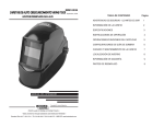
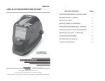
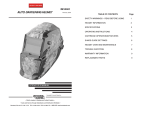
IM10002
VIKING™ 700G AUTO-DARKENING HELMETS
October, 2009
OPERATOR’S MANUAL
Copyright © Lincoln Global Inc.
• World's Leader in Welding and Cutting Products •
• Sales and Service through Subsidiaries and Distributors Worldwide •
Cleveland, Ohio 44117-1199 U.S.A. TEL: 216.481.8100 FAX: 216.486.1751 WEB SITE: www.lincolnelectric.com
TABLE OF CONTENTS
Page
SAFETY WARNINGS – READ BEFORE USING
1
HELMET INFORMATION
2
SPECIFICATIONS
3
OPERATING INSTRUCTIONS
4
CARTRIDGE OPERATIONS/FEATURES
5
SHADE GUIDE SETTINGS
6
HELMET CARE AND MAINTENANCE
7
TROUBLE SHOOTING
8
WARRANTY INFORMATION
9
REPLACEMENT PARTS
9
SAFETY WARNINGS – READ BEFORE USING
WARNING
HELMET INFORMATION
This Auto-Darkening Welding Helmet will automatically change from a light
state (shade 3.5) to a dark state (Shade 9-13) when arc welding starts.
The filter automatically returns to a light state when the arc stops.
Shade control adjustments can be made while welding.
ARC Rays can injure eyes and burn skin
• Before welding, always inspect helmet and filter lens to be sure they are fitted
properly, in good condition and not damaged.
• Check to see that the clear lens is clean and securely attached to the helmet.
• Always wear safety glasses or goggles under the welding helmet and protective
clothing to protect your skin from radiation, burns and spatter.
• Ensure that optical radiation from other welder’s arcs in the immediate area
does not enter in from behind the helmet and auto-darkening filter.
Note: Auto-darkening filters in Lincoln helmets are designed to protect the user against harmful
ultra-violet and infrared rays both in the dark and light states. No matter what shade the filter is
set to, the UV/IR protection is always present.
FUMES AND GASES can be dangerous to your health.
• Keep your head out of fumes.
• Use enough ventilation or exhaust at the arc or both to keep fumes and gases
from your breathing zone and general area.
• When welding with electrodes which require special ventilation such as
stainless or hard facing (see instructions on container or MSDS) or on
lead or cadmium plated steel and other metals or coatings which produce highly toxic fumes, keep exposure as low as possible and within
applicable OSHA PEL and ACGIH TLV limits using local exhaust or
mechanical ventilation. In confined spaces or in some circumstances,
outdoors, a respirator may be required. Additional precautions are also
required when welding on galvanized steel.
Match your welding application to the shade indicated on the shade chart.
(See Page 6)
• Operating temperature: 14°F ~ 131°F
(-10°C ~ 55°C).
• Do not use or open the auto-darkening filter if damaged by shock, vibration or pressure.
• Keep the sensors and solar cell clean. Clean the filter cartridge using a
soapy water solution and soft cloth which should be damp but not saturated.
This Auto-Darkening Welding Helmet is designed for use with GMAW, GTAW,
MMAW welding, or Plasma Arc and air carbon arc cutting.
The cartridge provides protection from harmful UV and IR radiation, in both
dark and light states.
The cartridge contains two sensors to detect the light from the welding arc,
resulting in the lens darkening to a selected welding shade.
• Do not use solvents or abrasive cleaning detergent.
• If cover lens is spattered or covered with dirt, it should be replaced immediately.
• Use only replacement parts specified in this manual.
• Do not use the helmet without inside and outside cover lenses properly
installed.
Refer to http://www.lincolnelectric.com/safety
for additional safety information.
1
2
SPECIFICATIONS
OPERATING INSTRUCTIONS
Headgear Adjustment
LCD Viewing Area
96 x 47mm (3.78 x 1.85in.)
Cartridge size
110 x 90mm (4.33 x 3.54in.)
UV/IR Protection
Up to Shade DIN 16 at all times
Arc Sensors
2
Light State Shade
DIN 4
Variable Welding Shades
DIN 9 to 13 and Grind
Shade Control
External knob - full adjustment
Power Supply
Solar cells - no battery required
Power On/Off
Fully automatic
Light to Dark Switching Time
0.00004 sec. (1/25,000 sec.)
Sensitivity Control
Variable
Delay Control (Dark to Light)
.1 sec. min. ~ 1.0 sec. max.
TIG Rating
5 amps
Operating Temperature
14°F ~ 131°F (-10°C ~ 55°C)
Storage Temperature
-4° ~ 158°F (-20°C ~ 70°C)
Total Weight
Black 505g (17.8 Oz.)
Graphic 520g (18.3 Oz.)
Compliance(1)
ANSI Z87.1-2003/CSA Z94.3
(1)
TILT ADJUSTMENT
CROWN
ADJUSTMENT
RATCHET KNOB
PIN HOLES FOR
ADJUSTMENT
Head Size Adjustment: Headband tightness is adjusted by pushing in the
ratchet knob and turning to adjust to desired comfort level. This knob is
located at the back of the helmet. HEAD GEAR CROWN ADJUSTMENT is
made by adjusting crown strap for vertical placement on the head and snapping the pin into the hole to lock securely in place.
Tilt: Tilt is adjusted on the left side of the helmet. TILT is adjusted by loosening outside tension knob and releasing the adjustment lever from its current location and moving it to another location. Retighten the outside tension
knob when finished.
Headgear compliance with ANSI Z87.1 is without sweatband installed.
3
4
CARTRIDGE OPERATION/FEATURES
Variable Shade Control
The shade can be adjusted from shade 9 to 13 based upon welding process or
application (refer to Shade selection chart on page 6). The variable shade control
knob is mounted on the exterior of the helmet shell. Grind mode can be selected
by rotating the shade control knob counterclockwise till an audible click is heard.
Grind mode is intended for grinding only not for welding.
ALWAYS TEST TO BE SURE THE ADF CARTRIDGE IS CHARGED
BEFORE WELDING. The helmet can be placed in sunlight to charge. Do not
store the helmet in a dark cabinet or other storage area for long periods.
While welding, the arc also charges the ADF cartridge.
SHADE GUIDE SETTINGS
GUIDE FOR SHADE NUMBERS
ELECTRODE SIZE
1/32 in. (mm)
ARC
CURRENT (A)
MINIMUM
PROTECTIVE
SHADE
SUGGESTED(1)
SHADE NO.
(COMFORT)
Less than 3 (2.5)
3-5 (2.5–4)
5-8 (4–6.4)
More than 8 (6.4)
Less than 60
60-160
160-250
250-550
7
8
10
11
–
10
12
14
Gas metal arc
welding and flux
cored arc welding
Less than 60
60-160
160-250
250-500
7
10
10
10
–
11
12
14
Gas tungsten arc
welding
Less than 50
50-150
150-500
8
8
10
10
12
14
Less than 500
500-1000
10
11
12
14
Less than 20
20-100
100-400
400-800
6
8
10
11
6 to 8
10
12
14
Less than 300
300-400
400-800
8
9
10
9
12
14
Torch brazing
–
–
3 or 4
Torch soldering
–
–
2
–
–
14
OPERATION
NT 1
Sensitivity Knob
You can adjust the light sensor by turning the Sensitivity knob to the left or right as
shown in figure below. Generally, turning the knob all the way to the right, or the
highest setting, is selected for normal use. When the helmet is used in the presence of excess ambient light or with another welding machine close by, improved
helmet performance can be obtained with a lower setting turning the knob to the
left to reduce the sensitivity.
Delay Time Knob
This control is designed to protect the welder’s eyes from the strong residual rays
after welding. Changing the Delay Time knob will vary dark to light time between
.1 second (minimum) to 1.0 second (maximum). Turning the Delay Time knob to
the left is maximum (1.0 second). This setting is recommended for high amperage applications where the weld puddle is still very bright after the welding arc
has ceased and for situations where the filter may be temporarily blocked from
seeing the welding arc.
Solar Power
This helmet is powered by solar energy. There are no user replaceable batteries.
S 27978-6
700G ADF
Shielded metal arc
welding
Air carbon
Arc cutting
(Light)
(Heavy)
Plasma arc welding
Plasma arc cutting
(2)
(Light)
(2)
(Medium)
(Heavy)(2)
Carbon arc welding
in.
PLATE THICKNESS
mm
Gas welding
Light
Medium
Heavy
Under 1/8
1/8 to 1/2
Over 1/2
Under 3.2
3.2 to 12.7
Over 12.7
4 or 5
5 or 6
6 or 8
Oxygen cutting
Light
Medium
Heavy
Under 1
1 to 6
Over 6
Under 25
25 to 150
Over 150
3 or 4
4 or 5
5 or 6
(1) As a rule of thumb, start with a shade that is too dark, then go to a lighter shade which gives sufficient view of the weld zone without going
below the minimum. In oxyfuel gas welding or cutting where the torch produces a high yellow light, it is desirable to use a filter lens that absorbs
the yellow or sodium line the visible light of the (spectrum) operation .
(2) These values apply where the actual arc is clearly seen. Experience has shown that lighter filters may be used when the arc is hidden by the
workpiece.
Data from ANSI Z49.1-2005
If your helmet does not include any one of the shades referenced above, it is
recommended you use the next darker shade.
Variable shade
Control Knob
5
6
HELMET CARE AND MAINTENANCE
TROUBLE SHOOTING GUIDE
Replacing Front Clear Lens: Replace the front cover lens if it is damaged –
cracked, soiled or pitted. Place your finger or thumb into recess (C) at the
bottom edge of the cover lens and flex the lens upwards until it releases from
the edges marked A and B. (Refer to figure 1). Use only the replacement
front cover lenses specified in this manual.
Test your shade cartridge prior to welding by directing the front of the cartridge toward a bright source of light. Then, using your fingers, rapidly cover
and uncover the sensors. The cartridge should darken momentarily as the
sensor is exposed. A torch striker can also be used.
POSSIBLE CAUSE
SOLUTION
PROBLEM
Replace the Inside Clear Lens: If it is damaged (cracked, soiled or pitted).
Place your fingernail in recess above cartridge view window and flex lens
upwards until it releases from edges of cartridge view window.
Difficult to see through filter. Front cover lens dirty.
Cartridge dirty.
Change the Shade Cartridge (See figure 2)
Fitting New Cartridge: Take the new shade cartridge and pass the potentiometer cable under the wire loop before placing the cartridge into its retaining frame inside the helmet. Lower the wire loop and ensure the front edge of
the loop (D) is properly retained under the retaining lugs (E) as shown in (figure 3).
Filter does not darken when Sensitivity is set too low.
arc is struck.
Front cover lens dirty.
Position the shade potentiometer inside of the helmet with the shaft protruding through the hole. From outside of the helmet, position dial panel onto the
potentiometer shaft and secure potentiometer to shell, rotate shaft counterclockwise until an audible click is heard and install shade control knob with
pointer positioned at Grind location on dial panel.
Cleaning: Clean the helmet by wiping with a soft cloth. Clean cartridge surfaces regularly. Do not use strong cleaning solutions. Clean sensors and
solar cells with soapy water solution and a clean cloth and wipe dry with a
lint-free cloth. Do NOT submerge shade cartridge in water or other solution.
Filter darkening without arc
being struck.
Filter remains dark after
completing a weld.
Storage: Store in a clean, dry location.
Figure 2
7
Clean the Auto-Darkening cartridge
with soapy water solution and soft
cloth.
Adjust sensitivity to required level.
Clean or replace front cover lens.
Front cover lens is damaged.
Check for cracked or pitted front
cover lens and replace as required.
Sensors are blocked or Solar
panel is blocked.
Make sure you are not blocking the
sensors or solar panels with your arm
or other obstacle while welding.
Adjust your position so that the sensors can see the weld arc.
Grind Mode Selected
Make sure proper shade is selected.
Sensitivity set too high.
Adjust sensitivity to required
level.
Adjust delay time to required
level.
Delay time set too high.
WARNING
ADF is
cracked.
Figure 1
Clean or replace front cover lens.
Figure 3
Cease (STOP) using this product if this problem
exists. UV/IR protection may be compromised
resulting in burns to the eyes and skin.
Weld spatter Missing, damaged,
is damaging broken, cracked or
distorted front cover
the filter.
lens.
8
Replace front cover lens
as needed.
WARRANTY INFORMATION
WARRANTY INFORMATION: Reference IMWS1 included in Literature.
SPATTER DAMAGE IS NOT COVERED BY WARRANTY:
Do not use this product without the correct protective clear lenses installed
properly on both sides of the Auto-Darkening Filter cartridge (ADF). The clear
lenses supplied with this helmet are properly sized to work with this product
and substitutions from other suppliers should be avoided.
REPLACEMENT PARTS
4
HELMET
SHELL
3
1
2
ITEM
1
2
3
4
5*
PART NO.
KP2913-1
KP2853-1
KP2897-1
KP2851-1
DESCRIPTION
OUTSIDE CLEAR LENS
(PKG QTY: 5)
ADF CARTRIDGE
INSIDE CLEAR LENS
(PKG QTY: 5)
HEADGEAR ASSEMBLY
(INCLUDING SWEATBAND)
KP2854-1 SWEATBAND
(PKG QTY: 2)
QTY
1
1
1
1
1
*Not illustrated
• World's Leader in Welding and Cutting Products •
9
• Sales and Service through Subsidiaries and Distributors Worldwide •
Cleveland, Ohio 44117-1199 U.S.A. TEL: 216.481.8100 FAX: 216.486.1751 WEB SITE: www.lincolnelectric.com