1
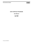
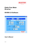
Flow Computer Division
Annubar Flow Calculation Program
(For the FloBoss™ 407 Flow Manager
and ROC300-Series Remote Operations Controller)
User Manual
(QER 01Q032)
Form A6120
January 2006
Annubar Flow Calculation Program User Manual
Revision Tracking Sheet
January 2006
This manual may be revised periodically to incorporate new or updated information. The revision date
of each page appears at the bottom of the page opposite the page number. A change in revision date to
any page also changes the date of the manual that appears on the front cover. Listed below is the
revision date of each page (if applicable):
Page
All pages
All pages
All pages
Ii, 10, 13-17
All pages
Revision
Jan-06
Sep-03 (Rev 4)
Jul-03 (Rev 3)
Nov-01 (Rev 2)
Oct-01 (Rev 1)
FloBoss and ROCLINK are marks of one of the Emerson Process Management companies. The Emerson logo is a trademark and service
mark of Emerson Electric Co. All other marks are the property of their respective owners.
© Fisher Controls International, LLC. 2001-2006. All rights reserved. Printed in the U.S.A.
www.EmersonProcess.com/flow
While this information is presented in good faith and believed to be accurate, Fisher Controls does not guarantee satisfactory results from
reliance upon such information. Nothing contained herein is to be construed as a warranty or guarantee, express or implied, regarding the
performance, merchantability, fitness or any other matter with respect to the products, nor as a recommendation to use any product or process
in conflict with any patent. Fisher Controls reserves the right, without notice, to alter or improve the designs or specifications of the products
described herein.
Rev: Jan-06
ii
Annubar Flow Calculation Program User Manual
Table of Contents
Page
1 INTRODUCTION ................................................................................................................................. 1
1.1 Scope and Organization ........................................................................................................... 1
1.2 Product Overview .................................................................................................................... 1
1.2.1 Annubar Flow Algorithm.......................................................................................... 2
1.3 Program Requirements............................................................................................................. 3
2 INSTALLATION .................................................................................................................................. 4
2.1 Customizing ROCLINK 800 ................................................................................................... 4
2.2 Downloading the Program ....................................................................................................... 4
3 CONFIGURATION............................................................................................................................. 10
3.1 Annubar Calculation Configuration Screen........................................................................... 12
3.2 Saving the Configuration ....................................................................................................... 14
4 REFERENCE MATERIALS............................................................................................................... 16
4.1 Softpoint Parameters.............................................................................................................. 16
4.2 Annubar User Defined Points ................................................................................................ 16
4.3 Annubar Pipe ID and Flow Coefficients (K) ......................................................................... 17
Rev: Jan-06
iii
Annubar Flow Calculation Program User Manual
1 INTRODUCTION
1.1 Scope and Organization
This document serves as the user manual for the Annubar Flow Calculation Program (QER 01Q032),
which is intended for use in a FloBoss™ 407 Flow Manager or a ROC300-Series FlashPAC unit. This
manual describes how to download and configure this program (referred to as the “Annubar program” or
“the program” throughout the rest of this manual). You access and configure this program using
ROCLINK™ 800 Configuration Software (version 1.50 or greater) loaded on an IBM-compatible
personal computer running Windows® 98, ME, NT 4.0 (with Service Pack 6), 2000 (with Service Pack
2), or XP.
The sections in this manual provide information in a sequence appropriate for first-time users. Once you
become familiar with the procedures and the software running in a FloBoss 407 or ROC300-Series unit,
the manual becomes a reference tool.
This manual has the following major sections:
♦
♦
♦
♦
Section 1 – Introduction
Section 2 – Installation
Section 3 – Configuration
Section 4 – Reference Materials
This manual assumes that you are familiar with the FloBoss 407 and ROC300-Series FlashPAC units
and their configuration. For more information, refer to:
♦
♦
♦
♦
FloBoss 407 Flow Manager Instruction Manual (Form A6013).
ROCLINK 800 Configuration Software User Manual (Form A6121).
ROC306/312 Remote Operations Controller Instruction Manual (Form A4630)
ROC364 Remote Operations Controller Instruction Manual (Form A4193)
Note: When the text applies to both the ROC300-Series and the FloBoss 407, we use the generic term
“ROC.” If differences are present, we indicate those differences by device name.
1.2 Product Overview
The Annubar Flow Calculation Program enables both ROC300-Series with FlashPAC and FloBoss 407
units to perform flow calculations for meter runs implementing an Annubar end element. The program
allows the same ROC to calculate, in parallel, the Annubar flow calculations and orifice and turbine
flow calculations.
The program enables the ROC to calculate volumetric flow given differential and static pressure from an
Annubar end element. The program also calculates energy rate, accumulates flow and energy, and
provides the ability to archive flow and energy totals in the historical database.
Rev: Jan-06
1
Annubar Flow Calculation Program User Manual
1.2.1 Annubar Flow Algorithm
As implemented in this program, following is the algorithm for Annubar volumetric flow rate of a gas at
standard conditions:
Qv = C'[hwPf]0.5
Where:
Qv = Volumetric flow rate of gas at standard conditions
hw = Differential pressure
Pf = Absolute static pressure (flowing)
C' = FNA * K * D2 * Fr * Ya * Fpb * Ftb * Ftf * Fgr * Fpv * Fa
Where:
FNA = Units conversion factor
K = Annubar flow coefficient
D = Internal pipe diameter
Fr = Reynolds number factor
Ya = Annubar expansion factor
Fpb = Pressure base factor
Ftb = Temperature base factor
Ftf = Flowing temperature factor
Fgr = Specific gravity factor
Fpv = Supercompressibility factor
Fa = Thermal expansion factor
The calculation is identical to the AGA 3 (orifice) calculation with the following exceptions:
Basic Orifice Factor (Fb) - The AGA 3 calculation defines the basic orifice factor as follows:
Fb = 338.178d2Ko
Where:
d = Orifice diameter
Ko = The flow coefficient when the orifice Reynolds Number is infinitely large.
This is roughly equivalent to the first three factors in the Annubar equation. The value 338.178 is equivalent
to the FNA factor in the Annubar equation to convert the flow to units of SCFH. The square of the orifice
diameter (d2) has been replaced with the square of the internal pipe diameter (D2) and the flow coefficient
(K) is the actual flow coefficient determined from Table 2.1 of the Annubar Flow Handbook, rather than the
coefficient at an infinitely large Reynolds Number (Ko). The result of multiplying FNA*D2*K is stored in the
Fb parameter.
Reynolds Number Factor (Fr) - Because the flow coefficient in the Annubar equation is the actual flow
coefficient, the Reynolds number factor is not required and will always equal 1.0.
Rev: Jan-06
2
Annubar Flow Calculation Program User Manual
Expansion Factor (Y) - The expansion factor for Annubars is calculated as follows:
Y = 1 - ((1-B)20.011332 - 0.00342) hw/Pfk
B = 4d/πD
Where:
B = Blockage factor
D = Internal pipe diameter
d = Annubar diameter
hw = Differential pressure
Pf = Absolute static pressure (flowing)
k = Ratio of specific heats (1.3 for gases)
Supercompressibility (Fpv) – The compressibility factor is calculated using the method defined in the
meter run setup.
All of the calculated factors, referenced above, may be viewed in softpoint parameters when the
softpoint enable flag is set to a valid softpoint number. See Section 4.1 for a description and location of
values written to the softpoint.
1.3 Program Requirements
You download the Annubar program to—and then run it from—the Flash memory on the ROC. You
configure the program functions by point type and parameter using the ROCLINK 800 Configuration
software. The program is compatible with version 1.10 (or greater) of the FloBoss 407 and with version
2.20 (or greater) of the ROC300-Series FlashPAC.
Based on the available memory (see Section 2.2) or other user task requirements, select one of the
programs listed below. Program specifics include:
Program Name
User
Task
Code Area
Data Area
UDP
ROC or FloBoss Version
FP1_ABAR.H00
User 1
D0000-D3FFF
B0000-B3FFF
30
ROC300-series FlashPAC
FP3_ABAR.H00
User 3
D8000-DBFFF
B8000-BBFFF
29
ROC300-series FlashPAC
FB1_ABAR.H00
User 1
B0000-B3FFF
60000-63FFF
30
FloBoss 407
FB3_ABAR.H00
User 3
B8000-BBFFF
70000-73FFF
29
FloBoss 407
FB4_ABAR.H00
User 4
C8000-CBFFF
74000-77FFF
29
FloBoss 407
Note: You must connect a PC to the ROC unit’s LOI port before starting the download.
For information on viewing the memory allocation of user programs, refer to the ROCLINK 800
Configuration Software User Manual (Form A6121).
Rev: Jan-06
3
Annubar Flow Calculation Program User Manual
2 INSTALLATION
This section provides instructions for installing the Annubar program using version 1.50 (or greater) of
the ROCLINK 800 Configuration software. Read Section 1.3 of this manual for program requirements.
2.1 Customizing ROCLINK 800
Before downloading the user program, you must apply two custom files to ROCLINK 800. This enables
you to access the Annubar Calculation configuration screen.
Note: Apply this customization to ROCLINK 800 before you download the user program.
To apply the file:
1. Navigate to the CD-ROM folder in which the installation files are located. Custom ROCLINK
800 files are typically located in the ROCLINK Files folder on the CD-ROM.
2. Select and copy the following two files:
♦
♦
Annubar Calc Pt 29.DSP.
Annubar Calc Pt 30.DSP.
3. Paste the files into the default ROCLINK Displays folder. This is typically C:\Program
Files\ROCLINK800\Displays. This completes the customization.
2.2 Downloading the Program
This section provides instructions for installing the user program into the Flash and ROM memory on
the ROC.
To download the user program:
1. Connect the ROC to your computer using the LOI port.
2. Start and logon to ROCLINK 800.
3. Select Utilities > User Program Administrator from the ROCLINK menu bar. The User
Program Administrator screen displays:
Rev: Jan-06
4
Annubar Flow Calculation Program User Manual
Figure 1. User Program Administrator Screen
4. Review the screen, paying special attention to the Memory Usage frame and the unused memory
blocks display.
Field
Description
User Programs Installed in
Device
This display-only frame identifies any programs currently installed in the
ROC. The program provides this name during installation.
Status
This display-only field indicates the current status of the program. Valid
values are ON or OFF.
Memory Usage
This display-only frame shows the current memory allocation by
segment.
Note: You must have the following sufficient available (non-allocated)
memory in order to successfully load the Annubar program:
For the FloBoss 407 (version ≥1.10) load one of the following:
Program Name
COMM
Port
Code Area
Data Area
FB1_ABAR.H00
User 1
B0000-B3FFF
60000-63FFF
FB3_ABAR.H00
User 3
B8000-BBFFF
70000-73FFF
FB4_ABAR.H00
User 4
C8000-CBFFF
74000-77FFF
For the ROC300-Series (version ≥2.20) load one of the following:
Program Name
Rev: Jan-06
COMM
Port
Code Area
Data Area
FP1_ABAR.H00
User 1
D0000-D3FFF
B0000-B3FFF
FP3_ABAR.H00
User 3
D8000-DBFFF
B8000-BBFFF
5
Annubar Flow Calculation Program User Manual
Note: Contact your sales representative if you cannot load the program
due to current memory block usage.
Field
Description
Download User Program
File
This display-only frame identifies the programs you have selected for
download, along with the Code and Data segment information (see
Figure 3).
5. Identify (based on your device and current memory allocations) the appropriate program to use.
6. Click Browse in the Download User Program File frame. The Select User Program File screen
displays (see Figure 2).
7. Select the path and user program file to download from the CD-ROM. (Program files are
typically located in the Program Files folder on the CD-ROM). As Figure 2 shows, the screen
lists all valid user program files with the .H00 extension:
Figure 2. Select User Program File
8. Click Open to select the program file. The User Program Administrator screen displays. As
shown in Figure 3, note that the Download User Program File frame identifies the selected
program and that the Download & Start button is active:
Rev: Jan-06
6
Annubar Flow Calculation Program User Manual
Figure 3. User Program Administrator Screen
9. Click Download & Start to begin loading the selected programs. The following message
displays:
Figure 4. Confirm Download
10. Click Yes to begin the download. During the download, the program performs a Warm Start,
creates an event in the Event Log, and—when the download completes—displays the following
message:
Rev: Jan-06
7
Annubar Flow Calculation Program User Manual
Figure 5. ROCLINK 800 Download Confirmation
Note: If you are running ROCLINK 800 version 1.50 or earlier, the following warning may
display. Click OK to continue.
Figure 6. Device Type and Firmware Warning
11. Click OK. The User Program Administrator screen displays (see Figure 7). Note that:
♦ The User Programs Installed in Device frame identifies the installed program.
♦ The Memory Usage frame reflects the use of system memory.
♦ The message Download & Start User Program COMPLETED appears at the bottom of the
screen.
Rev: Jan-06
8
Annubar Flow Calculation Program User Manual
Figure 7. User Program Administrator Screen
12. Click Close. The ROCLINK 800 screen displays and the download is complete.
Figure 8. ROCLINK 800 Screen
Rev: Jan-06
9
Annubar Flow Calculation Program User Manual
3 CONFIGURATION
After you have successfully downloaded the Annubar program, you configure the program using the
ROCLINK 800 software.
Note: This program uses the standard ROC meter run point types. You configure all meter run setup—
with the exception of enabling the Annubar calculation itself—through the standard ROCLINK meter
configuration screens (including general meter setup, input definitions, advanced setup, gas quality, and
history setup configuration for the meter run).
To access the Annubar Calculation configuration screen:
1. From the ROCLINK 800 menu bar, select Configure > User Data > Annubar Calc Pt. The
Annubar Calculation configuration screen displays (see Figure 10).
Note: You can also access the Annubar Calculation configuration screen using the configuration
tree on the left side of the screen. Click the + next to the User Data option, click the + next to the
Annubar Calc option, and then double-click the meter run you want to configure.
Figure 9. ROCLINK 800
2. Complete the program’s configuration (refer to Section 3.1) based on your organization’s
requirements.
Rev: Jan-06
10
Annubar Flow Calculation Program User Manual
Note: If the screen shown in Figure 10 does not display, you have not correctly customized
ROCLINK 800. Refer to Section 2.1.
Figure 10. Annubar Calculation Configuration
Rev: Jan-06
11
Annubar Flow Calculation Program User Manual
3.1 Annubar Calculation Configuration Screen
Use this screen to set the calculation specifics.
1. From the ROCLINK 800 menu bar, select Configure > User Data > Annubar Calc Pt. The
Annubar Calculation configuration screen displays.
Figure 11. Annubar Calculation Configuration screen
2. Review—and change as necessary—the values in the following fields:
Field
Description
Point Number
Selects the meter run to configure. The number of available meter runs varies by
device: 3 in the ROC306/312, 4 in the FloBoss 407, or 5 in the ROC364.
Annubar
Calculation
Applies the Annubar calculation for this meter run. Valid values are Enabled (which
activates the calculation) or Disabled (which deactivates the calculation). When you
disable the Annubar calculation, the ROC executes the AGA flow calculation for the
meter run.
Note: You can configure Annubar, orifice, and turbine type meter runs in any
combination on the ROC.
Calc Time
(Seconds)
This read-only field monitors, in seconds, the period during which the program
performs the Annubar calculations (reading inputs, calculating instantaneous rates,
and updating accumulations) for the meter.
Softpoint
Transfer
Identifies the softpoint to which the program copies flow calculation data (which a
host system or FST can subsequently access). Valid values are 0 (disable the
softpoint write) or 1 to 32 (allow the write to the specific softpoint).
Note: Refer to Section 4.1 for a description and location of the data written to the
designated softpoint.
Rev: Jan-06
12
Annubar Flow Calculation Program User Manual
Field
Description
Annubar Flow
Coefficient
Indicates whether the program determines the flow coefficient value for the Annubar
calculation or uses a value you enter. Click the appropriate radio button.
Note: If you select Entered by User, you must enter the flow coefficient value in the
provided field.
Differential
Pressure
This read-only field displays, in inches of H20, the value of differential pressure used
for the Annubar flow calculation.
Static
Pressure
This read-only field displays, in PSI, the value of static pressure used for the
Annubar flow calculation.
Flowing
Temperature
This read-only field displays, in degrees F, the value of flowing temperature used for
the Annubar flow calculation.
Volume
This read-only field displays the instantaneous flow (in MCF/day) for the Annubar
flow calculation.
Note: You can view other calculated flow parameters (such as today’s flow or
yesterday’s total) from the ROCLINK I/O Monitor screen (View > I/O Monitor or
Meter > Values).
Energy
This read-only field displays the instantaneous energy (in MMBTU/day) for the
Annubar flow calculation.
Note: You can view other calculated flow parameters (such as today’s flow or
yesterday’s total) from the ROCLINK I/O Monitor screen (View > I/O Monitor or
Meter > Values).
Auto Scan/
Stop Scan
Enables/disables automatic refresh of the information on the screen at a one-second
interval.
Update
Refreshes all information on the screen.
Close
Closes the window and returns to the ROCLINK 800 screen.
Apply
Writes data entered on the screen for use in the program.
3. Click Apply to save any changes. Go to Section 3.2.
Rev: Jan-06
13
Annubar Flow Calculation Program User Manual
3.2 Saving the Configuration
Whenever you modify or change the configuration, it’s a good practice to save the final configuration to
non-volatile memory. To save the configuration:
1. Select ROC > Flags. The Flags screen displays:
Figure 12. Flags screen
2. Click Save Configuration. A verification message displays:
Figure 13. Perform screen
Rev: Jan-06
14
Annubar Flow Calculation Program User Manual
3. Click Yes. A confirmation message displays:
Figure 14. Flags screen
4. Click OK to begin the save process. The Status field on the Flags screen displays In Progress.
Note: Depending on the size and complexity of the user program, this process may take several
minutes. When the process ends, the Status field on the Flags screen displays Completed.
5. Click Update on the Flags screen. This completes the process of saving your new configuration.
Rev: Jan-06
15
Annubar Flow Calculation Program User Manual
4 REFERENCE MATERIALS
4.1 Softpoint Parameters
The following table identifies the units of measure associated with each input and output of the steam
calculation program.
Table 1. Annubar Calculation Program Softpoints
Parameter
Data 1
Data 2
Data 3
Data 4
Data 5
Data 6
Data 7
Data 8
Data 9
Data 10
Data 11
Data 12
Data 13
Data 14
Data 15
Data 16
Data 17
Data 18
Data 19
Data 20
Description
Differential pressure (Inches H20)
Static pressure (PSI)
Flowing temperature (Deg F)
Flow rate (MCF/DAY)
Energy rate (MMBTU/DAY)
Pressure Extension (HwPf)
Correction Factor (C’)
Calculation period (Seconds)
Annubar flow coefficient (K)
Expansion factor (Y)
Base pressure factor (Fpb)
Base temperature factor (Ftb)
Flowing temperature factor (Ftf)
Specific gravity factor (Fgr)
Compressibility factor (Fpv)
Thermal expansion factor (Fa)
Basic orifice factor (Fb)
Intermediate variable (Forif)
Intermediate variable (Ky)
Diameter ratio (beta)
4.2 Annubar User Defined Points
For User Task 1, the point type is 30. For User Task 3 or User Task 4, the point type is 29.
Table 2. Annubar Flow Calculation User Defined Points
Parameter
Number
0
1
2
3
4
5
6
7
8
9
10
11
12
13
14
15
Rev: Jan-06
ReadWrite
R/W
R/W
R/O
R/O
R/O
R/O
R/O
R/O
R/O
R/O
R/W
R/W
R/O
R/O
R/O
R/O
Data
Type
Byte
Byte
Float
Float
Float
Float
Float
Float
Float
Float
Byte
Float
Float
Float
Float
Float
Length
1
1
4
4
4
4
4
4
4
4
1
4
4
4
4
4
Description
Annubar calculation enable
Softpoint write enable
Differential pressure
Static pressure
Flowing Temperature
Flow rate (MCF/DAY)
Energy rate (MMBTU/DAY)
Pressure Extension (HwPf)
Correction Factor (C’)
Calculation period (Seconds)
Calc/Enter flow coefficient flag
Annubar flow coefficient (K)
Expansion factor (Y)
Base pressure factor (Fpb)
Base temperature factor (Ftb)
Flowing temperature factor (Ftf)
16
Annubar Flow Calculation Program User Manual
Parameter
Number
16
17
18
19
20
21
22
ReadWrite
R/O
R/O
R/O
R/O
R/O
R/O
R/O
Data
Type
Float
Float
Float
Float
Float
Float
Float
Length
4
4
4
4
4
4
4
Description
Specific gravity factor (Fgr)
Supercompressibility factor (Fpv)
Thermal expansion factor (Fa)
Basic orifice factor (Fb)
Intermediate variable (Forif)
Intermediate variable (Ky)
Diameter ratio (beta)
4.3 Annubar Pipe ID and Flow Coefficients (K)
Following are reference tables for Annubar probe diameters (D). Use the actual probe diameter if not
listed.
Table 3. Annubar Probe Diameters
Model
10
15/16
25/26
35/36
45/46
Diameter (d)
0.183
0.3576
0.846
1.23
1.98
Table 4. Pipe ID and Flow Coefficients: Type 10
Nom Pipe
Size, Inch
½
¾
1
1-1/4
1-1/2
2
Schedule
40
40
80
40
80
40
80
40
80
40
Pipe ID
0.622
0.824
0.957
1.049
1.278
1.36
1.5
1.61
1.939
2.067
K
0.4265
0.5067
0.5547
0.5547
0.587
0.587
0.603
0.603
0.6197
0.6197
Table 5. Pipe ID and Flow Coefficients: Type 15/16
Nom Pipe
Size, Inch
2
Rev: Jan-06
Schedule
XX-STG
160
80
-
Pipe ID
1.503
1.689
1.939
2
K
0.5627
0.5746
0.5865
0.5888
17
Annubar Flow Calculation Program User Manual
Nom Pipe
Size, Inch
2-1/2
3
3-1/2
4
5
Schedule
40
XX-STG
160
80
40
XX-STG
160
80
40
XX-STG
80
40
XX-STG
160
80
40
XX-STG
160
80
40
Pipe ID
2.067
1.771
2.125
2.323
2.469
2.5
2.3
2.624
2.9
3
3.068
2.728
3.364
3.5
3.548
3.152
3.438
3.826
4
4.026
4.063
4.313
4.813
5
5.047
K
0.5912
0.5789
0.5932
0.599
0.6026
0.6033
0.5984
0.6059
0.6109
0.6124
0.6134
0.6079
0.6172
0.6187
0.6192
0.6146
0.618
0.6216
0.6233
0.6235
0.6237
0.6255
0.6285
0.6295
0.6297
Table 6. Pipe ID and Flow Coefficients: Type 25/26
Nom Pipe
Size, Inch
4
5
6
Rev: Jan-06
Schedule
XX-STG
80
40
XX-STG
160
80
40
XX-STG
160
80
40
Pipe ID
3.152
3.826
4
4.026
4.063
4.313
4.813
5
5.087
4.987
5.189
5.761
6
6.065
K
0.548
0.5704
0.5747
0.5753
0.5762
0.5814
0.5901
0.5928
0.5934
0.5926
0.5953
0.6018
0.6014
0.6047
18
Annubar Flow Calculation Program User Manual
Nom Pipe
Size, Inch
8
10
12
14
16
18
20
24
30
36
42
Rev: Jan-06
Schedule
160
XX-STG
80
40
160
80
X-STG
40
160
80
X-STG
40
STD
80
X-STG
40
STD
80
40
STD
80
X-STG
STD
80
X-STG
STD
X-STG
STD
X-STG
STD
X-STG
STD
X-STG
STD
-
Pipe ID
6.813
6.875
7.625
7.981
8
8.5
9.564
9.75
10
10.02
10.126
11.376
11.75
11.938
12
12.5
13
13.124
13.25
14
14.314
15
15.25
16
16.126
17
17.25
18
17.398
19
19.25
20
23
23.25
24
29
29.25
30
35
35.25
36
41
41.25
42
K
0.6105
0.611
0.6155
0.6173
0.6174
0.6196
0.6236
0.6242
0.6249
0.625
0.6253
0.6285
0.6293
0.6297
0.6298
0.6308
0.6317
0.6319
0.6319
0.6332
0.6337
0.6346
0.6349
0.6357
0.6359
0.6368
0.637
0.6377
0.6371
0.6385
0.6387
0.6392
0.641
0.6411
0.6415
0.6434
0.6435
0.6437
0.645
0.645
0.6452
0.6461
0.6461
0.6462
19
Annubar Flow Calculation Program User Manual
Table 7. Pipe ID and Flow Coefficients: Type 35/36
Nom Pipe
Size, Inch
12
14
16
18
20
24
30
36
42
48
60
72
84
96
Rev: Jan-06
Schedule
160
80
X-STG
40
STD
80
X-STG
40
STD
80
40
STD
80
X-STG
STD
80
X-STG
STD
80
S-STG
STD
X-STG
STD
X-STG
STD
X-STG
STD
-
Pipe ID
10.126
11.376
11.75
11.938
12
12.5
13
13.124
13.25
14
14.314
15
15.25
16
16.126
17
17.25
18
17.938
19
19.25
20
21.564
23
23.25
24
29
29.2503
30
35
36.25
36
41
41.25
42
48
60
72
84
96
K
0.6116
0.6165
0.6178
0.6184
0.6186
0.62
0.6214
0.6217
0.622
0.6238
0.6245
0.6259
0.6263
0.6276
0.6278
0.6292
0.6296
0.6306
0.6305
0.6318
0.6321
0.6329
0.6344
0.6355
0.6357
0.6363
0.6392
0.6393
0.6396
0.6415
0.6416
0.6418
0.6431
0.6432
0.6434
0.6445
0.6461
0.6472
0.6479
0.6485
20
Annubar Flow Calculation Program User Manual
If you have comments or questions regarding this manual, please direct them to your local sales representative or
contact:
Emerson Process Management
Flow Computer Division
Marshalltown, Iowa 50158 USA
Houston, TX 77065 USA
Pickering, North Yorkshire UK Y018 7JA
Website: www.EmersonProcess.com/flow
Rev: Jan-06
21