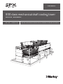
1
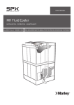
U S E R M A N UA L
800 class mechanical draft cooling tower
O P E R AT I O N - M A I N T E N A N C E
M95-1356B
I SSU E D 08/2013
R EAD AN D U N D E R STAN D TH I S MAN UAL PR IOR TO OPE RATI NG OR S E RVICI NG TH I S PROD UCT.
contents
The following defined terms are used throughout this manual to
bring attention to the presence of hazards of various risk levels, or
to important information concerning the life of the product.
Warning
Indicates presence of a hazard which can cause severe personal
injury, death or substantial property damage if ignored.
Caution
Indicates presence of a hazard which will or can cause personal
injury or property damage if ignored.
Note
Indicates special instructions on installation, operation or
maintenance which are important but not related to personal injury
hazards.
These instructions assist in obtaining efficient, long life from
Marley cooling equipment. Direct questions concerning cooling
tower operation and maintenance to your Marley sales office or
representative. Always include your tower serial number when
writing for information or ordering parts. Look for this number on
the nameplate near the access.
2
contents
General...........................................................................................................................4
Before Start-up.............................................................................................................5
Initial Starting Procedure............................................................................................7
Routine Starting Procedure.......................................................................................8
Operation.......................................................................................................................9
Freezing Weather Operation..................................................................................11
Temperature Control and Energy Management.................................................13
Maintenance...............................................................................................................15
Cleaning...................................................................................................................... 17
Water Treatment........................................................................................................18
Seasonal Shutdown Instructions..........................................................................20
Spare Parts and Accessories................................................................................21
Troubleshooting.........................................................................................................22
Safety...........................................................................................................................24
Inspection and Maintenance Schedule................................................................25
Inspection Checklist.................................................................................................26
3
general
A cooling tower, like any heat exchanger, exchanges all heat imposed upon
it from one fluid to another fluid. For a cooling tower, heat from the water is
put into the air. The plant process replenishes the heat to the water, typically
at another heat exchanger such as a condenser. A cooling tower differs from
many heat exchangers in that heat is transferred in two forms—sensible and
latent heat. As heat is transferred from the water, the air temperature increases
(sensible) and the air’s water content, or humidity, also increases (latent). As
the heat load, inlet air wet-bulb temperature, or airflow on a cooling tower
changes, the cooling tower will respond by finding a new equilibrium with the
process. The cooling tower will still dissipate all the heat from the process,
but at new water temperatures.
The cooling tower cold water temperature is the supply water temperature
to the condenser, and changes in the cold water temperature usually affect
efficiency of the plant output. Although the reduced cold water temperatures
that result from maximum fan power utilization are usually beneficial to plant
output, the amount of fan power affects the cost of running the cooling tower.
As these variables interact on a cooling tower, the operator must find the
proper trade-off between these opposing forces.
These instructions will assist in obtaining efficient, long life from Marley cooling
equipment. Direct questions concerning tower operation and maintenance to
your Marley sales office or representative. Always include your tower serial
number when writing for information or ordering parts. Look for this number
on the nameplate near the tower access.
4
operation
Before Start-up
Caution
Temporary safety barricades should be placed around any exposed
openings in the operating (or nonoperating) tower, fall protection
equipment should be worn by personnel where appropriate, and
other safety precautions should be taken in compliance with OSHA
regulations and standards.
Cleaning
Clean any nozzles that are clogged. Remove any sediment from the cold water
basin, sump and screens. Use a water hose to flush cold water basins. If you
are restarting or recommissioning a previously used tower, see Warning
note on page 17.
Inspection
It is imperative that all operating assemblies be inspected before they are
placed in operation. The following is a list of components to be checked
before starting the tower:
• Check drive shaft alignment. Realign if necessary. See Marley Drive Shaft
User Manual.
• Check tightness of bolts that attach mechanical equipment support to
the tower structure. Check tightness of bolts in fan cylinder joints and fan
cylinder anchorage.
• Check concrete structural surfaces for spalling and cracks. Repair as
necessary.
• Check tightness of the following bolted joints in the fan and drive
assemblies:
–Fan hub clamp bolts. See Marley Fan User Manual for correct torque
setting.
–Fan hub cover bolts, where applicable.
–Geareducer and motor mounting bolts.
–Drive shaft coupling and guard bolts.
• Check Geareducer oil for sludge or water by draining off and testing a sample
as outlined in the Marley Geareducer Service Manual. Check Geareducer oil
level at “oil level” mark on the side of the case. Add oil as required. The oil
level placard must be adjusted so that its “full” mark is at the same elevation
as the “full” mark on the side of the Geareducer case. Check oil lines to be
sure there are no leaks and all joints are tight. See Geareducer User Manual
for oil filling procedure and list of recommended lubricants.
➠
5
operation
• Rotate fan by hand to be sure of free rotation and ample tip clearance. See
Marley Fan User Manual.
• Check motor insulation with a “Megger.” See maintenance section of Marley
Electric Motor Service Manual.
• Lubricate the motor according to motor manufacturer’s instructions.
• Test run each fan separately for a short time. Check for excessive vibration
or unusual noise. If either is present, see Troubleshooting on pages 22
and 23 of this manual. Fan must rotate clockwise when viewed from above.
Recheck Geareducer oil level.
• Check functioning of make-up water supply.
• Make sure the blowdown or bleed-off will carry the proper amount of water. (See Blowdown on page 18.)
Operate Water System
Complete steps 1 thru 4 under Initial Starting Procedure on page 7.
Circulate water over the tower continuously for several days before starting
the mechanical equipment and putting the tower into continuous operation.
Caution
6
Do not circulate water over the tower in freezing weather without a
heat load. (See Caution note on page 8.)
operation
Initial Starting Procedures
1— Fill the cold water basin and circulating water system to a level 1/2”
(13 mm) below the overflow.
2— Bypass valve should be closed unless start-up is in cold weather. (See
Routine Starting Procedure on page 8.)
3— Prime and start the circulating water pumps one at a time. Increase the
flow of circulating water gradually to design water rate to avoid surges
or water hammer which could damage the distribution piping.
4— When flow has stabilized at or near the design rate, adjust water makeup to maintain the level that the water has pumped down to in the cold
water basin. (See Cold Water Collection Basin on page 10.) This
should coincide reasonably with the recommended operating water level
indicated on the Marley project drawings.
5— Start the fan(s). After 30 minutes operating time, to permit Geareducer oil
to come up to operating temperature, check motor load with watt meter, or
take operating volt and ampere readings and calculate motor horsepower.
Refer to Marley Fan User Manual for instructions.
Caution
If it is necessary to adjust fan pitch to pull correct contract
horsepower, measure results when circulating design water rate
at design hot water temperature. Horsepower will change with air
density. Lock out all electrical service before entering fan area.
7
operation
Routine Starting Procedure
After periods of routine shutdown, the following restarting procedure should
be followed:
• Start the circulating water pump(s). Increase the flow of circulating water
gradually to design water rate to avoid surges or water hammer which could
damage the distribution piping.
Caution
Circulating cold water over a tower in freezing weather will cause ice
to form, which may cause damage to the fill system. Water should be
bypassed directly to the cold water basin until the heat load causes
its temperature to rise above 70°F (21°C), at which time it may be
directed over the tower. Also, towers must not be operated with
reduced water rate and/or no heat load during freezing weather. If
a bypass is used, Do Not modulate.
• Start the fan(s). On multi-cell towers, only as many fans should be started as
are needed to produce the desired cold water temperature. If the tower is
equipped with two-speed motors, fans may be progressively started at half
speed, increasing to full speed as necessary to maintain the desired cold
water temperature. (See Temperature Control and Energy Management
on pages 13 and 14.)
8
operation
Tower Performance
The following is intended to serve as a guideline for the operation of this
counterflow mechanical draft cooling tower. The owner may use this information
to develop preliminary operating procedures. As operational experience with
the system accumulates, more definitive responses to specific conditions will
be developed by the owner’s operating personnel.
Keep the tower clean and the water distribution uniform to obtain continued
maximum cooling capacity. (See Caution note on page 15 and Warning
note on page 17.) Do not allow excessive deposits of scale or algae to build
up on the filling or eliminators. Keep the nozzles free of debris to assure correct
distribution and cooling of water. Uniform water distribution over the entire fill
plan area is vital to the efficient operation of a film-filled cooling tower.
The capacity of a tower to cool water to a given cold water temperature varies
with the wet-bulb temperature and the heat load on the tower. As the wetbulb temperature drops, the cold water temperature also drops. However, the
cold water temperature does not drop as much as the wet-bulb temperature.
(Wet-bulb temperature is the temperature indicated by the wet-bulb
thermometer of a sling or mechanically aspirated psychrometer.)
A tower does not control the heat load. For a given heat load, the quantity
of water circulated determines the cooling range. The hot and cold water
temperatures increase with higher heat loads. (Cooling range is the
temperature difference between the hot water coming into the cooling
tower and the cold water leaving the tower.)
Fan Drive
Air is caused to move through the tower by the operation of electric motor-driven
fans. At full speed, these fans are designed (and pitched) to move the amount
of air required to accomplish the design thermal performance. Proper utilization
of these fans provides the operator a means by which to adjust the level of
thermal performance to suit the requirements of the load. (See Temperature
Control and Energy Management on pages 13 and 14.)
Caution
If two-speed motors are used, allow a time delay of a minimum of
20 seconds after de-energizing the high speed winding and before
energizing the low speed winding. Tremendous stresses are placed
on driven machinery and motor unless the motor is allowed to slow
to low speed rpm or less before the low speed winding is energized.
When changing fan direction of rotation, allow a minimum of two
minutes time delay before energizing the fan motor.
➠
9
operation
Hot Water Distribution System
Hot water from the process flows through an inlet to each cell, which supplies a
distribution header and a system of branch arms and nozzles. Each distribution
header may be equipped with a vent standpipe to minimize water hammer,
to maintain a slightly pressurized water distribution system, and to provide
vacuum release at pump shutdown.
Caution
If an Amertap condenser tube cleaning system is part of plant
equipment, care should be taken during operation to back-wash
the strainer section only after the sponge rubber cleaning balls are
removed from the system by trapping them in the collector. Balls
that are allowed to enter the cooling tower supply piping may clog
some of the nozzles, although the generous flow paths through the
nozzles make this unlikely. However, balls escaping the nozzles
will accumulate on top of the fill, ultimately causing unequal water
distribution that will affect thermal performance. The top of the fill
should be frequently checked until such time as the operational
sequence of the Amertap system assures that no balls enter the
cooling tower distribution system.
Fill
Water leaving the nozzles is scattered uniformly over the fill plan area. The
water flows through the fill, coating each fill sheet to maximize water surface
exposure to the air being moved by the fans.
Drift Eliminators
Air leaving the fill passes through a level of drift eliminators covering the entire
plan area of the tower. The purpose of these drift eliminators is to minimize
the amount of water that is caused to exit the tower by the velocity of the
moving airstream.
Cold Water Collection Basin
Water leaving the fill falls into the cold water basin that forms the base of
the tower. The normal water level in the concrete basin is approximately 12”
(305 mm) below the top of the curb. Adjust the make-up water supply to
maintain approximately this water level. Maintain sufficient water depth to
prevent cavitation.
10
operation
Freezing Weather
Note
During periods of low ambient air temperatures, 35°F to 40°F (2°C to
4°C) or below, it is advisable to maintain the cold water temperature
at or above 70°F (21°C) to retard the formation of ice and to assist
in its control. The methods used in Minimizing Tower Energy Use,
described on page 13 are those which the operator would use to
maintain water temperature at or above 70°F (21°C).
In combinations of low ambient air temperatures and reduced loads, fan speed
manipulation may not be sufficient to maintain an acceptable water temperature.
Even with fans off, the natural movement of air through the tower may be enough
to continue reducing the water temperature. When that happens, it will become
necessary to open the bypass valve, if so equipped, and allow total circulation to
flow directly into the cold water basin until such time as the basin water inventory
rises to a temperature level sufficiently high to preclude frequent changeovers
from normal flow to bypass flow. That temperature level might be 85°F to 90°F
(29°C to 32°C), but should be determined by operator experimentation.
Deicing
The formation of ice on towers operating in freezing weather cannot be
completely prevented, but can be acceptably controlled. Ice will form on
the relatively dry parts of the tower that are in contact with the incoming air.
Primarily, this includes the columns, structural framing, and fill at the air inlets.
Ice forming characteristics on any given tower will vary, depending on velocity
and direction of wind, circulating water rate and heat load.
The Class 800 tower is designed with few structural components in the falling
water zone, which prevents damage due to falling ice. However, structural
damage can still result from excessive buildup of ice attached to the fill.
A regularly programmed inspection (one walk around the tower per shift)
during cold weather operation is the best way to determine if ice buildup
on the fill is occurring. If ice is observed and determined to be acceptable,
maintain full (total) design flow over the tower. Excessive ice formation may
be controlled by regulating air and water flow through the tower by one or
more of the following procedures:
• Shut the fan down. This reduces the cooling rate to a minimum and increases
the quantity of warm water at the air inlet to a maximum. Except for extreme
cold conditions or extended freezing conditions, this procedure will normally
control ice formation. If the tower has two-speed motors, operate the fan
at half speed forward. This also reduces the cooling rate and increases the
quantity of warm water at the air inlet.
➠
11
operation
• Under extended extreme cold conditions, it may be necessary to operate
the fan in reverse. This forces warm air out through the air inlets, melting any
accumulated ice. Reversal may be at either full or half speed; however, full
speed is recommended if adequate heat load is available. Reverse operation
of the fan should be avoided, where possible, and should not exceed 15
to 20 minutes.
Caution
Reverse operation of fans for prolonged periods during subfreezing
weather can cause severe damage to fans and fan cylinders. Ice can
accumulate inside fan cylinders at fan blade plane of rotation and
fan blade tips will eventually strike this ring of ice, damaging the
fan blades or cylinder. Ice can also accumulate on fan blades and
be thrown off, damaging fan cylinder or blades. Reverse operation
of fans with adjacent fans not operating increases probability of
icing. The low discharge velocity of moist air from fan cylinders
in which fans are not in operation can result in moisture-laden air
being pulled into the adjacent cylinder in which the fan is operating
in reverse, increasing this ice buildup. Therefore, fans each side of
the one operating in reverse must be operated in forward rotation
at full or half speed, or all fans must be operated in reverse. Allow a
minimum of 10 minutes delay between reverse operation and forward
operation during subfreezing weather to permit ice to dissipate from
fan blades and fan cylinders.
• With no heat load on the circulating water, icing cannot be controlled
effectively by air control alone during freezing weather. Towers must not
be operated with reduced water rate and/or no heat load during freezing
weather. If a bypass directly into the cold water basin is used, all water must
be bypassed. Water flow over the tower must never be modulated
during freezing weather.
Caution
See Fan Drive on pages 9 and 10 for fan speed change and reversing
precautions.
Intermittent Operation
Caution
12
When the unit is operated intermittently during winter weather, it is
necessary that the water be drained from the tower piping to insure
protection against freezing and possible rupture.
operation
temperature control and energy management
The wet-bulb temperature of the ambient air varies significantly on a daily
basis, and considerably from season to season. As the wet-bulb temperature
reduces, the tower becomes capable of producing colder and colder water—or
it becomes capable of producing a given cold water temperature at reduced
airflow through the tower. These characteristics are the “opposing forces”
referred to on page 4.
Maximizing Tower Performance
If your operating system is one which benefits from the coldest possible water;
that is, if colder water allows you to increase your output—or allows you to
operate your system at significantly lower cost, then continuous full speed
operation of the fan(s) may be your best mode of operation.
In this mode of operation, concern for the cold water temperature level would
be limited to the potential for the tower to form ice during freezing weather.
(See Caution note on page 8 and Freezing Weather Operation on pages
11 and 12.) Although the 70°F (21°C) cold water temperature indicated on
page 11 is appropriate for cold weather start-up and operation, acceptable
temperatures during full operation in spring, summer, and fall may be appreciably
lower, perhaps as low as 50°F (10°C) or less. Refer to your performance
curves for expected tower cold water temperatures at varying flow
rates, ranges, and wet bulb temperatures.
Minimizing Tower Energy Use
Most systems gain no operating or production benefits from water temperatures
below a certain level, and that level is not usually below the aforementioned
70°F (21°C). When a reducing ambient wet-bulb permits the tower to reach
that target cold water temperature level, further reductions in the wet-bulb
temperature permit manipulation of fan speeds or operation to maintain that
temperature level.
Single-speed fans can be cycled on and off for cold water temperature control,
with the steps of control depending upon the number of fan cells in the tower.
Two-speed motors offer twice as many control steps—with the added bonus
that half-speed (which produces half of the normal airflow through the tower)
requires less than 20% of the full-speed power requirement.
➠
13
operation
Caution
Excessive cycling of motors causes overheating of the windings
and ultimate failure of the motor. The total amount of starting time
(period of high inrush current) should not exceed 30 seconds per
hour. On fans 20 feet diameter and smaller, this may allow 4 or 5
starts per hour. On larger fans, 1 or 2 starts per hour may be the
limit. Determine the number of seconds it takes your fan to get to
full-speed (by observation) and divide that number into 30 to obtain
the recommended maximum number of starts per hour. Two-speed
motors cycling between half and full speeds permit a commensurately
greater number of control cycles.
Variable frequency drives, of course, provide the ultimate in both temperature
control and energy management and can be easily retrofitted to your system.
Please discuss this with your Marley representative.
14
maintenance
Well maintained equipment gives the best operating results and the least
maintenance cost. A regular inspection schedule is recommended to insure
effective safe operation of the cooling tower. Use the Inspection and
Maintenance Schedule on page 25 to obtain continuously good performance
with least tower maintenance. See the Inspection Checklist on pages 26
and 27 in this manual. Keep a continuous lubrication and maintenance record
for each cooling tower. Conduct regular inspections, repair personnel safety
items (items 20 and 21 in the table on page 25) and maintain records of
all—this is especially important. For a supply of check list forms, contact your
Marley sales office or representative.
Hot Water Distribution System
Keep the circulating water and distribution system (piping and nozzles) clean
and free of dirt, algae, and scale. Algae and scale may clog nozzles, eliminators,
fill, and piping, and may collect on the equipment served thus reducing its
performance
Note
See Caution note below under Fill.
Access
The optional access door in the fan deck with an optional short ladder to the
top of the fill provides a means for inspection of the plenum area above and
below the eliminators.
Removal of eliminator packs allows access to the spray chamber for inspection
and maintenance of the nozzles and top of fill.
Warning
Under no circumstances are the eliminators to be used as a walking
surface.
Provide top surface protection before walking on the fill.
Fill
Caution
Clean, free-flowing, unobstructed fill is key to the continued efficient
operation and performance of a cooling tower. The owner/operator
must keep the circulating water clean by treatment, screening, or
filtering to avoid the possibility of fill clogging. Sea water, if used,
will typically present increased clogging problems due to suspended
solids and/or biological growth if the water is not properly filtered
and treated. The dissolved ions do not present unusual clogging
problems.
Contributors to the clogging of fill are trash and debris, algae, slime, and
scale—with the effects of scale often being worsened by the presence of
suspended muds. All of these can be controlled with some combination of
water treatment, screening, and filtration, and it is the owner’s responsibility
➠
15
maintenance
to institute a program of water treatment and maintenance that will minimize
their impact. (See Water Treatment on pages 18 and 19.)
Tower Framework
Inspect for cracks and spalling and repair if necessary. Keep bolts tight in the
mechanical equipment supports. Maintain a positive Langelier index in your
circulating water. (See Water Treatment on pages 18 and 19.)
Drive Shaft
Check drive shaft alignment and condition of couplings every six months.
See the Drive Shaft User Manual for correcting misalignment, balancing,
or replacing parts.
Electric Motor
Lubricate and maintain each electric motor in accordance with the manufacturer’s
instructions. If repair work is necessary, contact the nearest representative
of the motor manufacturer. See Warranty Section of Marley User Manual on
Electric Motors.
Fan
Inspect fan blade surfaces every six months. For detailed maintenance
information, refer to Marley Fan User Manual.
Geareducer
Make weekly and monthly oil checks. Inspect internal parts during seasonal
oil change. Refer to the Geareducer User Manual for detailed maintenance
instructions.
Cold Water Collection Basin
Inspect collection basin occasionally for cracks, leaks, and spalling and repair
if necessary. Maintain a positive Langelier index in your circulating water. (See
Water Treatment on pages 18 and 19.) Keep cold water outlets clean and
free of debris. Make-up and circulating water controls must operate freely and
maintain the desired water quantity in the system.
16
maintenance
Cooling Tower Cleaning
Warning
Any evaporative-type cooling tower must be thoroughly cleaned
on a regular basis to minimize the growth of bacteria, including
Legionella Pneumophilla, to avoid the risk of sickness or death.
Service personnel must wear proper personal protective equipment.
Do NOT attempt any service unless the fan motor is locked out.
Operators of evaporative cooling equipment, such as water cooling towers,
should follow maintenance programs which will reduce to an absolute minimum
the opportunity for bacteriological contamination. Public health service officials
have recommended that “good housekeeping” procedures be followed, such
as: regular inspections for concentrations of dirt, scale, and algae; periodic
flushing and cleaning; and the following of a complete water treatment program
including biocidal treatment.
Visual inspection should take place at least once a week during the operating
season. Periodic flushing and cleaning should be done at least twice a year.
Nozzles, louvers, drift eliminators, and easily accessible fill surfaces should
be flushed by use of a moderate-pressure water nozzle, being careful not to
cause physical damage. A reliable water treatment program should be installed
and maintained.
17
maintenance
Water Treatment
Blowdown
Blowdown, or bleed-off is the continuous removal of a portion of the water from
the circulating system. It is used to prevent dissolved solids from concentrating
to the point where they will form scale. The amount of blowdown required
depends upon the cooling range (design hot water temperature minus design
cold water temperature) and the composition of the make-up water (water
added to the system to compensate for losses by blowdown, evaporation,
and drift). The following table shows the amount of blowdown (percent of
total water flow) required to maintain different concentrations with various
cooling ranges:
Cooling Range
Number of Concentrations
1.5X
2.0X
2.5X
3.0X
4.0X
5.0X
6.0X
5ºF (2.78ºC)
.78
.38
.25
.18
.11
.08
.06
10ºF (5.56ºC)
1.58
.78
.51
.38
.25
.18
.14
15ºF (8.33ºC)
2.38
1.18
.78
.58
.38
.28
.22
20ºF (11.11ºC)
3.18
1.58
1.05
.78
.51
.38
.30
25ºF (13.89ºC)
3.98
1.98
1.32
.98
.64
.48
.38
Multipliers are based on drift of 0.02% of the circulating water rate.
Example: 150,000 gpm (9465 L/s) circulating rate, 28°F (15.56°C) cooling
range. To maintain 3 concentrations, the required blowdown is 1.1% or .011
times 150,000 gpm (9465 L/s) which is 1650 gpm (104.1L/s).
If tower is operated at 3 concentrations, circulating water will contain three
times as much dissolved solid as the make-up water, assuming none of the
solids form scale or are otherwise removed from the system.
Note
The use of corrosion and scale inhibitors is strongly recommended.
Chemical Treatment
In some cases chemical treatment of the circulating water is not required if
adequate blowdown is maintained. In most cases, however, chemical treatment
is required to prevent scale formation and corrosion. Sulfuric acid or one of
the polyphosphates is most generally used to control calcium carbonate scale.
Various proprietary materials containing phosphates or other compounds are
available for corrosion control. When water treatment chemicals are required,
the services of reliable water treating companies should be obtained.
Note
18
The circulating water pH should be maintained between 7.0 and 8.5.
The Langelier index (calcium carbonate saturation index) has proven to be an
effective tool in predicting the aggressiveness of cooling tower water toward
maintenance
concrete. The Langelier index relates the methyl orange alkalinity, the calcium
hardness, the total solids, the pH value, and the temperature of the water. From
these values it is possible to calculate the index and predict the corrosive tendencies
of the tower water toward concrete. An explanation and method of calculating
the Langelier index can be found in all books on water treatment. Maintaining a
positive Langelier index provides excellent protection of concrete.
Slime, a gelatinous organic growth, and algae, a green or brown plant growth,
may grow in the cooling tower or heat exchangers. Their presence can interfere
with cooling efficiencies. Proprietary compounds are available from water
treating companies for the control of slime and/or algae; however, compounds
which contain copper are not recommended.
Caution
Chlorine, if used, should be introduced at a point in the circulating
water system that will promote rapid dispersal, and residual chlorine
should not exceed one part per million parts water (1 ppm).
Scaling
Scale can be caused by the uncontrolled presence of sulfates, silicates,
carbonates, or oxides, and their effect can be accentuated by the presence
of suspended muds. Some suggestions and limitations follow:
• Calcium sulfate may be introduced in the make-up water stream
and/or produced by the use of sulfuric acid for pH adjustment. The
concentration of calcium sulfate should be kept below 1000 ppm, expressed
as CaCO .
3
• Calcium carbonate generally will not form scale in the cooling tower if
carbonate scaling does not occur in the condenser. However, if make-up
water contains surplus free carbon dioxide, scaling may be inhibited in the
condenser but may occur in the fill because of CO stripping.
2
• Silica scale is virtually impossible to remove. However, silica scale is unlikely
if concentrations of SiO are held below 150 ppm.
2
• Oxides, such as iron oxide, can coat all parts of the system if soluble iron
is present in concentrations above 0.5 ppm. Iron oxides do not usually
develop into thick scales but, like mud, can accentuate the development
of other scales.
Foaming
Heavy foaming sometimes occurs when a new tower is put into operation.
This type of foaming generally subsides after a relatively short period of
operation. Persistent foaming can be caused by the concentrations of certain
combinations of dissolved solids or by contamination of the circulating water
with foam-causing compounds. This type of foaming can sometimes be
minimized by increasing the blowdown, but in some cases foam depressant
chemicals must be added to the system. Foam depressants are available from
a number of chemical companies.
19
maintenance
Seasonal Shutdown Instructions
Tower
Drain all tower piping.
During shutdown, clean the tower and make any necessary repairs. Apply
protective coating as required to all metal parts. Particular attention should be
given to mechanical equipment supports, drive shaft and drive shaft guards,
Geareducers, and motors.
See Warning note on page 17 regarding tower cleaning.
Visually inspect for concrete deterioration. If ambient temperature is 32°F
(0°C) or below, do not put cold water on tower.
Mechanical Equipment
Shutdown for less than 3 months.
Each month, drain water condensate from the lowest point of the Geareducer
and its oil system. Check oil level and add oil if necessary. Operate Geareducer
briefly to recoat all interior surfaces with oil. At start-up, drain water condensate
and check oil level. Add oil if necessary.
Refer to Geareducer User Manual for maintenance and lubrication
instructions.
Shutdown for 3 months or longer.
If the motors have space heaters, operate mechanical equipment one hour each
month. Space heaters should be energized anytime motor is not operating. If
the motors do not have space heaters, operate mechanical equipment one hour
each week. At start-up, operate mechanical equipment one hour or until oil is
warm, then shut the equipment down. Drain the oil and refill with new oil.
Refer to Geareducer User Manual for instruction on changing oil. Refer to
Marley Downtime User Manual for downtime of 6 months or longer.
Electric Motors
Caution
Do not start motor without determining that there will be no
interference with free rotation of the fan drive. Refer to Marley
Electric Motor User Manual.
If shutdown period is longer than seasonal, contact your Marley sales office
or representative for additional information.
20
maintenance
Spare Parts
SPX Cooling Technologies manufactures and maintains a stock of replacement
parts for all cooling tower mechanical equipment. Shipment of these parts is
normally made within ten days after an order is received. If emergency service is
necessary, contact the local Marley sales office or representative for  assistance.
To prevent prolonged shutdown periods in case of damage to the mechanical
equipment, it is suggested that the following parts be carried in the owner’s
stock:
• One fan assembly
• One Geareducer assembly
• One drive shaft assembly
• One electric motor
• Six branch arms
• Six seal rings
• 100 ft roll of Band-it
• One box of Band-it buckles
Be sure to furnish the tower serial number when ordering parts.
Accessories
Marley accessories are designed for improved maintenance access, safety,
component handling, and the general customization of the tower to suit your
process. These accessories include stairways, walkways (external and internal),
mechanical equipment removal systems, derricks, and davits, as well as variable
frequency drives (page 14) and other retrofittable control devices.
Please discuss your needs with your Marley representative.
21
troubleshooting
Trouble
Cause
Remedy
Motor Will Not Start
Power not available at motor terminals
1. Check power at starter. Correct any bad connections between
the control apparatus and the motor.
2. Check starter contacts and control circuit. Reset overloads,
close contacts, reset tripped switches or replace failed control
switches.
3. If power is not on all leads at starter make sure overload and
short circuit devices are in proper condition.
Check motor and control connections against wiring diagrams.
Check nameplate voltage against power supply. Check voltage at
motor terminals.
Check stator windings for open circuits.
Disconnect motor from load and check motor and Geareducer for
cause of problem.
Look for broken bars or rings.
Stop motor and attempt to start it. Motor will not start if singlephased. Check wiring, controls and motor.
Check motor connections against wiring diagram on motor.
Check lubrication. Replace bade bearings.
Check voltages and currents of all three lines. Correct if required.
Check and correct bracket fits or bearing.
Rebalance.
Reinstall or replace fan.
Check voltage and current of all three lines against nameplate
values.
Check fan blade pitch. See Fan Service Manual. Check for drag in
fan drive train as from damaged bearings.
Check nameplate against power supply. Check RPM of motor and
gear ratio.
Remove grease reliefs. Run motor up to speed to purge excessive
grease.
If not poor machining, replace worn bearing.
Change to proper lubricant. See motor manufacturer’s instruction.
Stop motor and attempt to start it. Motor will not start if singlephased. Check wiring, controls and motor.
Clean motor and check ventilation openings. Allow ample ventilation around motor.
Check with Ohmmeter
Straighten or replace shaft.
Remove plugs and regrease bearings.
Flush bearings and relubricate.
Wrong connections
Low voltage
Open circuit in motor winding
Motor or fan drive stuck
Unusual Motor Noise
Rotor defective
Motor running single-phase
Motor Runs Hot
Motor leads connected incorrectly
Ball bearings
Electrical unbalance
Air gap not uniform
Rotor unbalance
Cooling fan hitting guard
Wrong voltage or unbalanced voltage
Overload
Wrong motor RPM
Bearings overgreased
Rotor rubs stator bore
Wrong lubricant in bearings
One phase open
Poor ventilation
Motor Does Not Come Up
To Speed
Winding fault
Bent motor shaft
Insufficient grease
Deterioration of or foreign material in grease
Bearings damaged
Incorrect fan blade pitch
Voltage too low at motor terminals because
of line drop
Broken rotor bars
Replace bearings.
See Fan Service Manual for blade pitching instructions.
Check transformer and setting of taps. Use higher voltage on
transformer terminals or reduce loads. Increase wire size or reduce
inertia.
Look for cracks near the rings. A new rotor may be required. Have
motor service man check motor.
Wrong sequence of phases
Change any two of the three motor leads.
22
troubleshooting
Trouble
Cause
Remedy
Wrong Rotation (Motor)
Geareducer Noise
Geareducer bearings
If new, see if noise disappears after one week of operation. Drain,
flush and refill Geareducer. See Geareducer User Manual. If still
noisy, replace.
Correct tooth engagement. Replace badly worn gears. Replace
gears with imperfect tooth spacing or form.
Tighten all bolts and cap screws on all mechanical equipment and
supports.
Make sure motor and Geareducer shafts are in proper alignment and
“match marks” properly matched. Repair or replace worn couplings.
Rebalance drive shaft by adding or removing weights from balancing
cap screws. See Drive Shaft User Manual.
Make certain all blades are as far from center of fan as safety
devices permit. All blades must be pitched the same. See Fan User
Manual. Clean off deposit build-up on blades.
Check fan and pinion shaft endplay. Replace bearings as necessary.
Disconnect load and operate motor. If motor still vibrates, rebalance rotor.
Check fan and pinion shaft with dial indicator. Replace if necessary.
Tighten hub cover fasteners.
Adjust cylinder to provide blade tip clearance.
Check and tighten if necessary.
Gears
Loose bolts and cap screws
Unusual Fan Drive
Vibration
Unbalanced drive shaft or worn
couplings
Fan
Worn Geareducer bearings
Unbalanced motor
Bent Geareducer shaft
Fan Noise
Loose fan hub cover
Blade rubbing inside of fan cylinder
Loose bolts in blade clamps
23
safety
The 800 Class cooling tower has been designed to provide a safe working environment while either operating or
shut down. The ultimate responsibility for safety rests with the operator and owner. When water flow to the tower
is shut off or when portions of the tower require maintenance, temporary safety barricades may be required around
openings and fall protection equipment should be utilized where appropriate for compliance with OSHA regulations,
standards and good safety practices.
Routine periodic maintenance must
be performed on all personnel access
and material handling accessories in
accordance with the following schedule:
Ladders, Stairways,
Walkways, Handrails, Covers,
Decks, and
Access Doors
Davits, Derricks, and Hoists
Inspect for General Condition
Semi-annually
Semi-annually
Repair for Safe Use
As Required
As Required
24
inspection and maintenance schedule
1. Inspect for clogging
D D D D
3. Inspect keys, keyways, and set screws
S S S S
4. Make sure vents are open
W
Davits, Derricks, Hoists
Fan Cylinder
Casing and Louvers
Structural Members
Control Valves or Gates
Suction Screen
Water Make-up System
Hot Water System
Cold Water Basin
Fill
M M
2. Check for unusual noise or vibration
W
S
5. Lubricate (grease)
R
S
6. Check oil seals
7. Check operating oil level
M
D
8. Check static oil level
M
9. Check oil for water and sludge
M
10. Change oil
11. Check fan blade tip clearance
Drift Eliminators
Geareducer
Drive Shaft and Guards
Motor
Fan
More frequent inspection and maintenance may be desirable.
Stairs, Ladders, Walkway, Doors, Handrails
General Recommendations
S
S
12. Check water level
D D
13. Check for leakage
14. Inspect general condition
W
S S S
S S S S Y S Y S Y S S S Y S S S
15. Tighten loose bolts
S S S S
16. Clean
R R R R R R
17. Repaint
R R R R
18. Rebalance
R
S
S R R R R
R
19. Completely open and close
20. Inspect/repair for safe use
21. Inspect and repair before each use
Y R
S
Y
Y
Y
R
D—Daily; W—Weekly; M—Monthly; Q—Quarterly; S—Semi-annually; Y—Yearly; R—As Required
25
inspection checklist
Date Inspected
Inspected By
Owner
Location
Owner's Tower Designation
Tower Manufacturer
Model No.
Process Served by Tower
Design Conditions
Operation:
GPM
HW
°F
Serial No.
Continuous
Intermittent
CW
°F
WB
Number of Fan Cells
Condition: 1—Good
2—Keep an eye on it
1 2 3
Structure
Casing Material
Structural Material
Fan Deck Material
Stairway?
Material
Ladder?
Material
Handrails?
Material
Interior Walkway?
Material
Cold Water Basin Material
Water Distribution System
Distribution Basin Material
Inlet Pipe Material
Inlet Manifold Material
Flow Control Valves?
Nozzles — Orifice Diameter
Size
"
"
Heat Transfer System
Fill
Drift Eliminators
Louvers
Use this space to list specific items needing attention:
26
3—Needs immediate attention
Comments
Seasonal
°F
inspection checklist
Condition: 1—Good
2—Keep an eye on it
Mechanical Equipment
3—Needs immediate attention
1 2 3
Comments
Gear Drive Units
Manufacturer
Oil Level:
Model
Full
Oil Condition:
Ratio
Add Immediately
Good
Low, check again soon
Contains Water
Contains Metal
Contains Sludge
Oil Used — Type
Seals
Backlash
Fan Shaft Endplay
Any Unusual Noises?
No
Yes
Action Required:
Drive Shafts
Manufacturer
Material
Fans
Manufacturer
Fixed Pitch
Diameter
Adjustable Pitch
Number of Blades
Blade Material
Hub Material
Hub Cover Material
Blade Assembly Hardware
Tip Clearance
"min.
"max.
Vibration Level
Fan Cylinder Height
Mech.Eqpt. Support Mat'l
Oil Fill and Drain Lines
Oil Level Sight Glass
Vibration Limit Switches
Makeup Valves
Other Components
Motor Manufacturer
Name Plate Data:
F.L. Amps
hp
RPM
Frame
Phase
SF
Hz
Volts
Special Info.
Last Lubrication — Date
Grease Used — Type
Any Unusual Noise?
No
Yes
Action Required
Any Unusual Vibration?
No
Yes
Action Required
Any Unusual Heat Build-up?
No
Yes
Action Required
27
800 class cooling tower
user manual
S PX C O O L I N G T E C H N O LO G I E S , I N C .
7401 W 129 STREET
OVERLAND PARK, KANSAS 66213 USA
P: 913 664 7400
F: 913 664 7439
[email protected]
In the interest of technological progress, all products are subject to design
and/or material change without notice
ISSUED 08/2013 M95-1356B
COPYRIGHT ©2013 SPX Corporation