1
ASAHI AV VALVES
Installation,Operation and Maintenance Manual
Serial No.
H-V066-E-2
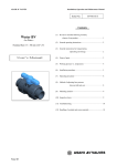
Wafer Check Valve
User’s Manual
Contents
(1) Be sure to read the following description
of our product warranty
1
(2) General operating instructions
2
(3) General instructions for transportation,
unpacking and storage
3
(4) Name of parts
4
(5) Comparison between working
temperature and pressure
5
(6) Minimum Seal performance
5
(7) Installation procedure
6
(8) Disassembling method for replacing parts
8
(9) Inspection items
9
(10) Troubleshooting
9
(11) Handling of residual and
waste materials
9
ASAHI AV VALVES
Wafer Check Valve
ASAHI AV VALVES
Installation,Operation and Maintenance Manual
This User’s Guide contains very important information for the proper installation, maintenance and safe use of
the ASAHI AV product store in an easily accessible location.
<Warning & Caution Signs>
This remark expresses the user to take caution due to the potential for serious injury or death.
Warning
Caution
This remark expresses the user to take caution due to the potential for damage to the valve if used in such
a manner.
<Prohibition & Mandatory Action Signs>
Prohibition: When operating the valve, this remark indicates an action that should not be taken.
Mandatory action: When operating the valve, this remark indicates mandatory actions that must be
adhered to.
(1)Be sure to read the following description of our product warranty.
- Always observe the specifications of and the precautions and instructions on using our product.
- We always strive to improve product quality and reliability, but cannot guarantee perfection. Therefore, should you
intend to use this product with any equipment or machinery that may pose the risk of serious or even fatal injury,
or property damage, ensure an appropriate safety design or take other measures with sufficient consideration given
to possible problems. We shall assume no responsibility for any inconvenience stemming from any action on your
part without our written consent in the form of specifications or other documented approval.
- The related technical documents, operation manuals, and other documentation prescribe precautions on
selecting, constructing, installing, operating, maintaining, and servicing our products. For details, consult with
our nearest distributor or agent.
- Our product warranty extends for one and a half years after the product is shipped from our factory or one year
after the product is installed, whichever comes first. Any product abnormality that occurs during the warranty
period or which is reported to us will be investigated immediately to identify its cause. Should our product be
deemed defective, we shall assume the responsibility to repair or replace it free of charge.
- Any repair or replacement needed after the warranty period ends shall be charged to the customer.
- The warranty does not cover the following cases:
(1) Using our product under any condition not covered by our defined scope of warranty.
(2) Failure to observe our defined precautions or instructions regarding the construction, installation,
handling, maintenance, or servicing of our product.
(3) Any inconvenience caused by any product other than ours.
(4) Remodeling or otherwise modifying our product by anyone other than us.
(5) Using any part of our product for anything other than the intended use of the product.
(6) Any abnormality that occurs due to a natural disaster, accident, or other incident not stemming
from something inside our product.
Wafer Check Valve
1
ASAHI AV VALVES
Installation,Operation and Maintenance Manual
(2) General operating instruction
Warning
Caution
- Using a positive-pressure gas with our plastic piping may pose a dangerous condition due to the
repellent force particular to compressed fluids, even when the gas is under the same pressure as water.
Therefore, be sure to take the necessary safety precautions such as covering the piping with protective
material. For inquiries, please contact us. For conducting a leak test on newly installed piping, be sure
to check for leaks under water pressure. If absolutely necessary to use gas in testing, please consult
your nearest service station beforehand.
- Do not step on the valve or apply excessive weight on valve. (It can be damaged.)
- Keep the valve away from excessive heat or fire. (It can be damaged, or destroyed.)
- Operate the valve within the pressure Vs temperature range.
(The valve can be damaged by operating beyond the allowable range.)
- Allow sufficient space for maintenance and inspection.
- Select a valve material that is compatible with the media, refer to “CHEMICAL RESISTANCE ON
ASAHI AV VALVE”. (Some chemicals may damage incompatible valve materials.)
- Do not use the valve on condition that fluid has crystallized. (The valve will not operate properly.)
- Keep the valve away from places of direct sunlight, water and dust. Use cover to shield the valve.
(The valve will not operate properly.)
- Perform periodic maintenance. (Leakage may develop due to temperature changes or changes
with time during prolonged storage, rest, or operation.)
- Use the valve at a pressure exceeding the minimum operating differential pressure.
(Check the effective head.)
- Be sure to use caution when opening the drain plug, as any fluid remaining in the pipeline
will escape from this point.
When closing the drain plug, the sealing torque should be about 5 N・m (44 lb・inch).
Wafer Check Valve
2
ASAHI AV VALVES
Installation,Operation and Maintenance Manual
(3) General instructions for transportation, unpacking and storage
- In suspending and supporting a valve, take enough care and do not stand under a suspended valve.
Warning
Caution
- The valve is not designed to handle any kind of impact. Avoid throwing or dropping the valve.
- Avoid scratching the valve with any sharp object.
- Do not pile up corrugated cardboard packages one on top of another too much.
Excessively piled-up packages may collapse.
- Avoid contact with any coal tar creosote, insecticides, vermicides or paint.
(The force of swelling may damage the valve.)
- Be sure to carry a valve as shown in the following pictures, or parts of valve may be damaged by excessive
stresses.
Correct position
Do not allow Disc to hang
Do not carry by Disc
- Keep the piping in the corrugated cardboard boxes, avoid direct sunlight, and store it indoors
(at Room Temperature). Also avoid storing it in a place which may become very hot.
(Corrugated cardboard packages become weaker as they become wet with water or other
liquid. Take enough care in storage and handling.)
- After unpacking the products, check that they are defect-free and meet the specifications.
Wafer Check Valve
3
ASAHI AV VALVES
Installation,Operation and Maintenance Manual
(4) Name of parts
Nominal size 80mm,100mm,125mm,150mm,200mm,250mm, 300mm (3”,4” 5”,,6”,8”,10”, 12”)
No.
[1]
[2]
[3]
[4]
[5]
[6]
[7]
Wafer Check Valve
DESCRIPTION
Body
Disc
Stopper
Shaft
Plug
Bolt
I Bolt
No.
DESCRIPTION
[8]
Spring *1
[9]
O-ring (A)
[10]
O-ring (B)
[11]
O-ring (C)
[12]
O-ring (D) *2
[13]
Drain Plug*2
1
* Only for spring type
*2Only for drain type
4
ASAHI AV VALVES
Installation,Operation and Maintenance Manual
(5) Comparison between working temperature and pressure
Nominal size: 250~300mm (10-12")
1.0
{10.2}
[150]
0.5
{5.1}
[70]
0.0
-40 -20
(-40) (-5)
0
(30)
(-40) (-5)
-40 -20
(30)
0
20
40
60
80
(70) (105) (140) (175)
Temperature ℃ (゚F)
(70) (105) (140) (175)
20
40
60
80
100 120
(210) (250)
Warking pressure (MPa) {kgf/cm2 } [PSI]
Warking pressure (MPa) {kgf/cm2 } [PSI]
Nominal size: 80~200mm (3-8")
1.0
{10.2}
[150]
0.5
{5.1}
[70]
0.0
(210) (250)
100 120
-40 -20
(-40) (-5)
0
(30)
(-40) (-5)
-40 -20
(30)
0
M
FK
20
40
60
80
(70) (105) (140) (175)
Temperature ℃ (゚F)
(70) (105) (140) (175)
20
40
60
80
100 120
(210) (250)
(210) (250)
100 120
M
FK
(6) Minimum seal performance (Water Pressure: at R. T.)
<Standard>
Unit: kPa {gf/cm2} [PSI]
Nominal Size
mm
Inch
80
3
Vertical Piping
Shut the Disc
Open the Disc
21.0 {210.0} [3.0]
0.7 {7.0} [0.1]
Horizontal Piping
Shut the Disc
Open the Disc
21.0 {210.0} [3.0]
0.07 {0.7} [0.01]
Unit: kPa {gf/cm2} [PSI]
Nominal Size
mm
Inch
100-300
4-12
Vertical Piping
Shut the Disc
Open the Disc
7.0 {70.0} [1.0]
0.7 {7.0} [0.1]
Horizontal Piping
Shut the Disc
Open the Disc
7.0 {70.0} [1.0]
0.07 {0.7} [0.01]
*Data mentioned in the table above is reference only.
<Spring Type>
Unit: kPa {gf/cm2} [PSI]
Nominal Size
mm
Inch
80
3
Vertical Piping
Shut the Disc
Open the Disc
21.0 {210.0} [3.0]
1.4{14..0} [0.2]
Horizontal Piping
Shut the Disc
Open the Disc
21.0 {210.0} [3.0]
0.07 {0.7} [0.01]
Unit: kPa {gf/cm2} [PSI]
Nominal Size
mm
Inch
100-300
4-12
Vertical Piping
Shut the Disc
Open the Disc
7.0 {70.0} [1.0]
1.4{14..0} [0.2]
Horizontal Piping
Shut the Disc
Open the Disc
7.0 {70.0} [1.0]
0.07 {0.7} [0.01]
*Data mentioned in the table above is reference only.
Wafer Check Valve
5
ASAHI AV VALVES
Installation,Operation and Maintenance Manual
(7) Installation procedure
- In suspending and supporting a valve, take enough care and do not stand under a suspended valve.
Warning
Caution
- Be sure to conduct a safety check on the machine tools and motor-driven tools to be used, before
beginning work.
- Wear protective gloves and safety goggles as fluid remains in the valve. (You may be injured.)
- When installing a pipe support by means of a U-band or something similar, take care not to fasten
it too much. (Excessive tension may damage it.)
- Do not use the valve for the pulsating fluid.
- Do not mount valve directly on pump outlet
- When installing pipes and valves, ensure that they are not subjected to tension, compression, bending,
impact, or other excessive stress.
- The valve is applicable to both types: vertical and horizontal piping. In the case of vertical piping, use
the valve in applications where the fluid travels upwards.
- Take care to properly install the valve by aligning flow direction arrow with intended direction of flow
Arrow
Direction flow
Direction flow
Horizontal piping
Vertical piping
- Care must be used during piping installation to ensure that the pipe inside diameter of the downstream
piping is larger than size D so that the valve disc does not contact piping in any setting.
Nominal size
80mm(3”)
100mm(4”)
125mm(5”)
150mm(6”)
200mm(8”)
250mm (10”)
300mm (12”)
Diameter D
67mm(2.64”)
100mm(3.94”)
113mm(4.45”)
146mm(5.75”)
194mm(7.64”)
241mm (9.49”)
287mm (11.3”)
- Use flat faced flanges for connection to AV Valves.
- Ensure that the mating flanges are of the same standards.
- Be sure to use bolts, nuts, and washers and tighten them to specified torques.
- The gasket is unnecessary. (The O-ring (A) carries out the role of the gasket.)
Wafer Check Valve
6
ASAHI AV VALVES
Installation,Operation and Maintenance Manual
Necessary items
● Torque wrench
● Spanner wrench
● Bolt, Nut, Washer (For many flanges specification)
Procedure
1) Install the valve between flanges after extending the fields of flanges fully.
2) Insert bolts, set nuts and washer and tighten the bolts and nuts temporarily by hand.
(When installing a valve, refer to the following picture for the detail.)
Flange
Valve
Caution
- The parallelism and axial misalignment of the flange surface should be under the values shown in the
following table to prevent damage the valve.
(A failure to observe them can cause destruction due to stress application to the pipe)
Unit : mm (inch)
(Parallelism)
(Axial misalignment)
Nom. Size
Axial
misalignment
Parallelism
(a-b)
80mm (3”)
1.0(0.04”)
0.8(0.03”)
100 , 150mm (4, 6”)
1.0(0.04”)
1.0 (0.04”)
200 - 300mm (8 - 12”)
1.5 (0.06”)
1.0 (0.04”)
3) Using a torque wrench, tighten the bolts and nuts gradually to the specified torque in a diagonal manner.
(Refer to fig.1.)
Caution
- Tighten the bolts and nuts gradually with a torque wrench to the specified torque
level in a diagonal manner.
Recommended torque value
Fig. 1
Unit: N・m{kgf・cm}[lb・inch]
Nom. Size
80,100mm (3,4”)
125,150mm (5,6”)
200,250mm (8,10”)
300mm (12”)
Torque value
30.0{306}[266]
40.0{408}[355]
55.0 {561} [488]
60.0 {612} [532]
Wafer Check Valve
7
ASAHI AV VALVES
Installation,Operation and Maintenance Manual
(8) Disassembling method for replacing parts
Warning
- Be sure to conduct a safety check on all hand and power tools to be used before beginning work.
- Wear protective gloves and safety goggles as fluid remain in the valve even if the pipeline is empty.
(You may be injured.)
- Do not change or replace valve parts under line pressure.
Necessary items
● Socket wrench (M8)
● Bolt (M6、M8)
●Allen wrench(S5、S6)
● Protective gloves
● Screw driver (-)
● Safety goggles
<Disassembly>
1) Drain the fluid completely from the pipe line.
2) Loosen the connecting bolts and nuts, and remove the valve from pipe line.
3) Nominal size80 - 200mm:Loosen the Bolt [6] by using an allen wrench, and remove the stopper [3] with spring [8]*
from the body [1].Nominal size250,300mm:Loosen the Bolt [6] by using a socket wrench, and remove the stopper [3]
with spring [8]* from the body [1].*Only for spring type
4) Loosen the plug [5] by using screw driver (-) and remove it.
5) Thrust the bolt (M8) to the threaded hole of shaft [4] and pull out the shaft [4] from the body [1].
6) Remove the Disc [2] from the body [1].
- Avoid damaging the O-ring and any other part of the valve when installing or removing the O-ring.
Caution
<Assembly>
1) The procedure of assembly is the almost reverse of its disassembly.
※Refer to the following picture for the direction of spring
Set the spring to the stopper
at 45 degree angle.
Check whether the spring
isn't distorted.
Install these parts in the order
corresponding to this.
Check whether the spring
is installed correctly.
Wafer Check Valve
Cross-section
view
8
ASAHI AV VALVES
Installation,Operation and Maintenance Manual
(9) Inspection items
Caution
- Perform periodic maintenance. (Leakage may develop due to temperature changes or changes with time
during prolonged storage, rest, or operation.)
○ Inspect the follow items ;
(1)
Check for any flaw, crack, or deformation on the outside.
(2)
Check whether fluid leaks to the outside.
(3)
Check whether tightness of bolt nut.
(10) Troubleshooting
Problem
The valve does not work.
Cause
Treatment
The disc contacts to the pipe inside Check the pipe inside diameter.
diameter.
(Refer to page 6)
Install the valve in the correct
The direction of the valve is wrong.
direction. (Refer to page 6)
Check for the minimum sealing
The minimum sealing pressure is low.
pressure. (Refer to page5)
The Fluid is leaking past the fully
O-ring is worn or damaged
Replace the O-ring. (Refer to page 8)
closed position.
Solid particles have lodged in the Remove the solid particles from the
valve.
valve and clean up the valve.
O-ring is worn or damaged
Replace the O-ring. (Refer to page 8)
Tightness of bolts and nuts.
Retighten the bolts and nuts.
Outside leakage was occurred.
(11) Handling of residual and waste materials
Warning
- Make sure to consult a waste treatment dealer to dispose of the valves.
(Poisonous gas is generated when the valve is burned improperly.)
Wafer Check Valve
9
ASAHI AV VALVES
Installation,Operation and Maintenance Manual
Wafer Check Valve
ASAHI AV VALVES
Distributor
Asahi Organic Chemicals Industry’s homepage
Information in this manual is subject to change without notice.
Wafer Check Valve
http://www.asahi-yukizai.co.jp/en/
2014.5