1
KEY FEATURES
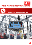
590G-V2 CT ERROR TESTER
Since 1999, Red Phase has made a revolutionary CT error
tester. This new method allowed utilities around the world to
test their CT’s in an easier and faster way than using
traditional methods without jeopardizing accuracy.
Following feedback from our users, our Model 590G-V2 CT is
the latest version of this successful and well proven CT error
tester.
This new version includes all the advantages of the previous
version with additional testing features, better accuracy and a
smaller size and weight.
Small & Lightweight (7 Kg), yet tough and durable ?
Perfect for field testing and convenient for the workshop.
Automatic, fast & fool-proof testing - Reduce testing
?
times and personnel thus lower testing costs.
Customize your tests - Not only you can use the pre
?
recorded standard tests, but you can also program 590GV2 to make your own custom made tests.
Safe testing - Simulation method allows testing at lower
?
voltage levels increasing safety.
Up to 0.1 Class CT testing - High accuracy allows
?
testing up to 0.1 class CTs.
Built in thermal printer - For on-site results printing
?
over paper or over labels (Optional).
Big 6” screen - Easily see the results in any light
?
condition.
Inbuilt memory - Store up to 300 test results and
?
download them to your computer or to a USB memory
stick.
Four terminal test leads - for superior testing
?
accuracy.
Automatic CT demagnetizing after testing .
?
In a world where cost control is gaining importance, this CT
tester not only lowers testing costs by being simple, fool-proof
and fast. It also allows utilities to pursue the very important
(yet many times forgotten) task of testing installed CT’s for
detecting tampering, and minimizing losses due to faulty
CT’s.
TEST CAPABILITIES
CT ratio and phase error measurements. (Analyses
?
if CT complies with regulations)
CT 1.6 kHz Admittance test. (Helps to determine if CT
?
is faulty i.e. a shorted turn)
CT excitation curve & knee point test. (Traditional
?
CT test)
Burden Test. (Helps to check if the burden connected to
?
the CT is higher than its rated burden)
CT winding resistance measurements
?
CT polarity measurements
?
CT live testing (With 590F accessory)
?
PT full load simulated tests (In combination with
?
model 590D)
STANDARDS COMPLIANCE
590G-V2 will test CTs and comment whether they are
complying with International Standards. Furthermore, you
can input your own standards/regulation requirements and
590G-V2 will make intelligent comments regarding them.
Some of the pre-recorded Standard verifications are (but not
limited to):
IEEE C57.13-1993 Requirements for Instrument
?
Transformers
IEC 60044 Instrument Transformers
?
CT RATIO & PHASE
ERROR TEST
1.6 KHZ ADMITTANCE
TEST
Making sure that the CT accuracy is within the standard
limits is key not only to maximize revenue but also in
many places to comply with government regulations and
avoid fines.
The 1.6 kHz admittance of a CT is quite close to the 50 Hz
admittance, and it can give a good indication of the
inherent error of a CT. It is also an important as it is
considered a “blueprint” of the CT.
The most important measurement is the turns ratio,
since that typically accounts for 99.5% of the CT ratio
accuracy. For that reason the 590G-V2 measures turns
ratio within 0.02% for nearly all common CT ratios. The
remaining 0.5% of accuracy, and all the phase error, is
accounted for by the 50Hz or 60Hz admittance (inherent
error) of the CT core. The accuracy of admittance
measurement is not so critical.
Once known, the 1.6kHz admittance of a specific CT can
be used in future to check a CT during routine meter tests
(even without supply interruption using Red Phase
Instruments model 505B live admittance tester). It is
quick and easy and any loss of revenue due to faults or
tampering with the CT is made obvious.
The following graph shows ratio error curves for a
2000/5 class 0.5 CT with exact turns ratio, at various
burden values. The error is due only to admittance. In
practice the CT will have turns compensation ( the
secondary turns ratio could be 399/1 instead of 400/1 )
which boosts the current output by 0.25% and makes the
error curve fit within the 0.5% limits.
Error
+0.5%
100%
Percentage of Rated Current
200%
-0.5%
30VA
20VA
10VA
0VA
590G-V2 automatically tests the 1.6 kHz admittance of
the CT secondary. This can be recorded or compared
with a previous measurement of the same CT or with the
admittance of similar CTs installed in the system.
BURDEN TEST
As shown in the graph, if the VA burden connected to the
CT is large it can cause large ratio errors and revenue will
be lost. This is usually more of a problem with low VA
rated CTs, say in the 5VA to 15VA range. The 590G-V2 can
quickly measure the burden and make sure it does not
exceed the rating.
Once you have the real burden value for the CT, you
can also opt to perform a error test to see what errors
the CT has at exactly that burden.
BURDEN TEST CONNECTIONS
Note that the CT accuracy varies not only with the
connected burden, but also with the % of rated current
circulating through its primary. Generally the CT ratio
and phase errors are calculated at 5%; 20%; 100% and
120% primary rated current and 25% and 100% rated
burden. These test points can easily be changed to suit
any utility need or government regulation.
With traditional primary injection, testing can take over
30 minutes for 10 CT test points. The 590G-V2 will do this
automatically in around 5 minutes.
P
S
Zb
CT
LIVE RATIO TEST
Combined with the Model 590F accessory, the 590G-V2
performs a live ratio and phase error test with customer
load, on either LV CTs or HV CTs. The 590F uses
electronically compensated clipons, and fibre optic
connection for HV CTs.
Both LV & HV kits are available, The kit includes a 100m
fibre optic cable drum for testing in locations where the
HV CT primary is not close to the secondary test point.
590F accessory is the perfect solution for fast CT testing
where customer supply interruption is not an option.
POLARITY MEASUREMENTS
590G-V2 will automatically report if there is a polarity
error in the CT.
This error could be caused either incorrect marking by CT
manufacturer or incorrect installation.
EXCITATION CURVE TEST
This is a very traditional test for CTs. Although not strictly
needed after the 590G-V2 tests at the usual 10 test
points to make sure the CT error is within limits when
connected to a burden within its rating, many utilities
still like to see an excitation curve.
The 590G-V2 will display and/or print (with the optional
printer accessory) the excitation curve of the CT and will
give the knee point according to any of the three knee
point methods:
1) A 10% increase in the exciting voltage results in a 50%
increase in exciting current
2) The 35° tangent point.
3) The 45° tangent point.
BACKGROUND
INCLUDED ACCESSORIES
In an era where costs, revenues and service levels are every
day more important for utilities worldwide, a low cost method
to deal with CT metering errors caused either by tampering or
equipment failure is an important part of the equation.
Foam Lined transit case for protection in transport.
?
Testing CTs should be a crucial part of utility monitoring. In
general utilities make in-field meter tests (especially when
meter readings are suspected) and forget to test the CTs
related to those meters, which are as important as the meters.
OPTIONAL ACCESSORIES
6 m Testing leads with banana plugs.
?
Crocodile clamps for primary and secondary connections.
?
User manual
?
Thermal Printer.
?
590G-V2 Calibration/Reference CT
?
Traditional CT testing (primary injection) has many
disadvantages. Not only is the equipment bulky, heavy,
expensive and difficult to use, it is a time consuming method.
More than 10 years ago Red Phase Instruments designed the
first series of Model 590 to make a major improvement in field
testing CTs. With the feedback we got from our worldwide
customers and following our continuous improvement
search, this product evolved (adding new features and
improving existing ones) into this latest version.
Red Phase Instruments 590G-V2 is the perfect solution for
utilities looking to improve revenues and service quality and
at the same time lower costs. This state of the art yet proven
CT testing system is small, light, durable, robust, easy and fast
to use with a minimum personnel.
CONNECTIONS
CT
S
P
Custom Length test leads.
?
COMPLEMENTARY PRODUCTS
590F performs live CT ratio test
when connected to 590G-V2.
Battery operated with microprocessor
compensation to use over a wide
operating range of CTs, Typically from
50A to 1500A.
Supplied with a 100m fiber optic cable.
590D1
performs full load
inductive PT (VT) tests when
connected to 590G-V2.
Built with a high power switch mode
source for full load performance
testing under simulated conditions to
0.1% accuracy.
Uses 590G microprocessor for testing
but includes own microprocessor for
monitoring & control.
505B
performs live 1.6kHz
admittance tests without interruption
of the customer’s service.
It is a quick and simple way of checking
Cts during a routine kWh meter test.
TECHNICAL DATASHEET
CT ratio measurement (Turns ratio of secondary to
primary winding)
CT Measurement accuracy
Ratios 0.5/1 (2.5/5) up to 4.000/1 (20.000/5)
0.02%
Ratios 4.000/1 (20.000/5) up to 15.000/1 (75.000/5)
CT Ratio error test accuracy
0.03%
Currents between 5% and 120% rated value
CT Phase error test accuracy
0.02%
Currents between 5% and 120% rated value
PT (VT) Measurement accuracy
1 min
Ratios 1.5kV/100V up to 500kV/110V
0.02%
Ratios 500kV/110V up to 1000kV/110V
0.03%
Winding Resitance Accuracy
0.2 % + 1 m?
External Burden accuracy
0.2 % + 1 m?
1.6 kHz Admittance accuracy
0.5 % + 100 ìS
Magnetising Curve Knee Point
3 methods (10%-50%; IEEE-30; IEEE-45)
Input Power
Subject to change without notice
up to 99.000 /1
100 V to 250 V (50 Hz or 60 Hz) or 12V car batery
Standby 20 VA
Testing 50 VA
Display
15 cm (6") Readable in bright and low light conditions
Records Storage
Internal memory (stores more than 3.000 records)
PC transfer
USB port
Size
410 x 330 x 180 mm (16" x 13 " x 7 ")
Weight (Without accessories or test leads)
7 kg (15.4 lb)
RED PHASE INSTRUMENTS has been providing instrument and
testing solutions for the worldwide electric power industry for more than 35 years.
From our headquarters in Melbourne, Australia, we design and manufacture state of the
art equipment that often no other company makes. We also manufacture and service
older an more mature products that are still in demand.
Our customers vary from the very largest national utilities to small pacific island
cooperatives with only 10MW capacity.
No matter who our customers are, we plan to give them excellent service and products
helping them to achieve the maximum result at a reasonable price.
Red Phase Instruments Pty Ltd.
10 Ceylon St,
Nunawading (3131),
Melbourne,
VIC, Australia.
[email protected]
www.redphase.com.au
Distributed By: