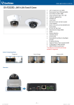
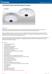
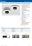
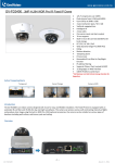
1
GV-Mount Accessories Installation Guide Before attempting to connect or operate this product, please read these instructions carefully and save this manual for future use. MT-D © 2013 GeoVision, Inc. All rights reserved. Under the copyright laws, this manual may not be copied, in whole or in part, without the written consent of GeoVision. Every effort has been made to ensure that the information in this manual is accurate. GeoVision, Inc. makes no expressed or implied warranty of any kind and assumes no responsibility for errors or omissions. No liability is assumed for incidental or consequential damages arising from the use of the information or products contained herein. Features and specifications are subject to change without notice. GeoVision, Inc. 9F, No. 246, Sec. 1, Neihu Rd., Neihu District, Taipei, Taiwan Tel: +886-2-8797-8377 Fax: +886-2-8797-8335 http://www.geovision.com.tw Trademarks used in this manual: GeoVision, the GeoVision logo and GV series products are trademarks of GeoVision, Inc. Windows and Windows XP are registered trademarks of Microsoft Corporation. August 2013 Contents Contents ...................................................................................................................... i Installation Overview ................................................................................................ iv Required Accessories ............................................................................................. vii Note for Installing Camera Outdoor ......................................................................... x 1. Introduction........................................................................................................... 1 1.1 Accessories List ......................................................................................................................... 1 1.2 Dimensions ................................................................................................................................ 8 1.3 Packing Lists ........................................................................................................................... 12 2. Installing the Vandal Proof IP Dome ................................................................. 21 2.1 Assembling the Vandal Proof IP Dome with the dome housing .............................................. 21 2.3 Straight Tube Mount ................................................................................................................ 27 2.4 L-Shaped Wall Mount .............................................................................................................. 30 2.5 Wall Pendant Mount ................................................................................................................ 33 2.6 Convex Corner Mount with Pendant Tube .............................................................................. 35 2.7 Convex Corner Mount with Wall Bracket................................................................................. 37 2.8 Convex Corner Box Mount ...................................................................................................... 41 2.9 Concave Corner Mount with Pendant Tube ............................................................................ 45 2.10 Concave Corner Mount with Wall Bracket............................................................................. 47 2.11 Pole Mount with Pendant Tube ............................................................................................. 50 2.12 Pole Mount with Wall Bracket ................................................................................................ 53 2.13 Pole Box Mount ..................................................................................................................... 56 3. Installing the Fixed IP Dome .............................................................................. 59 3.1 Basic Installation ....................................................................................................................... 59 3.1.1 Assembling the Fixed IP Dome with the Dome Housing .................................................................................... 59 3.1.2 Putting on the Housing Cover ............................................................................................................................ 61 3.2 Straight Tube Box Mount ......................................................................................................... 62 3.3 Straight Tube Mount ................................................................................................................ 66 3.4 L-Shaped Wall Mount .............................................................................................................. 69 3.5 Wall Pendant Mount ................................................................................................................ 71 i 3.6 Convex Corner Mount ............................................................................................................. 73 3.7 Convex Corner Box Mount ...................................................................................................... 75 3.8 Concave Corner Mount ........................................................................................................... 79 3.9 Pole Mount .............................................................................................................................. 81 3.10 Pole Box Mount ..................................................................................................................... 83 4. Installing the Fisheye Camera ........................................................................... 87 4.1 Assembling the Fisheye Camera with the Dome Housing ...................................................... 87 4.2 Straight Tube Box Mount ......................................................................................................... 89 4.3 Straight Tube Mount ................................................................................................................ 93 4.4 Wall Pendant Mount ................................................................................................................. 95 4.5 Tilting Wall Mount .................................................................................................................... 96 4.6 Convex Corner Mount ............................................................................................................. 99 4.7 Convex Corner Box Mount .................................................................................................... 101 4.8 Concave Corner Mount ......................................................................................................... 104 4.9 Pole Mount ............................................................................................................................ 106 4.10 Pole Box Mount ................................................................................................................... 108 5. Installing the GV-SD220/220-S IP Speed Dome .............................................. 111 5.1 Assembling GV-SD220-S with Pendant Tube ....................................................................... 111 5.2 GV-SD220 In-Ceiling Mount .................................................................................................. 113 5.3 GV-SD220-S In-Ceiling Mount .............................................................................................. 117 5.4 Straight Tube Box Mount ....................................................................................................... 120 5.5 Straight Tube Mount .............................................................................................................. 123 5.6 Convex Corner Mount ........................................................................................................... 126 5.7 Convex Corner Box Mount .................................................................................................... 127 5.9 Pole Mount ............................................................................................................................ 131 5.10 Pole Box Mount ................................................................................................................... 132 6. Installing the Bullet Camera ............................................................................ 134 6.1 Convex Corner Mount ........................................................................................................... 134 6.2 Concave Corner Mount ......................................................................................................... 136 6.3 Pole Mount ............................................................................................................................ 138 7. Installing the Arctic Box Camera .................................................................... 140 7.1 Convex Corner Mount ........................................................................................................... 140 ii 7.2 Concave Corner Mount ......................................................................................................... 142 7.3 Pole Mount ............................................................................................................................ 144 iii Installation Overview Vandal Proof IP Dome Fixed IP Dome Fisheye Camera GV-SD220 or GV-SD220-S Bullet Camera Arctic Box Camera Standard Installation Ceiling Hard Ceiling *GV-SD220 only In-Ceiling Wall Wall-Surface Wall Mount Wall Pendant *GV-SD220-S only Ground Ground Mount Optional Installation Wall L-Shaped Wall Mount L-Shaped Wall Mount Tilting Wall Mount Wall Pendant Mount iv Wall Mount Wall Mount Vandal Proof IP Dome Fixed IP Dome Fisheye Camera GV-SD220 or GV-SD220-S Bullet Camera Arctic Box Camera Optional Installation Ceiling In-Ceiling Mount *GV-SD220 only *GV-SD220-S only Straight Tube *GV-SD220-S only Straight Tube Box *GV-SD220-S only Corner Convex Corner Mount *GV-SD220-S only Convex Corner Box Mount *GV-SD220-S only v Vandal Proof IP Dome Fixed IP Dome Fisheye Camera GV-SD220 or GV-SD220-S Optional Installation Corner Concave Corner Mount *GV-SD220-S only Pole Pole Mount *GV-SD220-S only Pole Box Mount *GV-SD220-S only vi Bullet Camera Arctic Box Camera Required Accessories A variety of installation methods are designed for GV-Vandal Proof IP Dome, GV-Fixed IP Dome, GV-Fisheye Camera, outdoor GV-IP Speed Dome, GV-Bullet Camera and GVArctic Box Camera to be installed in different environments. Look up the required accessories from the table below. Contact your local dealer for more information. Optional Installation Method Required Optional Accessories Ceiling Mount Straight Tube Box Mount Straight Tube Mount In-Ceiling Mount GV-FD Series GV-Mount100 + GV-Mount902 GV-FE Series GV-Mount100 + GV-Mount903 GV-SD220-S GV-Mount100 GV-VD Series GV-Mount100 + GV-Mount901 GV-FD Series GV-Mount101 + GV-Mount902 GV-FE Series GV-Mount101 + GV-Mount903 GV-SD220-S GV-Mount101 GV-VD Series GV-Mount101 + GV-Mount901 GV-SD220 GV-Mount907 GV-SD220-S GV-Mount908 GV-FD Series GV-Mount900 for GV-FD Series GV-VD Series GV-Mount900 for GV-VD Series GV-FD Series GV-Mount200 + GV-Mount902 GV-FE Series GV-Mount200 + GV-Mount903 GV-VD Series GV-Mount200 + GV-Mount901 GV-FE Series GV-Mount904 GV-BL Series GV-Mount300 GV-BX-E Series GV-Mount300 GV-FD Series GV-Mount300 + GV-Mount200 + GV-Mount902 GV-FE Series GV-Mount300 + GV-Mount200 + GV-Mount903 GV-SD220-S GV-Mount300 + GV-Mount200 Wall Mount L-Shaped Wall Mount Wall Pendant Mount Tilting Wall Mount Corner Mount Convex Corner Mount GV-VD Series Convex Corner Box Mount GV-Mount300 + GV-Mount900 GV-Mount300 + GV-Mount200 + GV-Mount901 GV-FD Series GV-Mount300 + GV-Mount203 + GV-Mount902 GV-FE Series GV-Mount300 + GV-Mount203 + GV-Mount903 GV-SD220-S GV-Mount300 + GV-Mount203 GV-VD Series GV-Mount300 + GV-Mount203 + GV-Mount901 vii Installation Method Accessories Required Corner Mount Concave Corner Mount GV-BL Series GV-Mount310 GV-BX-E Series GV-Mount310 GV-FD Series GV-Mount310 + GV-Mount200 + GV-Mount902 GV-FE Series GV-Mount310 + GV-Mount200 + GV-Mount903 GV-SD220-S GV-Mount310 + GV-Mount200 GV-Mount310 + GV-Mount900 GV-VD Series Ø 4’’ ~ 6’’ GV-Mount310 + GV-Mount200 + GV-Mount901 GV-BL Series GV-Mount400 GV-BX-E Series GV-Mount400 GV-FD Series GV-Mount400 + GV-Mount200 + GV-Mount902 GV-FE Series GV-Mount400 + GV-Mount200 + GV-Mount903 GV-SD220-S GV-Mount400 + GV-Mount200 GV-Mount400 + GV-Mount900 GV-VD Series GV-Mount400 + GV-Mount200 + GV-Mount901 Pole Mount Ø 6’’ ~ 7.5’’ GV-BL Series GV-Mount410 GV-BX-E Series GV-Mount410 GV-FD Series GV-Mount410 + GV-Mount200 + GV-Mount902 GV-FE Series GV-Mount410 + GV-Mount200 + GV-Mount903 GV-SD220-S GV-Mount410 + GV-Mount200 GV-Mount410 +GV-Mount900 GV-VD Series Ø 4’’ ~ 6’’ Pole Box Mount GV-Mount410 + GV-Mount200 + GV-Mount901 GV-FD Series GV-Mount400 + GV-Mount203 + GV-Mount902 GV-FE Series GV-Mount400 + GV-Mount203 + GV-Mount903 GV-SD220-S GV-Mount400 + GV-Mount203 GV-VD Series GV-Mount400 + GV-Mount203 + GV-Mount901 GV-FD Series GV-Mount410 + GV-Mount203 + GV-Mount902 GV-FE Series GV-Mount410 + GV-Mount203 + GV-Mount903 GV-SD220-S GV-Mount410 + GV-Mount203 GV-VD Series GV-Mount410 + GV-Mount203 + GV-Mount901 Ø 6’’ ~ 7.5’’ viii IMPORTANT: 1. For Straight Tube Box Mount, Convex Corner Box Mount, Concave Corner Box Mount and Pole Box Mount, a user-prepared corrugated tube of 3/4’’, ø 26.0 ~ 26.5 mm is required. For example, 2. To extend the tube for Straight Tube Box Mount and Straight Tube Mount, purchase a GV-Mount702. ix Note for Installing Camera Outdoor When installing the camera outdoor, be sure that: 1. The camera is set up above the junction box to prevent water from entering the camera along the cables. 2. Any PoE, power, audio and I/O cables are waterproofed using waterproof silicon rubber or the like. 3. After opening the camera cover, ensure the screws are tightened and the cover is in place. 4. To prevent the lens from fogging up, ensure to replace the silica gel bag/desiccant pack every time you open the camera, and conceal the gel bag/desiccant pack in the camera within 2 minutes of exposing to open air. The silica gel bag/desiccant loses it effectiveness when the dry camera is opened. x 1 Introduction 1. Introduction 1.1 Accessories List Model No. Name Details GV-Mount100 Straight Tube and Junction Box Kit Dimensions 200 x 170 x 257.5 mm / 7.9 x 6.7 x 10.1 in Weight 3.17 Kg / 6.99 lbs Supplied with M5 flat screw (15 mm) x 4 Corrugated tube connector x 1 No.2 torx wrench x 1 GV-Mount101 Straight Tube Kit Dimensions 219 x 125 x 332 mm / 8.6 x 4.9 x 13.1 in Weight 1.8 Kg / 3.97 lbs Supplied with No.2 torx wrench x 1 GV-Mount200 Wall Pendant Tube Dimensions (L x W x D) 200 x 140 x 254 mm / 7.9 x 5.5 x 10.0 in Weight: 0.93 Kg / 2.05 lbs 1 Model No. Name Details GV-Mount203 Wall Pendant Tube and Junction Box Kit Dimensions 315 x 195.5 x 225 mm / 12.4 x 7.7 x 8.9 in Weight 2.95 Kg / 6.5 lbs Supplied with M5 screw (25 mm) x 2 Corrugated tube connector x 1 No.5 Torx Wrench x 1 GV-Mount300 Convex Corner Adapter Kit Dimensions 238.6 x 409.5 mm / 9.4 x 16.1 in Weight 4.27 Kg / 9.41 lbs Option 1 Supplied with: M8 screw (30 mm) x 4 M8 screw cap x 6 M8 split washer x 6 M8 plain washer x 6 M5 screw (20 mm) x 3 M5 screw cap x 3 M5 split washer x 3 M5 plain washer x 3 Option 2 Supplied With: M8 screw (25 mm) x 4 M8 screw cap x 6 M8 split washer x 6 M8 plain washer x 6 M5 screw (25 mm) x 2 M5 screw (20 mm) x 3 M5 screw cap x 3 M5 split washer x 3 M5 plain washer x 3 2 1 Introduction Model No. Name Details GV-Mount310 Concave Corner Adapter Kit Dimensions 123.3 x 393.1 mm / 4.9 x 15.5 in Weight 2.96 Kg / 6.53 lbs Supplied with M8 screw (30 mm) x 4 M8 screw cap x 6 M8 split washer x 6 M8 plain washer x 6 M5 screw (20 mm) x 3 M5 screw cap x 3 M5 split washer x 3 M5 plain washer x 3 GV-Mount400 Pole Mount Bracket Kit (Ø 4’’ ~ 6’’) Dimensions (Bracket) Bracket: 241 x 161 mm / 9.5 x 6.3 Steel Strap Diameter Ø 4’’ ~ 6’’ Weight 1.70 Kg / 3.75 lbs Supplied with Stainless steel strap (Ø 4’’ ~ 6’’) x 3 M8 screw (30 mm) x 4 M8 screw (25 mm) x 4 M8 screw cap x 4 M8 split washer x 4 M8 plain washer x 4 M5 screw (20 mm) x 3 M5 screw cap x 3 M5 split washer x 3 M5 plain washer x 3 3 Model No. Name Details GV-Mount410 Pole Mount Bracket Kit (Ø 6’’ ~ 7.5’’) Dimensions (Bracket) 241 x 161 mm / 9.5 x 6.3 in Steel Strap Diameter Ø 6’’ ~ 7.5’’ Weight 1.70 Kg / 3.75 lbs Supplied with Stainless steel strap (Ø 6’’ ~ 7.5’’) x 3 M8 screw (30 mm) x 4 M8 screw (25 mm) x 4 M8 screw cap x 4 M8 split washer x 4 M8 plain washer x 4 M5 screw (20 mm) x 3 M5 screw cap x 3 M5 split washer x 3 M5 plain washer x 3 GV-Mount702 Extension Tube Four options are available. Dimensions Ø 5.4 x 10 or 20 or 30 or 50 cm Ø 2.1 x 3.9 / 7.9 / 11.8 / 19.7 in Weight 180 g / 0.4 lbs 390 g / 0.86 lbs 550 g / 1.21lbs 800 g / 1.76 lbs Supplied with Extension tube connector x 1 4 1 Introduction Model No. Name Details GV-Mount900 Wall Mount Bracket For L-shaped wall mount of Vandal Proof IP Dome and Fixed IP Dome. Dimensions 154 x 108 x 50 mm / 6.1 x 4.3 x 2 in Supplied with (GV-VD Series) Short screw x 4 Screw cap x 4 Supplied with (GV-VD Series) Long screw anchor x 2 Wall mount screw x 2 Short screw x 3 GV-Mount901 GV-VD Series Dome Housing Dimensions ø 186 x 97.5 mm / ø 7.3 x 3.8 in Weight: 600 g / 1.32 lb Supplied with M4 screw x 4 M6 screw x 7 GV-Mount902 GV-FD Series Dome Housing Dimensions ø 186 x 97.5 mm / ø 7.3 x 3.8 in Weight 600 g / 1.32 lb Supplied with Left & right rack x 1 (pair) Housing plate x 1 Small screw x 3 M4 screw x 4 M6 screw x 7 5 Model No. Name Details GV-Mount903 Fisheye Dome Housing Dimensions ø 185.51 x 150.35 mm / 7.3 x 5.9 in Weight 700 g / 1.54 lb Supplied with M4 screw x 4 M6 screw x 7 GV-Mount904 Tilting Wall Mount Bracket Dimension ø 159.1 x 40.5 mm / ø 6.3 x 1.6 in Tilt angle: 0-20 ° Supplied with Back cover x 1 Back plate x 1 Tilting rack x 1 Long screw x 3 Short screw x 9 Installation sticker x 1 GV-PA191 Power over Ethernet (PoE) Adapter The GV-PA191 is a Power over Ethernet (PoE) adapter designed to provide power to the IP device through a single Ethernet cable. For details, see http://www.geovision.com.tw/eng lish/Prod_GVPA191.asp 6 1 Introduction Model No. Name Details GV-Mount907 In-Ceiling Mounting Kit for GV-SD220 IP Speed Dome Dimension Ø 230 x 153.49 mm / Ø 9.08 x 6.05 in Weight 0.87 kg / 1.91 lb Supplied with In-ceiling cover x 1 Mounting ring x 1 Mounting plate x 1 Support rack x 3 Screw x 9 Thread lock & screw x 1 set Lock plate & screw x 1 set Hex key x 1 GV-Mount908 In-Ceiling Mounting Kit for GV-SD220-S IP Speed Dome Dimension Mounting plate: 227 x 286 mm Weight 2.05 Kg / 4.5 lb Supplied with Screw x 4 Hex key x 1 M6 screw x 4 Installation sticker x 1 M4 screw x 2 In-ceiling cover x 1 7 1.2 Dimensions • GV-Mount100 • GV-Mount101 8 1 • GV-Mount200 • GV-Mount203 Introduction 9 • GV-Mount300 108 35 210 165 42 42 5 40 85 9 .5 • 80 GV-Mount310 42 5 200 165 108 40 35 9 .5 9.5 85 40 10 80 9. 5 1 • Introduction GV-Mount400/Mount410 37,5 314 163 20 88 40 42 5 9. 85 80 • 81 37,5 9.5 68,5 35 165 240 5 163 9. 5 GV-Mount908 11 1.3 Packing Lists • GV-Mount100 1. Junction Box 2. Box Cover 3. Tube 4. Tube Connector 5. M5 Flat Screw x 4 6. Corrugated Tube Connector 7. No. 2 Torx Wrench • 12 GV-Mount101 1. Mounting Bracket 2. Tube 3. Tube Connector 4. No. 2 Torx Wrench 1 • Introduction GV-Mount200 1. Wall Pendant Tube • GV-Mount203 1. Junction Box 2. Wall Pendant Tube 3. M5 Screw x 2 4. Corrugated Tube Connector 5. No.5 Torx Wrench • GV-Mount300 1. Mounting Plate x 2 2. M8 Screw (30 mm) x 4 3. M8 Screw (25 mm) x 4 4. M8 Plain Washer x 6 5. M8 Split Washer x 6 6. M8 Screw Cap x 6 13 • 7. M5 Screw (20 mm) x 3 8. M5 Plain Washer x 3 9. M5 Split Washer x 3 10. M5 Screw Cap x 3 GV-Mount310 1. Mounting Plate x 2 2. M8 Screw (30 mm) x 4 3. M8 Plain Washer x 6 4. M8 Split Washer x 6 5. M8 Screw Cap x 6 6. M5 Screw (20 mm) x 3 7. M5 Plain Washer x 3 8. M5 Split Washer x 3 9. M5 Screw Cap x 3 • GV-Mount400 1. Mounting Bracket 14 2. Stainless Steel Strap (Ø 4’’ ~ 6’’) x 3 1 3. M8 Screw (30 mm) x 4 4. M8 Screw (25 mm) x 4 5. Plain Washer x 4 6. Split Washer x 4 7. M8 Screw Cap x 4 8. M5 Screw (20 mm) x 3 9. M5 Plain Washer x 3 10. M5 Split Washer x 3 Introduction 11. M5 Screw Cap x 3 • GV-Mount410 1. Mounting Bracket 2. Stainless Steel Strap (Ø 6’’ ~ 7.5’’) x 3 3. M8 Screw (30 mm) x 4 4. M8 Screw (25 mm) x 4 5. Plain Washer x 4 6. Split Washer x 4 7. M8 Screw Cap x 4 8. M5 Screw (20 mm) x 3 9. M5 Plain Washer x 3 10. M5 Split Washer x 3 11. M5 Screw Cap x 3 15 • GV-Mount702 1. Extension Tube • 2. Extension Tube Connector GV-Mount900 for Vandal Proof IP Dome 1. Wall Mount Bracket 2. Short Screw x 4 3. Screw Cap x 4 • 16 GV-Mount900 for Fixed IP Dome 1. Wall Mount Bracket 2. Long Screw Anchor x 2 3. Wall Mount Screw x 2 4. Short Screw x 3 1 • • Introduction GV-Mount901 for Vandal Proof IP Dome 1. Dome Housing 2. Housing Cap 3. M4 Screw x 4 4. M6 Screw x 7 GV-Mount902 for Fixed IP Dome 1. Dome Housing 2. Housing Cap 3. M4 Screw x 4 4. M6 Screw x 7 5. Left and Right Rack 6. Housing Plate 7. Small Screw x 3 • GV-Mount903 for Fisheye Camera 17 • 1. Dome Housing 2. Housing Cap 3. M4 Screw x 4 4. M6 Screw x 7 GV-Mount904 1. Back Cover 2. Back Plate 3. Tilting Rack 4. Long Screw x 3 5. Short Screw x 9 6. Installation Sticker 18 1 • Introduction GV-Mount907 1. Support Rack x 3 2. Mounting Ring 3. Screw x 9 4. Thread Lock, Screw, Washer 5. Mounting Plate x 1 6. Hex Key 7. Lock Plate and Screw 8. Installation Sticker 9. In-Ceiling Cover 19 • 20 GV-Mount908 1. Housing Cap x 1 2. Mounting Plate x 1 3. Screw x 4 4. M6 Screw x 4 5. Hex key x 1 6. Installation Sticker x 1 7. In-ceiling cover x 1 8. M4 Screw x 2 2. Installing the Vandal Proof IP Dome 2.1 Assembling the Vandal Proof IP Dome with the dome housing Required accessories: GV-Mount901 1. Unpack the camera body. A. B. C. D. 2. Secure the back cover to the dome housing (GV-Mount901, No. 1) with M4 screws (GVMount901, No. 3). 3. Thread the camera cable through the back cover and the dome housing. 4. Align the camera body so that the protruding part of the back cover fits the camera body and secure them together. 5. Thread the cable through the housing cap (GV-Mount901, No. 2) and secure with M6 screws (GV-Mount901, No. 4). 22 2 Installing the Vandal Proof IP Dome 2.2 Straight Tube Box Mount Required accessories: GV-Mount100 GV-Mount901 The user needs to prepare: Screws for ceiling x 4 Corrugated tube x 1 (3/4’’, ø 26.0 ~ 26.5 mm) Optionally extend with: GV-Mount702 23 1. Assemble the camera to the dome housing. See 2.1 Assembling the Vandal Proof IP Dome with the Dome Housing. 2. Assemble the tube (GV-Mount100, No. 3) and the tube connector (GV-Mount100, No. 4). 3. Thread the camera cable through the tube and secure the tube to the end of the housing cap (GV-Mount901, No. 2) with M6 screws (GV-Mount901, No. 4). 4. Thread the camera cable through the box cover (GV-Mount100, No. 2), assemble the box cover and the tube, and tighten the torxes using the torx wrench (GV-Mount100, No. 7). 24 2 Installing the Vandal Proof IP Dome 5. Secure the junction box (GV-Mount100, No. 1) to the ceiling with 4 self-prepared screws. 6. Assemble the corrugated tube connector (GV-Mount100, No. 6) with the self-prepared corrugated tube. A. Dismantle the supplied corrugated tube connector. You should have 4 parts. A B C D B. Slide part A and part B to the self-prepared corrugated tube. A+B C D C. Screw part C to the tube. D. Thread the necessary wires and cables from the ceiling through the corrugated tube, plug the tube to the junction box and secure with part D. Ethernet Power 7. Connect the network, power and other cables to the camera. See 10.5 Connecting the Camera, GV-IPCam H.264 User’s Manual on the software CD. 25 8. Hook the box cover and secure it with M5 flat screws (GV-Mount100, No. 5). Ethernet Power 9. Refer to the indicated sections of the GV-IPCam H.264 User’s Manual on the software CD to: A. Access live view. See 14.1 Accessing the Live View. B. Adjust the angle, focus and zoom of the camera. See steps 9 and 10 in 10.4.1 HardCeiling Mount. C. Secure the thread lock, replace the silica gel bag and secure the housing cover. See steps 11 to 13 in 10.4.1 Hard-Ceiling Mount. 26 2 Installing the Vandal Proof IP Dome 2.3 Straight Tube Mount Required accessories: GV-Mount101 GV-Mount901 The user needs to prepare: Screws for ceiling x 4 Optionally extend with: GV-Mount702 27 1. Assemble the camera with the dome housing. See 2.1 Assembling the Vandal Proof IP Dome with the Dome Housing. 2. Assemble the tube (GV-Mount101, No. 2) and the tube connector (GV-Mount101, No. 3). 3. Thread the camera cable through the tube and assemble the tube to the end of the housing cap (GV-Mount901, No. 2) with M6 screws (GV-Mount901, No. 4). 4. Thread the camera cable through the mounting bracket (GV-Mount101, No. 1) and assemble the tube with the mounting bracket. 5. Make sure the tubes are properly screwed and tighten with the supplied torx wrench (GVMount101, No. 4). 6. Secure the assembled camera to a desired location with 4 self-prepared screws. 28 2 Installing the Vandal Proof IP Dome 7. Refer to the indicated sections of the GV-IPCam H.264 User’s Manual on the software CD to: A. Connect the network, power and other cables to the camera. See 10.5 Connecting the Camera. B. Access live view. See 14.1 Accessing the Live View. C. Adjust the angle, focus and zoom of the camera. See steps 9 and 10 in 10.4.1 HardCeiling Mount. D. Secure the thread lock, replace the silica gel bag and secure the housing cover. See steps 11 to 13 in 10.4.1 Hard-Ceiling Mount. 29 2.4 L-Shaped Wall Mount Required accessories: GV-Mount900 1. Take the wall mount bracket (GV-Mount900 for GV-VD Series, No. 1) and make 2 marks on the wall for screw anchors. wall 2. Drill the marks and insert 2 screw anchors. 3. Insert the ceiling screws and leave enough distance (approximately 2 mm) to hang the wall mount bracket later. 2 mm Long Screw Wall 30 2 Installing the Vandal Proof IP Dome 4. Hang the wall mount bracket on the ceiling screws and push the wall mount bracket downward. Tighten the screws to the wall. 5. Unpack the camera body. A. B. C. D. 6. Secure the back cover to the wall mount bracket with four short screws (GV-Mount900 for GV-VD Series, No. 2) and screw caps (GV-Mount900 for GV-VD Series, No. 3). 31 7. Thread the cable through the conduit entry at the bottom of the back cover and follow steps 5 to re-assemble the camera. 8. Refer to the indicated sections of the GV-IPCam H.264 User’s Manual on the software CD to: A. Connect the network, power and other cables to the camera. See 10.5 Connecting the Camera. B. Access live view. See 14.1 Accessing the Live View. C. Adjust the angle, focus and zoom. See steps 9 and 10 in 10.4.1 Hard-Ceiling Mount. D. Secure the thread lock, replace the silica gel bag and secure the housing cover. See steps 11 to 13 in 10.4.1 Hard-Ceiling Mount. 32 2 Installing the Vandal Proof IP Dome 2.5 Wall Pendant Mount Required accessories: GV-Mount200 GV-Mount901 The user needs to prepare: Screws for wall x 4 1. Assemble the camera with the dome housing. See 2.1 Assembling the Vandal Proof IP Dome with the Dome Housing. 2. Thread the camera cable through the wall pendant tube (GV-Mount200, No. 1) and secure the tube to the end of the housing cap (GV-Mount901, No. 2) with M6 screws (GV-Mount901, No. 4). 33 3. Secure the wall pendant tube to the wall with 4 self-prepared screws. 4. Refer to the indicated sections of the GV-IPCam H.264 User’s Manual on the software CD to: A. Access live view. See 14.1 Accessing the Live View. B. Adjust the angle, focus and zoom of the camera. See steps 9 and 10 in 10.4.1 HardCeiling Mount. C. Secure the thread lock, replace the silica gel bag and secure the housing cover. See steps 11 to 13 in 10.4.1 Hard-Ceiling Mount. 34 2 Installing the Vandal Proof IP Dome 2.6 Convex Corner Mount with Pendant Tube Required accessories: GV-Mount200 GV-Mount300 GV-Mount901 The user needs to prepare: Screws for wall x 8 1. Assemble the camera with the dome housing. See 2.1 Assembling the Vandal Proof IP Dome with the Dome Housing. 2. Thread the camera cable through the wall pendant tube (GV-Mount200, No. 1), and secure the tube to the end of the housing cap (GV-Mount901, No. 2) with M6 screws (GV-Mount901, No. 4). 35 3. Assemble the mounting plates (GV-Mount300, No. 1), slide in the plain washer (GVMount300, No. 4), then the split washer (GV-Mount300, No. 5), and secure with the screw cap (GV-Mount300, No. 6). 4. Thread the camera cable and secure the pendant tube to the mounting plates. Slide the 30 mm M8 screws (GV-Mount300, No. 3) from front and secure from the backside using plain washer (GV-Mount300, No. 4), split washer (GV-Mount300, No. 5) and screw cap (GV-Mount300, No. 6). Backside View 5. Secure the plates to the wall with 8 self-prepared screws. 6. Refer to the indicated sections of the GV-IPCam H.264 User’s Manual on the software CD to: A. Connect the network, power and other cables to the camera. See 10.5 Connecting the Camera. B. Access the live view. See 14.1 Accessing the Live View. C. Adjust the angle, focus and zoom of the camera. See steps 9 and 10 in 10.4.1 HardCeiling Mount. D. Secure the thread lock, replace the silica gel bag and secure the housing cover. See steps 11 to 13 in 10.4.1 Hard-Ceiling Mount. 36 2 Installing the Vandal Proof IP Dome 2.7 Convex Corner Mount with Wall Bracket Required accessories: GV-Mount300 GV-Mount900 The user needs to prepare: Screws for wall x 8 1. Assemble the mounting plates (GV-Mount300, No. 1), slide in the plain washer (GVMount300, No. 4), then the split washer (GV-Mount300, No. 5), and secure with the screw cap (GV-Mount300, No. 6). 37 2. Assemble the camera with the wall mount bracket (GV-Mount900, No.1). A. Unpack the camera body. A-1 A-2 A-3 A-4 B. Secure the back cover to the wall mount bracket with four short screws (GVMount900 for GV-VD Series, No. 2) and screw caps (GV-Mount900 for GV-VD Series, No. 3). 38 2 Installing the Vandal Proof IP Dome C. Thread the cable through the conduit entry at the bottom of the back cover and follow step 2A-3 and 2A-4 to secure the camera body. 3. Assemble the camera with the mounting plates. A. Thread the camera cable through the mounting plates. B. Slide the 30 mm M8 screws (GV-Mount300, No. 2) from front and secure from the backside using plain washer (GV-Mount300, No. 4), split washer (GV-Mount300, No. 5) and screw cap (GV-Mount300, No. 6). Backside View 4. Secure the plates to the wall with 8 self-prepared screws. 5. Refer to the indicated sections of the GV-IPCam H.264 User’s Manual on the software CD to: A. Connect the network, power and other cables to the camera. See 10.5 Connecting the Camera. B. Access the live view. See 14.1 Accessing the Live View. C. Adjust the angle, focus and zoom of the camera. See steps 9 and 10 in 10.4.1 HardCeiling Mount. 39 D. Secure the thread lock, replace the silica gel bag and secure the housing cover. See steps 11 to 13 in 10.4.1 Hard-Ceiling Mount. Note: You can use a corrugated tube to waterproof the cable. 40 2 Installing the Vandal Proof IP Dome 2.8 Convex Corner Box Mount Required accessories: GV-Mount203 GV-Mount300 GV-Mount901 The user needs to prepare: Screws for wall x 8 Corrugated tube (3/4’’, ø 26.0 ~ 26.5 mm) 41 1. Assemble the camera with the dome housing. See 2.1 Assembling the Vandal Proof IP Dome with the Dome Housing. 2. Assemble the mounting plates (GV-Mount300, No. 1), slide in the plain washer (GVMount300, No. 4), then the split washer (GV-Mount300, No. 5), and secure them with the screw cap (GV-Mount300, No. 6). 3. Secure the junction box (GV-Mount203, No. 1) to the plate from the backside using the 25 mm M8 screw (GV-Mount300, No. 3), plain washer (GV-Mount300, No. 4) and split washer (GV-Mount300, No. 5). Back View 4. Secure the plates to the wall with 8 self-prepared screws. Face the conduit exit downward. 42 2 Installing the Vandal Proof IP Dome 5. Assemble the corrugated tube connector (GV-Mount203, No. 4) with the self-prepared corrugated tube. E. Dismantle the supplied corrugated tube connector. You should have 4 parts. A B C D F. Slide part A and part B to the self-prepared corrugated tube. A+B C D G. Screw part C to the tube. H. Thread the necessary wires and cables from the wall or the ceiling through the corrugated tube, plug the tube to the junction box and secure with part D. Ethernet Power 6. Thread the camera cable through the wall pendant tube (GV-Mount203, No. 2), and secure the tube to the end of the housing cap (GV-Mount901, No. 2) with M6 screws (GV-Mount901, No. 4). 43 9. Hinge and hook the pendant tube to the junction box. n et r Ether Powe 10. Connect the network, power and other cables to the camera. See 10.5 Connecting the Camera, GV-IPCam H.264 User’s Manual on the software CD. 11. Conceal the junction box with M5 screws (GV-Mount203, No. 3) using the torx wrench (GV-Mount203, No. 5). 12. Refer to the indicated sections of the GV-IPCam H.264 User’s Manual on the software CD to: A. Access the live view. See 14.1 Accessing the Live View. B. Adjust the angle, focus and zoom of the camera. See steps 9 and 10 in 10.4.1 HardCeiling Mount. C. Secure the thread lock, replace the silica gel bag and secure the housing cover. See steps 11 to 13 in 10.4.1 Hard-Ceiling Mount. 44 2 Installing the Vandal Proof IP Dome 2.9 Concave Corner Mount with Pendant Tube Required accessories: GV-Mount200 GV-Mount310 GV-Mount901 The user needs to prepare: Screws for wall x 8 1. Assemble the mounting plates (GV-Mount310, No. 1), slide in the plain washer (GVMount310, No. 3), then the split washer (GV-Mount310, No. 4), and secure them with the screw cap (GV-Mount310, No. 5). 2. Thread the camera cable and secure the pendant tube to the plates. Slide the 30 mm M8 screws (GV-Mount310, No. 2) from the front and secure from the backside using plain 45 washer (GV-Mount310, No. 3), split washer, (GV-Mount310, No. 4) and M8 screw cap (GV-Mount310, No. 5). Front View Back View 3. Secure the plates to the wall with 8 self-prepared screws. 4. Refer to the indicated sections of the GV-IPCam H.264 User’s Manual on the software CD to: A. Connect the network, power and other cables to the camera. See 10.5 Connecting the Camera. B. Access the live view. See 14.1 Accessing the Live View. C. Adjust the angle, focus and zoom of the camera. See steps 9 and 10 in 10.4.1 HardCeiling Mount. D. Secure the thread lock, replace the silica gel bag and secure the housing cover. See steps 11 to 13 in 10.4.1 Hard-Ceiling Mount. 46 2 Installing the Vandal Proof IP Dome 2.10 Concave Corner Mount with Wall Bracket Required accessories: GV-Mount310 GV-Mount900 The user needs to prepare: Screws for wall x 8 1. Assemble the mounting plates (GV-Mount310, No. 1), slide in the plain washer (GVMount310, No. 3), then the split washer (GV-Mount310, No. 4), and secure them with the screw cap (GV-Mount310, No. 5). 47 2. Assemble the camera with the wall mount bracket (GV-Mount900, No.1). A. Unpack the camera body. A-1 A-2 A-3 A-4 B. Secure the back cover to the wall mount bracket with four short screws (GVMount900 for GV-VD Series, No. 2) and screw caps (GV-Mount900 for GV-VD Series, No. 3). 48 2 C. Installing the Vandal Proof IP Dome Thread the cable through the conduit entry at the bottom of the back cover and follow step 2A-3 and 2A-4 to secure the camera body. 3. Assemble the camera with the mounting plates. A. Thread the camera cable through the mounting plates. B. Slide the 30 mm M8 screws (GV-Mount310, No. 2) from the front and secure from the backside using plain washer (GV-Mount310, No. 3), split washer, (GV-Mount310, No. 4) and M8 screw cap (GV-Mount310, No. 5). Front View Back View 4. Secure the plates to the wall with 8 self-prepared screws. 5. Refer to the indicated sections of the GV-IPCam H.264 User’s Manual on the software CD to: A. Connect the network, power and other cables to the camera. See 10.5 Connecting the Camera. B. Access the live view. See 14.1 Accessing the Live View. C. Adjust the angle, focus and zoom of the camera. See steps 9 and 10 in 10.4.1 HardCeiling Mount. D. Secure the thread lock, replace the silica gel bag and secure the housing cover. See steps 11 to 13 in 10.4.1 Hard-Ceiling Mount. Note: You can use a corrugated tube to waterproof the cable. 49 2.11 Pole Mount with Pendant Tube Required accessories: GV-Mount200 GV-Mount400 or GV-Mount410 GV-Mount901 1. Assemble the camera with the dome housing. See 2.1 Assembling the Vandal Proof IP Dome with the Dome Housing. 2. Secure the mounting bracket (GV-Mount400 / GV-Mount410, No. 1) to the pole using 3 steel straps (GV-Mount400 / GV-Mount410, No. 2). Rotate the screw on the strap to adjust its size. 50 2 Installing the Vandal Proof IP Dome 5. Thread the camera cable through the pendant tube (GV-Mount200, No. 1) and secure the tube to the end of the housing cap (GV-Mount901, No. 2) with M6 screws (GV-Mount901, No. 4). 6. Thread the camera cable through the mounting bracket and secure the pendant tube to the mounting bracket. Slide the 30 mm M8 screws (GV-Mount400 / GV-Mount410, No. 3) from the front and secure from the backside using plain washer (GV-Mount400 / GVMount410, No. 5), split washer (GV-Mount400 / GV-Mount410, No. 6) and screw cap (GV-Mount400 / GV-Mount410, No. 7). Backside View 7. Refer to the indicated sections of the GV-IPCam H.264 User’s Manual on the software CD to: A. Connect the network, power and other cables to the camera. See 10.5 Connecting the Camera. B. Access the live view. See 14.1 Accessing the Live View. C. Adjust the angle, focus and zoom of the camera. See steps 9 and 10 in 10.4.1 Hard-Ceiling Mount. 51 D. Secure the thread lock, replace the silica gel bag and secure the housing cover. See steps 11 to 13 in 10.4.1 Hard-Ceiling Mount. 52 2 Installing the Vandal Proof IP Dome 2.12 Pole Mount with Wall Bracket Required accessories: GV-Mount400 or GV-Mount410 GV-Mount900 1. Assemble the camera with the wall mount bracket (GV-Mount900, No.1). A. Unpack the camera body. A-1 A-2 A-3 Unscrew A-4 53 B. Secure the back cover to the wall mount bracket with four short screws (GVMount900 for GV-VD Series, No. 2) and screw caps (GV-Mount900 for GV-VD Series, No. 3). C. Thread the cable through the conduit entry at the bottom of the back cover and follow step 2A-3 and 2A-4 to secure the camera body. 2. Assemble the camera with the mounting bracket (GV-Mount400 / GV-Mount410, No.1). A. Thread the camera cable through the mounting bracket. B. Slide the 30 mm M8 screws (GV-Mount400 / GV-Mount410, No. 3) from the front and secure from the backside using plain washer (GV-Mount400 / GV-Mount410, No. 5), split washer, (GV-Mount400 / GV-Mount410, No. 6) and M8 screw cap (GVMount400 / GV-Mount410, No. 7). Backside View 54 2 Installing the Vandal Proof IP Dome 3. Secure the mounting bracket to the pole using 3 steel straps (GV-Mount400 / GVMount410, No. 2). Rotate the screw on the strap to adjust its size. 4. Refer to the indicated sections of the GV-IPCam H.264 User’s Manual on the software CD to: A. Connect the network, power and other cables to the camera. See 10.5 Connecting the Camera. B. Access the live view. See 14.1 Accessing the Live View. C. Adjust the angle, focus and zoom of the camera. See steps 9 and 10 in 10.4.1 Hard-Ceiling Mount. D. Secure the thread lock, replace the silica gel bag and secure the housing cover. See steps 11 to 13 in 10.4.1 Hard-Ceiling Mount. Note: You can use a corrugated tube to waterproof the cable. 55 2.13 Pole Box Mount Required accessories: GV-Mount203 GV-Mount400 or GV-Mount410 GV-Mount901 The user needs to prepare: Corrugated tube x 1 (3/4’’, ø 26.0 ~ 26.5 mm) 1. Assemble the camera with the dome housing. See 2.1 Assembling the Vandal Proof IP Dome with the Dome Housing. 2. Assemble the mounting bracket (GV-Mount400 / GV-Mount410, No. 1) and the junction box (GV-Mount203, No. 1) from the backside using 25 mm M8 screws (GV-Mount400 / GV-Mount410, No. 4), plain washer (GV-Mount400 / GV-Mount410, No. 5) and split washers (GV-Mount400 / GV-Mount410, No. 6). Backside View 56 2 Installing the Vandal Proof IP Dome 5. Secure the mounting bracket to the pole using 3 steel straps (GV-Mount400 / GVMount410, No. 2). Rotate the screw on the strap to adjust its size. Face the conduit exit downward. 6. Assemble the corrugated tube connector (GV-Mount203, No. 4) with the self-prepared corrugated tube. A. Dismantle the supplied corrugated tube connector. You should have 4 parts. A B C D B. Slide part A and part B to the self-prepared corrugated tube. A+B C D C. Screw part C to the tube. D. Thread the necessary wires and cables through the corrugated tube, plug the tube to the junction box and secure with part D. Ethernet Power 57 7. Thread the camera cable through the pendant tube (GV-Mount203, No. 2) and secure the tube to the end of the housing cap (GV-Mount901, No. 2) with M6 screws (GV-Mount901, No. 4). 8. Hinge and hook the pendant tube to the junction box. 9. Connect the network, power and other cables to the camera. See 10.5 Connecting the Camera, GV-IPCam H.264 User’s Manual on the software CD. 10. Conceal the junction box with M5 screws (GV-Mount203, No. 3) using the torx wrench (GV-Mount203, No. 5). 11. Refer to the indicated sections of the GV-IPCam H.264 User’s Manual on the software CD to: A. Access the live view. See 14.1 Accessing the Live View. B. Adjust the angle, focus and zoom of the camera. See steps 9 and 10 in 10.4.1 HardCeiling Mount. C. Secure the thread lock, replace the silica gel bag and secure the housing cover. See steps 11 to 13 in 10.4.1 Hard-Ceiling Mount. 58 3. Installing the Fixed IP Dome 3.1 Basic Installation 3.1.1 Assembling the Fixed IP Dome with the Dome Housing Required accessories: • GV-Mount902 1. Unpack the camera package and remove the camera body. 2. Secure the camera body to the housing plate (GV-Mount902, No. 6) with 3 small screws (GV-Mount902, No. 7). 3. Secure the plate to the dome housing with M4 screws (GV-Mount902, No. 3). 4. Secure the housing cap and the dome housing with M6 screws (GV-Mount902, No. 4). 60 3 Installing the Fixed IP Dome 3.1.2 Putting on the Housing Cover 1. Secure the right and left rack (GV-Mount902, No. 5) to the housing cover. 2. Secure the housing cover to the camera with M4 screws (GV-Mount902, No. 3). 61 3.2 Straight Tube Box Mount Required accessories: • GV-Mount100 • GV-Mount902 The user needs to prepare: • Screws for ceiling x 4 • Corrugated tube x 1 (3/4’’, ø 26.0 ~ 26.5 mm) Optionally extend with: • GV-Mount702 62 3 Installing the Fixed IP Dome 1. Assemble the camera with the dome housing. See 3.1.1 Assembling the Fixed IP Dome with the Dome Housing. 2. Secure the junction box (GV-Mount100, No. 1) to the ceiling with 4 self-prepared screws. 3. Assemble the corrugated tube connector (GV-Mount100, No. 6) with the self-prepared corrugated tube. A. Dismantle the supplied corrugated tube connector. You should have 4 parts. A B C D B. Slide part A and part B to the self-prepared corrugated tube. A+B C D C. Screw part C to the tube. D. Thread the necessary wires and cables through the corrugated tube, plug the tube to the junction box and secure with part D. Ethernet Power 63 4. Thread the wires and cables through the box cover (GV-Mount100, No. 2), hook the box Et he r Po Or ne t w er cover and secure it with M5 flat screws (GV-Mount100, No. 5). Ethernet Or Power 5. Assemble the tube (GV-Mount100, No. 3) and the tube connector (GV-Mount100, No. 4). 6. Thread the wires and cables through the tube, assemble the tube to the box cover and tighten the torxes with the supplied torx wrench (GV-Mount100, No. 7). Ethernet Or Power 64 3 Installing the Fixed IP Dome 7. Thread the wires and cables through the housing cap (GV-Mount902, No. 2) and secure the tube to the end of the housing cap with M6 screws (GV-Mount902, No. 4). 8. Connect the network, power and other cables to the camera. See 11.5 Connecting the Camera, GV-IPCam H.264 User’s Manual on the software CD. 9. Adjust the angle, focus and zoom of the camera. See steps 6 and 7 in 11.4.1 HardCeiling Mount, GV-IPCam H.264 User’s Manual on the software CD: 10. Put on the housing cover. See 3.1.2 Putting on the Housing Cover. 65 3.3 Straight Tube Mount Required accessories: • GV-Mount101 • GV-Mount902 The user needs to prepare: • Screws for ceiling x 4 Optionally extend with: • GV-Mount702 66 3 Installing the Fixed IP Dome 1. Assemble the camera with the dome housing. See 3.1.1 Assembling the Fixed IP Dome with the Dome Housing. 2. Thread the necessary cables and wires from the ceiling through the mounting bracket (GV-Mount101, No. 1) and secure the bracket to the ceiling with 4 self-prepared screws. Ethernet Or Power 3. Assemble the tube (GV-Mount101, No. 2) and the tube connector (GV-Mount101, No. 3). 4. Thread the cables and wires into the tube, assemble the tube to the pendant mount bracket and tighten the torxes with the supplied torx wrench (GV-Mount101, No. 4). 5. Thread the cables and wires into the dome housing and connect the network, power and other cables. See 11.5 Connecting the Camera, GV-IPCam H.264 User’s Manual on the software CD. 67 6. Secure the tube to the end of the housing cap (GV-Mount902, No. 2) with M6 screws (GV-Mount101, No. 4). 7. Refer to the indicated sections of the GV-IPCam H.264 User’s Manual on the software CD to: A. Access the live view. See 14.1 Accessing the Live View. B. Follow steps 6 and 7 in 11.4.1 Hard-Ceiling Mount to adjust the angle, focus and zoom of the camera. 8. Put on the housing cover. See 3.1.2 Putting on the Housing Cover. 68 3 Installing the Fixed IP Dome 3.4 L-Shaped Wall Mount Required accessories: • GV-Mount900 1. Take the wall mount bracket (GV-Mount900, No. 1) and make 2 marks on the wall for screw anchors. wall 2. Drill the marks and insert 2 long screw anchors (GV-Mount900 for GV-FD Series, No. 2). 3. Insert the wall mount screws (GV-Mount900 for GV-FD Series, No. 3) and leave enough distance (approximately 2 mm) to hang the wall mount bracket later. 2 mm Long Screw Wall 69 4. Hang the wall mount bracket on the wall mount screws and push the wall mount bracket downward. Tighten the wall mount screws to the wall. 5. Unpack the camera body. See step 1 in 3.1.1 Assembling the Fixed IP Dome with the Dome Housing. 6. Secure the camera body to the wall mount bracket with three short screws (GVMount900 for GV-FD Series, No. 4). 7. Refer to the indicated sections of the GV-IPCam H.264 User’s Manual on the software CD to: A. Connect the network, power and other cables to the camera. See 11.5 Connecting the Camera. B. Access the live view. See 14.1 Accessing the Live View. C. Adjust the angle, focus and zoom, and secure the housing cover. See steps 6 to 8 in 11.4.1 Hard-Ceiling Mount. 70 3 Installing the Fixed IP Dome 3.5 Wall Pendant Mount Required accessories: • GV-Mount200 • GV-Mount902 The user needs to prepare: • Screws for wall x 4 1. Assemble the camera with the dome housing. See 3.1.1 Assembling the Fixed IP Dome with the Dome Housing. 2. On the installation site, thread the necessary cables and wires from the wall through the pendant tube (GV-Mount200, No. 1), and secure the tube to the wall with 4 screws of your choice. 71 3. Thread the cables and wires into the dome housing and secure the pendant tube to the end of the housing cap (GV-Mount902, No. 2) with M6 screws (GV-Mount902, No. 4). 4. Refer to the indicated sections of the GV-IPCam H.264 User’s Manual on the software CD to: A. Connect the network, power and other cables to the camera. See 11.5 Connecting the Camera. B. Access the live view. See 14.1 Accessing the Live View. C. Adjust the angle, focus and zoom. See steps 6 and 7 in 11.4.1 Hard-Ceiling Mount. 5. Put on the housing cover. See 3.1.2 Putting on the Housing Cover. 72 3 Installing the Fixed IP Dome 3.6 Convex Corner Mount Required accessories: • GV-Mount200 • GV-Mount300 • GV-Mount902 The user needs to prepare: • Screws for wall x 8 1. Assemble the camera with the dome housing. See 3.1.1 Assembling the Fixed IP Dome with the Dome Housing. 2. Assemble the mounting plates (GV-Mount300, No. 1), slide in the plain washer (GVMount300, No. 4), then the split washer (GV-Mount300, No. 5), and secure them with the screw cap (GV-Mount300, No. 6). 73 3. Secure the pendant tube (GV-Mount200, No. 1) to the plate. Slide the 30 mm M8 screws (GV-Mount300, No. 2) from the front and secure from the backside using plain washers (GV-Mount300, No. 4), split washers (GV-Mount300, No. 5) and the M8 screw caps (GVMount300, No. 6). Backside View 4. Thread the necessary wires and cables through the pendant tube and secure the plate to the wall with 8 self-prepared screws. 5. Thread the wires and cables into the dome and connect the network, power and other cables to the camera. See 11.5 Connecting the Camera, GV-IPCam H.264 User’s Manual on the software CD. 6. Secure the pendant tube to the end of the housing cap (GV-Mount902, No. 2) with M6 screws (GV-Mount902, No. 4). 7. Refer to the indicated sections of the GV-IPCam H.264 User’s Manual on the software CD to: A. Access the live view. See 14.1 Accessing the Live View. B. Adjust the angle, focus and zoom. See steps 6 and 7 in 11.4.1 Hard-Ceiling Mount. 8. Put on the housing cover. See 3.1.2 Putting on the Housing Cover. 74 3 Installing the Fixed IP Dome 3.7 Convex Corner Box Mount Required accessories: • GV-Mount203 • GV-Mount300 • GV-Mount902 The user needs to prepare: • Screws for wall x 8 • Corrugated tube x 1 (3/4’’, ø 26.0 ~ 26.5 mm) 75 1. Assemble the camera with the dome housing. See 3.1.1 Assembling the Fixed IP Dome with the Dome Housing. 2. Assemble the mounting plates (GV-Mount300, No. 1), slide in the plain washer (GVMount300, No. 4), then the split washer (GV-Mount300, No. 5), and secure them with the screw cap (GV-Mount300, No. 6). 3. Secure the junction box (GV-Mount203, No. 1) to the mounting plate from the back side using the 25 mm M8 screw (GV-Mount300, No. 3), plain washer (GV-Mount300, No. 4), split washer (GV-Mount300, No. 5) and the M8 screw cap (GV-Mount300, No. 6). Back View 4. Secure the mounting plate to the wall with 8 self-prepared screws. Face the conduit exit downward. 5. Assemble the corrugated tube connector (GV-Mount203, No. 4) with the self-prepared corrugated tube. A. Dismantle the supplied corrugated tube connector. You should have 4 parts. A B C D B. Slide part A and part B to the self-prepared corrugated tube. A+B C D C. Screw part C to the tube. 76 3 Installing the Fixed IP Dome D. Thread the necessary wires and cables through the corrugated tube, plug the tube to the box and secure with part D. Ethernet Power 6. Hinge and hook the pendant tube (GV-Mount203, No. 2) to the junction box. net r Ether Powe 7. Thread the wires and cables through the pendant tube into the dome housing and connect them to the camera. See 11.5 Connecting the Camera, GV-IPCam H.264 User’s Manual on the software CD. 8. Secure the pendant tube to the end of the housing cap (GV-Mount902, No. 2) with M6 screws (GV-Mount902, No. 4). 9. Conceal the junction box with M5 screws using the torx wrench (GV-Mount203, No. 5). 77 10. Refer to the indicated sections of the GV-IPCam H.264 User’s Manual on the software CD to: A. Access the live view. See 14.1 Accessing the Live View. B. Adjust the angle, focus and zoom. See steps 6 and 7 in 11.4.1 Hard-Ceiling Mount. 11. Put on the housing cover. See 3.1.2 Putting on the Housing Cover. 78 3 Installing the Fixed IP Dome 3.8 Concave Corner Mount Required accessories: • GV-Mount200 • GV-Mount310 • GV-Mount902 The user needs to prepare: • Screws for wall x 8 1. Assemble the camera with the dome housing. See 3.1.1 Assembling the Fixed IP Dome with the Dome Housing. 2. Assemble the mounting plates (GV-Mount310, No. 1), slide in the plain washer (GVMount310, No. 3), then the split washer, and secure them with the screw cap. 79 3. Secure the pendant tube (GV-Mount200, No. 1) to the plate. Slide the 30 mm M8 screws (GV-Mount310, No. 2) from the front and secure from the back using plain washers (GVMount310, No. 3), split washers (GV-Mount310, No. 4) and the M8 screw caps (GVMount310, No. 5). Front View Back View 4. Thread the necessary wires and cables through the pendant tube and secure the plate to the wall with 8 self-prepared screws. 5. Connect the network, power and other cables to the camera. See 11.5 Connecting the Camera, GV-IPCam H.264 User’s Manual on the software CD. 6. Secure the pendant tube to the end of the housing cap (GV-Mount902, No. 2) with M6 screws (GV-Mount902, No. 4). 7. Refer to the indicated sections of the GV-IPCam H.264 User’s Manual on the software CD to: A. Access the live view. See 14.1 Accessing the Live View. B. Adjust the angle, focus and zoom. See steps 6 and 7 in 11.4.1 Hard-Ceiling Mount. 8. Put on the housing cover. See 3.1.2 Putting on the Housing Cover. 80 3 Installing the Fixed IP Dome 3.9 Pole Mount Required accessories: • GV-Mount200 • GV-Mount400 or GV-Mount410 • GV-Mount902\ 1. Assemble the camera with the dome housing. See 3.1.1 Assembling the Fixed IP Dome with the Dome Housing. 2. Secure the pendant tube (GV-Mount200, No. 1) to the mounting bracket (GV-Mount400 / GV-Mount410, No. 1). Slide the 30 mm M8 screws (GV-Mount400 / GV-Mount410, No. 3) from the front and secure from the backside using plain washer (GV-Mount400 / GVMount410, No. 5), split washer (GV-Mount400 / GV-Mount410, No. 6) and screw cap (GV-Mount400 / GV-Mount410, No. 7). Backside View 81 3. Thread the necessary wires and cables through the pendant tube and secure the mounting bracket to the pole using 3 steel straps (GV-Mount400 / GV-Mount410, No. 2). Rotate the screw on the strap to adjust its size. Ethernet Or Power 4. Thread the wires and cables into the dome housing and connect the network, power and other cables to the camera. See 11.5 Connecting the Camera, GV-IPCam H.264 User’s Manual on the software CD. 5. Secure the pendant tube to the end of the housing cap (GV-Mount902, No. 2) with M6 screws (GV-Mount902, No. 4). 6. Refer to the indicated sections of the GV-IPCam H.264 User’s Manual on the software CD to: A. Access the live view. See 14.1 Accessing the Live View. B. Adjust the angle, focus and zoom. See steps 6 and 7 in 11.4.1 Hard-Ceiling Mount. 7. Put on the housing cover. See 3.1.2 Putting on the Housing Cover. 82 3 Installing the Fixed IP Dome 3.10 Pole Box Mount Required accessories: • GV-Mount203 • GV-Mount400 or GV-Mount410 • GV-Mount902 The user needs to prepare: • Corrugated tube x 1 (3/4’’, ø 26.0 ~ 26.5 mm) 1. Assemble the camera with the dome housing. See 3.1.1 Assembling the Fixed IP Dome with the Dome Housing. 83 2. Assemble the mounting bracket (GV-Mount400 / GV-Mount410, No. 1) and the junction box (GV-Mount203, No. 1) from the backside using 25 mm M8 screws (GV-Mount400 / GV-Mount410, No. 4), plain washer (GV-Mount400 / GV-Mount410, No. 5) and split washers (GV-Mount400 / GV-Mount410, No. 6). Backside View 3. Secure the mounting bracket to the pole using 3 steel straps (GV-Mount400 / GVMount410, No. 2). Rotate the screw on the strap to adjust its size. Face the conduit exit downward. 4. Assemble the corrugated tube connector (GV-Mount203, No. 4) with the self-prepared corrugated tube. A. Dismantle the supplied corrugated tube connector. You should have 4 parts. A B C D B. Slide part A and part B to the self-prepared corrugated tube. A+B C D C. Screw part C to the tube. 84 3 Installing the Fixed IP Dome D. Thread the necessary wires and cables through the corrugated tube, plug the tube to the box and secure with part D. et Ethern Power 5. Hinge and hook the pendant tube (GV-Mount203, No. 2) to the junction box. ne t r Ether Powe 6. Thread the wires and cables through the pendant tube into the dome housing and connect the network, power and other cables to the camera. See 11.5 Connecting the Camera, GV-IPCam H.264 User’s Manual on the software CD. 7. Secure the pendant tube to the end of the housing cap (GV-Mount902, No. 2) with M6 screws (GV-Mount902, No. 4). 8. Conceal the junction box with M5 screws (GV-Mount203, No. 3) using the torx wrench (GV-Mount203, No. 5). 9. Refer to the indicated sections of the GV-IPCam H.264 User’s Manual on the software CD to: A. Access the live view. See 14.1 Accessing the Live View. B. Adjust the angle, focus and zoom. See steps 6 and 7 in 11.4.1 Hard-Ceiling Mount. 85 10. Put on the housing cover. See 3.1.2 Putting on the Housing Cover.4. Installing the Fisheye Camera. 86 4. Installing the Fisheye Camera 4.1 Assembling the Fisheye Camera with the Dome Housing Required accessories: • GV-Mount903 1. Align the embossed arrow of the housing cap (GV-Mount903, No. 2) with the arrow inside the dome housing (GV-Mount903, No. 1) and secure them with three M6 screws (GVMount903, No. 4). Tip: The flat hole on the housing cap should be fitted with the hole on the housing cover without any indent. 2. Thread the camera cable through the dome housing (GV-Mount903, No. 1). 3. Place the camera body to the dome housing. Make sure the camera cable is at the top of the dome housing arrow. Secure with three M4 screws (GV-Mount903, No. 3). 4. Place the camera cover for in-ceiling mount on the camera body and secure the 3 screws with the supplied torx wrench. 88 4 Installing the Fisheye Camera 4.2 Straight Tube Box Mount Required accessories: • GV-Mount100 • GV-Mount903 The user needs to prepare: • Screws for ceiling x 4 • Corrugated tube x 1 (3/4’’, ø 26.0 ~ 26.5 mm) Optionally extend with: • GV-Mount702 89 1. Assemble the camera to the dome housing. See 4.1 Assembling the Fisheye Camera with the Dome Housing. 2. Assemble the tube (GV-Mount100, No. 3) and the tube connector (GV-Mount100, No. 4). 3. Thread the camera cable through the tube and secure the tube to the end of the housing cap (GV-Mount903, No.2) with M6 screws (GV-Mount903, No. 4). 4. Thread the camera cable through the box cover (GV-Mount100, No. 2), assemble the box cover and the tube, and tighten the torxes with the supplied torx wrench (GV-Mount100, No. 7). 90 4 Installing the Fisheye Camera 5. Secure the junction box (GV-Mount100, No. 1) to the ceiling with 4 self-prepared screws. 6. Assemble the corrugated tube connector (GV-Mount100, No. 6) with the self-prepared corrugated tube. A. Dismantle the supplied corrugated tube connector. You should have 4 components. A B C D B. Slide part A and part B to the self-prepared corrugated tube. A+B C D C. Screw part C to the tube. D. Thread the necessary wires and cables from the ceiling through the corrugated tube, plug the tube to the box and secure with part D. Ethernet Power 7. Connect the network, power and other cables to the camera. See 1.7 Connecting the Data Cable, GV-Fisheye IP Camera H.264 User’s Manual on the software CD. 91 8. Hinge and hook the box cover and secure it with M5 flat screws (GV-Mount100, No. 5). Ethernet Power 9. Access the live view. See 2.1 Installing on a Network, GV-Fisheye IP Camera H.264 User’s Manual on the software CD. 92 4 Installing the Fisheye Camera 4.3 Straight Tube Mount Required accessories: • GV-Mount101 • GV-Mount903 The user needs to prepare: • Screws for ceiling x 4 Optionally extend with: • GV-Mount702 93 1. Assemble the camera with the dome housing. See 4.1 Assembling the Fisheye Camera with the Dome Housing. 2. Assemble the tube (GV-Mount101, No. 2) and the tube connector (GV-Mount101, No. 3). 3. Thread the camera cable through the tube and secure the tube to the end of the housing cap (GV-Mount903, No.2) with M6 screws (GV-Mount903, No. 4). 4. Thread the camera cable through the mounting bracket (GV-Mount101, No. 1) and assemble the tube with the mounting bracket. 5. Make sure the tubes are properly screwed and tighten the torxes using the supplied torx wrench (GV-Mount101, No. 4). 6. Secure the assembled camera to a desired location with 4 self-prepared screws. 7. Refer to the indicated sections of the GV-Fisheye IP Camera H.264 User’s Manual on the software CD to: A. Connect the network, power and other cables to the camera. See 1.7 Connecting the Data Cable. B. Access live view. See 2.1 Installing on a Network. 94 4 Installing the Fisheye Camera 4.4 Wall Pendant Mount Required accessories: • GV-Mount200 • GV-Mount903 The user needs to prepare: • Screws for wall x 4 1. Assemble the Fisheye camera with the dome housing. See 4.1 Assembling the Fisheye Camera with the Dome Housing. 2. Insert the housing cap (GV-Mount903, No. 2) into the wall pendant tube (GV-Mount200, No. 1) and secure the tube to the end of the housing cap (GV-Mount903, No.2) with M6 screws (GV-Mount903, No. 4). 3. Place the wall pendant tube on the wall and secure with four screws of your choice. 95 4.5 Tilting Wall Mount Front View Side View: Flat Side View: Tilted Required accessories: • GV-Mount904 1. Unscrew the inner housing cover using the supplied torx wrench. 2. Assemble the tilting rack (GV-Mount904, No. 3) with the back plate (GV-Mount904, No. 2) and secure them together with 3 short screws (GV-Mount904, No. 5) from the back. Front View 96 Back View 4 Installing the Fisheye Camera 3. Thread the camera cable into an opening on the back plate and align the top side of the camera with the top of the back plate. Tip: Pull the tilting rack to a wider angle for easier threading. 4. Secure the camera from the back with 3 long screws (GV-Mount904, No. 4). 5. Put on the back cover and secure it with 6 short screws (GV-Mount904, No. 5). 97 6. To accommodate the adjustment, reserve some length of cable by making a curve inbetween the back plate and the back cover. 7. Paste the supplied sticker (GV-Mount904, No. 6) on the wall. The 3 red dots indicate the screw position. Important: Be sure that the “TOP” arrow on the sticker points toward the ceiling. 8. Drill the 3 red dots and insert the supplied plastic screw anchor. 9. Secure the camera to wall using 3 supplied screws. 10. Insert a micro SD card to the camera. 11. Secure the inner housing cover using the supplied torx wrench. 12. Secure the supplied camera cover (hard-ceiling mount) using the supplied torx wrench. 98 4 Installing the Fisheye Camera 4.6 Convex Corner Mount Required accessories: • GV-Mount200 • GV-Mount300 • GV-Mount903 The user needs to prepare: • Screws for wall x 8 1. Assemble the camera with the dome housing. See 4.1 Assembling the Fisheye Camera with the Dome Housing. 2. Thread the camera cable through the wall pendant tube (GV-Mount200, No. 1), and secure the tube to the end of the housing cap (GV-Mount903, No.2) with M6 screws (GVMount903, No. 4). 99 3. Assemble the mounting plates (GV-Mount300, No. 1), slide in the plain washer (GVMount300, No. 4), then the split washer (GV-Mount300, No. 5), and secure with the screw cap (GV-Mount300, No. 6). 4. Thread the camera cable and secure the pendant tube to the plates. Slide the 30 mm M8 screws (GV-Mount300, No. 2) from the front and secure from the backside using plain washer (GV-Mount300, No. 4), split washer (GV-Mount300, No. 5) and screw cap (GVMount300, No. 6). Backside View 5. Secure the plates to the wall with 8 self-prepared screws. 6. Refer to the indicated sections of the GV-Fisheye IP Camera H.264 User’s Manual on the software CD to: A. Connect the network, power and other cables to the camera. See 1.7 Connecting the Data Cable. B. Access live view. See 2.1 Installing on a Network. 100 4 Installing the Fisheye Camera 4.7 Convex Corner Box Mount Required accessories: • GV-Mount203 • GV-Mount300 • GV-Mount903 The user needs to prepare: • Screws for wall x 8 • Corrugated tube x 1 (3/4’’, ø 26.0 ~ 26.5 mm) 1. Assemble the camera with the dome housing. See 4.1 Assembling the Fisheye Camera with the Dome Housing. 2. Assemble the mounting plates (GV-Mount300, No. 1), slide in the plain washer (GVMount300, No. 4), then the split washer (GV-Mount300, No. 5), and secure them with the screw cap (GV-Mount300, No. 6). 101 3. Secure the junction box (GV-Mount203, No. 1) to the mounting plates from the backside using the 25 mm M8 screw (GV-Mount300, No. 3), plain washer (GV-Mount300, No. 4), and split washer (GV-Mount300, No. 5). Back View 4. Secure the mounting plates to the wall with 8 self-prepared screws. Face the conduit exit downward. 5. Assemble the corrugated tube connector (GV-Mount203, No. 4) with the self-prepared corrugated tube. A. Dismantle the supplied corrugated tube connector. You should have 4 parts. A B C D B. Slide part A and part B to the self-prepared corrugated tube. A+B C D C. Screw part C to the tube. D. Thread the necessary wires and cables from the wall or the ceiling through the corrugated tube, plug the tube to the box and secure with part D. Ethernet Power 102 4 Installing the Fisheye Camera 6. Thread the camera cable through the wall pendant tube (GV-Mount203, No. 2), and secure the tube to the end of the housing cap (GV-Mount903, No. 2) with M6 screws (GV-Mount903, No. 4). 7. Hinge and hook the pendant tube to the junction box. n et r Ether Powe 8. Connect the network, power and other cables to the camera. See 1.7 Connecting the Data Cable, GV-Fisheye IP Camera H.264 User’s Manual on the software CD. 9. Conceal the box with M5 screws (GV-Mount203, No. 3) using the torx wrench (GVMount203, No. 5). 10. Access the live view. See 2.1 Installing on a Network, GV-Fisheye IP Camera H.264 User’s Manual on the software CD. 103 4.8 Concave Corner Mount Required accessories: • GV-Mount200 • GV-Mount310 • GV-Mount903 The user needs to prepare: • Screws for wall x 8 1. Assemble the camera with the dome housing. See 4.1 Assembling the Fisheye Camera with the Dome Housing. 2. Assemble the mounting plates (GV-Mount310, No. 1), slide in the plain washer (GVMount310, No. 3), then the split washer (GV-Mount310, No. 4), and secure them with the screw cap (GV-Mount310, No. 5). 104 4 Installing the Fisheye Camera 3. Thread the camera cable through the wall pendant tube (GV-Mount200, No. 1), and secure the tube to the end of the housing cap (GV-Mount903, No. 2) with M6 screws (GV-Mount903, No. 4). 4. Thread the camera cable and secure the pendant tube to the plates. Slide the 30 mm M8 screws (GV-Mount903, No. 2) from the front and secure from the backside using plain washer (GV-Mount903, No. 3), split washer (GV-Mount903, No. 4) and secure with M8 screw cap (GV-Mount903, No. 5). Front View Back View 5. Secure the plates to the wall with 8 self-prepared screws. 6. Refer to the indicated sections of the GV-Fisheye IP Camera H.264 User’s Manual on the software CD to: A. Connect the network, power and other cables to the camera. See 1.7 Connecting the Data Cable. B. Access live view. See 2.1 Installing on a Network. 105 4.9 Pole Mount Required accessories: • GV-Mount200 • GV-Mount400 or GV-Mount410 • GV-Mount903 1. Assemble the camera with the dome housing. See 4.1 Assembling the Fisheye Camera with the Dome Housing. 2. Secure the mounting bracket (GV-Mount400 / GV-Mount410, No. 1) to the pole using 3 steel straps (GV-Mount400 / GV-Mount410, No. 2). Rotate the screw on the strap to adjust its size. 106 4 Installing the Fisheye Camera 3. Thread the camera cable through the pendant tube (GV-Mount200, No. 1) and secure the the tube to the end of the housing cap (GV-Mount903, No. 2) with M6 screws (GVMount903, No. 4). 4. Thread the camera cable through the mounting bracket and secure the pendant tube to the bracket. Slide the 30 mm M8 screws (GV-Mount400 / GV-Mount410, No. 3) from the front and secure from the backside using plain washer (GV-Mount400 / GV-Mount410, No. 5), split washer (GV-Mount400 / GV-Mount410, No. 6) and screw cap (GV-Mount400 / GV-Mount410, No. 7). Backside View 5. Refer to the indicated sections of the GV-Fisheye IP Camera H.264 User’s Manual on the software CD to: A. Connect the network, power and other cables to the camera. See 1.7 Connecting the Data Cable. B. Access live view. See 2.1 Installing on a Network. 107 4.10 Pole Box Mount Required accessories: • GV-Mount203 • GV-Mount400 or GV-Mount410 • GV-Mount903 Required accessories: • Corrugated tube x 1 (3/4’’, ø 26.0 ~ 26.5 mm) 1. Assemble the camera with the dome housing. See 4.1 Assembling the Fisheye Camera with the Dome Housing. 2. Secure the junction box (GV-Mount203, No. 1) to the mounting bracket (GV-Mount400 / GV-Mount410, No. 1) from the backside using 25 mm M8 screws (GV-Mount400 / GVMount410, No. 4), plain washer (GV-Mount400 / GV-Mount410, No. 5) and split washers (GV-Mount400 / GV-Mount410, No. 6). Backside View 108 4 Installing the Fisheye Camera 3. Secure the mounting bracket to the pole using 3 steel straps (GV-Mount400 / GVMount410, No. 2). Rotate the screw on the strap to adjust its size. Face the conduit exit downward. 4. Assemble the corrugated tube connector (GV-Mount203, No. 4) with the self-prepared corrugated tube. A. Dismantle the supplied corrugated tube connector. You should have 4 parts. A B C D B. Slide part A and part B to the self-prepared corrugated tube. A+B C D C. Screw part C to the tube. D. Thread the necessary wires and cables through the corrugated tube, plug the tube to the box and secure with part D. Ethernet Or Power 109 5. Thread the camera cable through the pendant tube (GV-Mount203, No. 2) and secure the tube to the end of the housing cap (GV-Mount903, No. 2) with M6 screws (GV-Mount903, No. 4). 6. Hinge and hook the pendant tube to the junction box. n et r Ether Powe 7. Connect the network, power and other cables to the camera. See 1.7 Connecting the Data Cable, GV-Fisheye IP Camera H.264 User’s Manual on the software CD. 8. Conceal the junction box with M5 screws (GV-Mount203, No. 3) using the torx wrench (GV-Mount203, No. 5). 9. Access the live view. See 2.1 Installing on a Network, GV-Fisheye IP Camera H.264 User’s Manual on the software CD. 110 5. Installing the GV-SD220/220-S IP Speed Dome 5.1 Assembling GV-SD220-S with Pendant Tube Required Item • GV-SD220 standard package 1. Insert the desiccants to the camera. A. Remove the camera cover using the supplied hex key. B. Insert two desiccant packs to indicated positions. IMPORTANT: Be sure the desiccant is concealed in the GV-IP Speed Dome within 2 minutes of opening the desiccant pack. C. Follow step 1 to secure the camera cover with the supplied hex key. 2. Assemble the camera with the pendant tube. A. Thread the camera cable through the pendant tube. B. Rotate the camera and lock it to the pendant tube. C. Secure the camera to the pendant tube with the supplied M6 screws. 112 5 Installing the GV-SD220/220-S 5.2 GV-SD220 In-Ceiling Mount This installation method is only applicable to indoor GV-IP Speed Dome (GV-SD220). Required Items • GV-Mount907 The user needs to prepare: • ceiling screws x 3 1. Assemble the support racks, mounting plate and the mounting ring. A. Secure the three support racks (GV-Mount907, No. 1) to the mounting ring (GVMount907, No.2) from the underside with screws (GV-Mount907, No. 3). B. Secure the thread lock (GV-Mount907, No. 4) to the mounting plate (GV-Mount907, No. 5) using the screw (GV-Mount907, No. 4). 113 C. Secure the mounting plate with the support racks with screws (GV-Mount907, No. 3). Make sure the arrows on the mounting ring and mounting plate are aligned. 2. Secure the lock plate to the GV-IP Speed Dome. A. Unscrew the screw on the side of the camera body with the supplied hex key (GVMount907, No. 6). B. Secure the lock plate (GV-Mount907, No. 7) to the camera body with the supplied screw (GV-Mount907, No. 7). 114 5 3. Installing the GV-SD220/220-S Assemble the GV-IP Speed Dome to the assembly done in step 1. D C lock plate indent A B A. Thread the camera cable under the indent of the mounting ring. B. Hook the camera from the underside. C. Align the lock plate on the camera to the indent of the mounting ring. The camera should lie completely on the mounting plate. D. Rotate the camera to lock and secure the lock plate with the supplied screw. 4. Paste the installation sticker (GV-Mount907, No. 8) to the ceiling and drill the ceiling to the size of the installation sticker. 5. Insert the camera to the ceiling. Adjust the clips and screws to clip the camera tightly to the ceiling. 6. Put on the in-ceiling cover (GV-Mount907, No. 9) to finish installation. 115 7. Connect the network, power and other cables to the camera. See 1.6 Connecting the Camera, GV-IP Speed Dome GV-SD220 User’s Manual on the software CD. 116 5 Installing the GV-SD220/220-S 5.3 GV-SD220-S In-Ceiling Mount This installation method is only applicable to outdoor GV-IP Speed Dome (GV-SD220-S). The complete installation weights 6.75 Kg / 14.88 lb. Make sure the chosen ceiling can bear the weight. Required Items • GV-Mount908 1. Assemble the housing cap (GV-Mount908, No. 1) with the mounting plate (GVMount908, No. 2) with 4 screws (GV-Mount908, No. 3). IMPORTANT: The housing cap only fits the mounting plate in a certain position. Rotate the housing cap on the mounting plate to make sure it fits tightly before securing it to the mounting plate. 117 2. Remove the camera dome. 3. Secure the camera with the assembled mounting plate. A. Put 2 screws (GV-Mount908, No. 4) loosely on the opposite sides of the camera. B. Thread the camera cable through the mounting plate and the housing cap. C. Rotate the camera so that the screws lodge in the housing cap at the indicated position. D. Put on another 2 screws (GV-Mount908, No. 4) and use the hex key (GV-Mount908, No.5) to secure all 4 screws tightly. 118 5 4. Installing the GV-SD220/220-S Drill the ceiling. Use the installation sticker (GV-Mount908, No. 6) to help you estimate the size of the camera. 5. Thread the camera cable through the ceiling and insert the camera. Adjust the 4 screws to clip the camera tightly to the ceiling. 6. Secure the in-ceiling cover (GV-Mount908, No. 7) with 2 screws (GV-Mount908, No. 8) using the hex key (standard package). 7. Connect the network, power and other cables to the camera. See 1.6 Connecting the Camera, GV-IP Speed Dome GV-SD220 User’s Manual on the software CD. 119 5.4 Straight Tube Box Mount This installation method is only applicable to outdoor GV-IP Speed Dome (GV-SD220-S). Required accessories: • GV-Mount100 The user needs to prepare: • Screws for ceiling x 4 • Corrugated tube x 1 (3/4’’, ø 26.0 ~ 26.5 mm) Optionally extend with: • GV-Mount702 120 5 Installing the GV-SD220/220-S 1. Follow step 1 in 5.1 Assembling GV-SD220-S with Pendant Tube to insert the desiccant packs. 2. Remove the tube connector from the pendant tube with the supplied hex key. Save the M6 screws for later use. Tube connector 3. Secure the tube connector to the dome. A. Assemble the tube connector with the dome and rotate the tube connector to lock it with the dome. B. Secure the tube connector with the supplied M6 screws. 4. Assemble the tube (GV-Mount100, No. 3) and the tube connector (GV-Mount100, No. 4). 121 5. Thread the camera cable through the tube and secure the tube to the dome with M6 screws. 6. Follow steps 3 to 6 in 4.2 Straight Tube Box Mount to secure the tube and the junction box. 7. Connect the network, power and other cables to the camera. See 1.6 Connecting the Camera, GV-IP Speed Dome GV-SD220 User’s Manual on the software CD. 8. Hinge and hook the box cover and secure it with M5 flat screws (GV-Mount100, No. 5). Ethernet Power 122 5 Installing the GV-SD220/220-S 5.5 Straight Tube Mount This installation method is only applicable to outdoor GV-IP Speed Dome (GV-SD220-S). Required accessories: • GV-Mount101 The user needs to prepare: • Screws for ceiling x 4 Optionally extend with: • GV-Mount702 123 1. Follow steps 1 to 3 in 5.1 Assembling GV-SD220-S with Pendant Tube to insert the desiccant. 2. Remove the tube connector from the pendant tube with the supplied hex key. Tube connector 3. Secure the tube connector to the dome. A. Assemble the tube connector with the dome and rotate the tube connector to lock it with the dome. B. Secure the tube connector with the supplied M6 screws. 4. Assemble the tube (GV-Mount101, No. 2) and the tube connector (GV-Mount101, No. 3). 5. Thread the camera cable through the tube and secure the tube to the dome with M6 screws. 124 5 Installing the GV-SD220/220-S 6. Follow steps 4 to 6 in 4.3 Straight Tube Mount to assemble the mounting bracket and secure the dome to the ceiling. 7. Connect the network, power and other cables to the camera. See 1.6 Connecting the Camera, GV-IP Speed Dome GV-SD220 User’s Manual on the software CD. 125 5.6 Convex Corner Mount This installation method is only applicable to outdoor GV-IP Speed Dome (GV-SD220-S). Required accessories: • Pendant Tube (in GV-SD220-S standard package) • GV-Mount300 The user needs to prepare: • Screws for wall x 8 1. Assemble the camera with the pendant tube. See 5.1 Assembling GV-SD220-S with Pendant Tube. 2. Follow steps 3 to 5 in 4.6 Convex Corner Mount to assemble the mounting plates to the camera and secure the camera to the wall. 3. Connect the network, power and other cables to the camera. See 1.6 Connecting the Camera, GV-IP Speed Dome GV-SD220 User’s Manual on the software CD. 126 5 Installing the GV-SD220/220-S 5.7 Convex Corner Box Mount This installation method is only applicable to outdoor GV-IP Speed Dome (GV-SD220-S). Required accessories: • GV-Mount203 • GV-Mount300 The user needs to prepare: • Screws for wall x 8 • Corrugated tube x 1 (3/4’’, ø 26.0 ~ 26.5 mm) 1. Follow steps 2 to 5 in 4.7 Convex Corner Box Mount to assemble the mounting plates, box and corrugated tube and secure them to the wall. 2. Follow step 1 in 5.1 Assembling GV-SD220-S with Pendant Tube to insert the desiccant packs. 127 3. Remove the tube connector from the pendant tube with the supplied hex key. Save the M6 screws for later use. Tube connector 4. Secure the tube connector to the dome. A. Assemble the tube connector with the dome and rotate the tube connector to lock it with the dome. B. Secure the tube connector with the supplied M6 screws. 5. Thread the camera cable through the wall pendant tube (GV-Mount203, No. 2), and assemble the dome housing and the tube with M6 screws. 128 5 Installing the GV-SD220/220-S 6. Hinge and hook the pendant tube to the junction box. n et r Ether Powe 7. Connect the network, power and other cables to the camera. See 1.6 Connecting the Camera, GV-IP Speed Dome GV-SD220 User’s Manual on the software CD. 8. Conceal the box with M5 screws (GV-Mount203, No. 3) using the torx wrench (GVMount203, No. 5). 129 5.8 Concave Corner Mount This installation method is only applicable to outdoor GV-IP Speed Dome (GV-SD220-S). Required accessories: • Pendant Tube (in GV-SD220-S standard package) • GV-Mount310 The user needs to prepare: • Screws for wall x 8 1. Assemble the camera with the pendant tube. See 5.1 Assembling GV-SD220-S with Pendant Tube. 2. Follow steps 2, 4 and 5 in 4.8 Concave Corner Mount to assemble the mounting plates and secure the camera to the wall. 3. Connect the network, power and other cables to the camera. See 1.6 Connecting the Camera, GV-IP Speed Dome GV-SD220 User’s Manual on the software CD. 130 5 Installing the GV-SD220/220-S 5.9 Pole Mount This installation method is only applicable to outdoor GV-IP Speed Dome (GV-SD220-S). Required accessories: • Pendant Tube (in GV-SD220-S standard package) • GV-Mount400 or GV-Mount410 1. Assemble the camera with the pendant tube. See 5.1 Assembling GV-SD220-S with Pendant Tube. 2. Follow step 2 in 4.9 Pole Mount to secure the pole mount bracket. 3. Follow step 4 in 4.9 Pole Mount to secure the camera to the pole. 4. Connect the network, power and other cables to the camera. See 1.6 Connecting the Camera, GV-IP Speed Dome GV-SD220 User’s Manual on the software CD. 131 5.10 Pole Box Mount This installation method is only applicable to outdoor GV-IP Speed Dome (GV-SD220-S). Required accessories: • GV-Mount203 • GV-Mount400 or GV-Mount410 • GV-Mount903 Required accessories: • Corrugated tube x 1 (3/4’’, ø 26.0 ~ 26.5 mm) 1. Follow step 1 in 5.1 Assembling GV-SD220-S with Pendant Tube to insert the desiccant. 2. Follow steps 2 to 4 in 4.10 Pole Box Mount to install the junction box, mounting bracket and corrugated tube. 132 5 Installing the GV-SD220/220-S 3. Remove the tube connector from the pendant tube with the supplied hex key. Save the M6 screws for later use. Tube connector 4. Secure the tube connector to the dome. A. Assemble the tube connector with the dome and rotate the tube connector to lock it with the dome. B. Secure the tube connector with the supplied M6 screws. 5. Thread the camera cable through the pendant tube (GV-Mount203, No. 2) and secure them together with M6 screws. 6. Follow step 6 in 4.10 Pole Box Mount to hook the pendant tube to the junction box. 7. Connect the network, power and other cables to the camera. See 1.6 Connecting the Camera, GV-IP Speed Dome GV-SD220 User’s Manual on the software CD. 8. Conceal the junction box with M5 screws (GV-Mount203, No. 3) using the torx wrench (GV-Mount203, No. 5). 133 6. Installing the Bullet Camera 6.1 Convex Corner Mount Required accessories: • GV-Mount300 The user needs to prepare: • Screws for wall x 8 1. Assemble the mounting plates (GV-Mount300, No. 1), slide in the plain washer (GVMount300, No. 4), then the split washer (GV-Mount300, No. 5), and secure with the screw cap (GV-Mount300, No. 6). 6 Installing the Bullet Camera 2. Assemble the camera with the mounting plates. A. Thread the camera cable through the wall mount brackets. B. Slide the M5 screws (GV-Mount300, No. 7) from front and secure from the backside using M5 plain washer (GV-Mount300, No. 8), M5 split washer (GV-Mount300, No. 9) and M5 screw cap (GV-Mount300, No. 10). Backside View 3. Secure the plates to the wall with 8 self-prepared screws. 4. Refer to the indicated sections of the GV-IPCam H.264 User’s Manual on the software CD to: A. Connect the network, power and other cables to the camera. See 6.4.1 Connecting the Camera. B. Access the live view. See 14.1 Accessing the Live View. C. Adjust the angle, focus and zoom of the camera. See 6.4.2 Adjusting the Angles and 6.4.3 Adjusting the Lens and Inserting a Memory Card. D. Install the sun-shield cover. See 6.4.4 Installing the Sun-Shield Cover. 135 6.2 Concave Corner Mount Required accessories: • GV-Mount310 The user needs to prepare: • Screws for wall x 8 1. Assemble the mounting plates (GV-Mount310, No. 1), slide in the plain washer (GVMount310, No. 3), then the split washer (GV-Mount310, No. 4), and secure them with the screw cap (GV-Mount310, No. 5). 136 6 Installing the Bullet Camera 2. Assemble the camera with the mounting plates. A. Thread the camera cable through the wall mount brackets. B. Slide the M5 screws (GV-Mount310, No. 6) from front and secure from the backside using M5 plain washer (GV-Mount310, No. 7), M5 split washer (GV-Mount310, No. 8) and M5 screw cap (GV-Mount310, No. 9). Front View Back View 3. Secure the plates to the wall with 8 self-prepared screws. 4. Refer to the indicated sections of the GV-IPCam H.264 User’s Manual on the software CD to: A. Connect the network, power and other cables to the camera. See 6.4.1 Connecting the Camera. B. Access the live view. See 14.1 Accessing the Live View. C. Adjust the angle, focus and zoom of the camera. See 6.4.2 Adjusting the Angles and 6.4.3 Adjusting the Lens and Inserting a Memory Card. D. Install the sun-shield cover. See 6.4.4 Installing the Sun-Shield Cover. 137 6.3 Pole Mount Required accessories: • GV-Mount400 or GV-Mount410 1. Assemble the camera with the mounting bracket (GV-Mount400 / GV-Mount410, No.1). A. Thread the camera cable through the mounting brackets. B. Slide the M5 screws (GV-Mount400 / GV-Mount410, No.8) from front and secure from the backside using M5 plain washer (GV-Mount400 / GV-Mount410, No.9), M5 split washer (GV-Mount400 / GV-Mount410, No.10) and M5 screw cap (GVMount400 / GV-Mount410, No.11). Backside View 138 6 Installing the Bullet Camera 2. Secure the mounting bracket to the pole using 3 steel straps (GV-Mount400 / GVMount410, No. 2). Rotate the screw on the strap to adjust its size. 3. Refer to the indicated sections of the GV-IPCam H.264 User’s Manual on the software CD to: A. Connect the network, power and other cables to the camera. See 6.4.1 Connecting the Camera. B. Access the live view. See 14.1 Accessing the Live View. C. Adjust the angle, focus and zoom of the camera. See 6.4.2 Adjusting the Angles and 6.4.3 Adjusting the Lens and Inserting a Memory Card. D. Install the sun-shield cover. See 6.4.4 Installing the Sun-Shield Cover. 139 7. Installing the Arctic Box Camera 7.1 Convex Corner Mount Required accessories: • GV-Mount300 The user needs to prepare: • Screws for wall x 8 1. Assemble the mounting plates (GV-Mount300, No. 1), slide in the plain washer (GVMount300, No. 4), then the split washer (GV-Mount300, No. 5), and secure with the screw cap (GV-Mount300, No. 6). 7 Installing the Arctic Box Camera 2. Assemble the camera with the mounting plates. A. Thread the camera cable through the mounting plates. B. Slide the 30 mm M8 screws (GV-Mount300, No. 2) from front and secure from the backside using plain washer (GV-Mount300, No. 4), split washer (GV-Mount300, No. 5) and screw cap (GV-Mount300, No. 6). Backside View 3. Secure the plates to the wall with 8 self-prepared screws. 4. Refer to the indicated sections of the GV-IPCam H.264 User’s Manual on the software CD to: A. Connect the camera to PoE. See 4.5 Connecting the Camera. B. Access the live view. See 14.1 Accessing the Live View. C. Adjust the angle, focus and zoom of the camera. See steps 6 and 7 in 4.4 Installation. D. Replace the silica gel bag and secure the housing cover. See steps 8 and 9 in 4.4 Installation. 141 7.2 Concave Corner Mount Required accessories: • GV-Mount310 The user needs to prepare: • Screws for wall x 8 1. Assemble the mounting plates (GV-Mount310, No. 1), slide in the plain washer (GVMount310, No. 3), then the split washer (GV-Mount310, No. 4), and secure them with the screw cap (GV-Mount310, No. 5). 142 7 Installing the Arctic Box Camera 2. Assemble the camera with the mounting plates. A. Thread the camera cable through the mounting plates. B. Slide the 30 mm M8 screws (GV-Mount310, No. 2) from front and secure from the backside using plain washer (GV-Mount310, No. 3), split washer (GV-Mount310, No. 4) and screw cap (GV-Mount300, No. 5). Front View Back View 3. Secure the plates to the wall with 8 self-prepared screws. 4. Refer to the indicated sections of the GV-IPCam H.264 User’s Manual on the software CD to: A. Connect the camera to PoE. See 4.5 Connecting the Camera. B. Access the live view. See 14.1 Accessing the Live View. C. Adjust the angle, focus and zoom of the camera. See steps 6 and 7 in 4.4 Installation. D. Replace the silica gel bag and secure the housing cover. See steps 8 and 9 in 4.4 Installation. 143 7.3 Pole Mount Required accessories: • GV-Mount400 or GV-Mount410 1. Assemble the camera with the mounting bracket (GV-Mount400 / GV-Mount410, No.1). A. Thread the camera cable through the mounting bracket. B. Slide the 30 mm M8 screws (GV-Mount400 / GV-Mount410, No. 3) from the front and secure from the backside using plain washer (GV-Mount400 / GV-Mount410, No. 5), split washer, (GV-Mount400 / GV-Mount410, No. 6) and M8 screw cap (GVMount400 / GV-Mount410, No. 7). Backside View 144 7 Installing the Arctic Box Camera 2. Secure the mounting bracket to the pole using 3 steel straps (GV-Mount400 / GVMount410, No. 2). Rotate the screw on the strap to adjust its size. 3. Refer to the indicated sections of the GV-IPCam H.264 User’s Manual on the software CD to: A. Connect the camera to PoE. See 4.5 Connecting the Camera. B. Access the live view. See 14.1 Accessing the Live View. C. Adjust the angle, focus and zoom of the camera. See steps 6 and 7 in 4.4 Installation. D. Replace the silica gel bag and secure the housing cover. See steps 8 and 9 in 4.4 Installation. 145