1
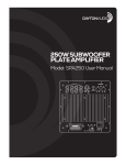
70 Watt Subwoofer Plate
Amplifier
Model: SA70
User Manual
daytonaudio.com
Thank you for purchasing the SA70 Subwoofer Plate Amplifier. It has been designed and built to provide years of
high quality sound reproduction, and is ideal for use in compact subwoofers for home stereo, home theatre, and multimedia audio systems. Engineering features of this amplifier include a choice of high or low level audio connections,
selectable crossover frequency, auto on/off circuit activated by input signal, and comprehensive internal production
against shorted speaker loads, thermal faults, and overload conditions.
FEATURES:
• Line-level and speaker-level inputs for connection to any audio system
• Full complement of protection circuits for high reliability
• Variable frequency 4th order low-pass crossover for a clean transition to main speakers
• Robust TDA7294 IC-based Class AB topology
• Auto-on feature conserves power when no signal is present
(2)
INPUT/OUTPUT CONNECTIONS
1.) Low-Level Inputs (Left/Right)
RCA style jacks that will accept standard line level inputs from a pre-amp level source. They will accept a stereo signal and
internally combine it into mono. (Note: Both left and right input jacks must be connected to the source in order to drive the
amplifier to full output).
2.) High-Level Inputs
Speaker level inputs using spring clip type jacks to permit connection with bare wire. Allows the user to connect the speaker
level output of a full range amplifier to the input of the subwoofer amp using standard speaker wire. A mono signal is derived
from the stereo input, which then feeds the subwoofer amplifier crossover input.
3.) High-Level Outputs
Speaker level passthrough outputs using spring clip type jacks to permit connection with bare wire. Used to connect from the
subwoofer amp to pass signal from the full range amp on to the main L/R speakers. Signal is only present on this output if
the high level input is also used. The signal to the L/R speakers is not filtered. The impedance “seen” by the full-range source
amplifier will be that of the connected speakers only.
4.) Power input
This unit features a hardwired AC power cable and externally-accessible fuse. It is supplied with a 1.6 A, 250V fuse and USA
type polarized 2-pin plug. This unit is not suitable for 230V applications.
CONTROLS/INDICATORS
5.) Gain Knob (“Gain”)
This control will match the amplifier’s input sensitivity to the output of the pre-amp source. If the source output has a variable
control, we recommend that the user spend a moment or two determining the best balance between the two controls. When
a balance is found between low noise, linear level control, and sufficient level to drive the amp to the required output, the gain
knob can be considered to be the “volume control” for the subwoofer system.
6.) Frequency Knob (“Freq”)
This control is used to establish the highest frequency that the subwoofer will reproduce and has a range between 60 to 180
Hz with a slope of 24 dB per octave. If you are using the system for music and your main speakers have good bass capability,
you could set the control to a fairly low value, often between 60 and 100 Hz. If the main speakers are smaller or do not have
much bass output, set the control higher. Experiment with the amount of “overlap” that you will experience when all speakers are playing in the same range. This can be helpful when integrating the subwoofer with the rest of the system and with
the room. Note: When using the amp with a LFE (Low Frequency Effects) output on a pre-amp or home theatre receiver the
internal low pass filter circuitry should be bypassed by turning the frequency control to maximum (180Hz). The home theater
receiver should be used to control the low pass crossover frequency.
7.) Power LED
When the power switch is moved to the “on” position, the LED will illuminate green, and the amp will be in “On” mode. When
set in the “Auto” position the unit will be in the stand by mode. In this position, if a low level signal of about 10 millivolts or
greater is applied to the input, the light will change green to indicate that the amplifier is fully operational and receiving typical
music program. If an input signal is not detected for 10 to 15 minutes, the amp will go back to “stand by” mode and the LED
will turn off. If the protection circuit detects a short circuit or thermal overload the unit will shut down and the LED will turn red.
8.) Power Switch
On, Off and Auto mode. When the “Auto” position is selected, the amp is in “stand by” mode until an input signal of about 10
millivolts or greater is detected. The amp will go back to standby mode 10-15 minutes after the input signal stops.
9.) Output Lead for Subwoofer Driver:
This rear mounted output lead connects the amplifier to the subwoofer driver. The output lead is roughly 12" long and is color
coded. The red wire uses an insulated .250" quick disconnect and the black wire uses an insulated .205" quick disconnect.
These connectors can be easily removed if your driver requires another size or type of connector. Be sure to observe proper
polarity when connecting the amplifier to your subwoofer driver (red = positive, black = negative).
(3)
NOTES ABOUT HUM:
While the SA70 has been designed to minimize the possibility of hum in the subwoofer system, it is still possible that a hum
will occur in rare circumstances. Its safety grounding can create a path for small amounts of 60 Hz energy to travel through
the line-level audio system. While not dangerous, this energy can cause difficulty with the subwoofer auto signal sensing
circuit, and at the very least will interfere with the quiet enjoyment of your system. The first course of action should be trying to
make sure that all of the audio components are connected to either the same electrical outlet, or at least into the same circuit
branch. Next, cable TV systems are notoriously the culprit, so be sure to try disconnecting all coaxial feeds that are connected
to the system. If this solves the problem, install a coaxial line isolator and reconnect the system. In the very worst case, a linelevel audio isolator/transformer connected to the line-in of the subwoofer amplifier will usually solve the problem.
SPECIFICATIONS:
Rated Power Output: Signal to Noise Ratio:
Input Impedance:
Low Pass Adjustment:
Dimensions:
Enclosure Cutout:
Power Requirements:
Stand-By Power Rating:
Weight:
45 watts RMS into 8 ohms @ 0.1% THD
70 watts RMS into 4 ohms @ 0.2% THD
90 dB A-weighted
10.4K ohms
60 Hz – 180 Hz
7-1/2" W x 8-11/16" H x 3-1/2” D
6-5/8" W x 7-3/4" H
120 VAC, 60 Hz, 110W
N/A
5.8 lbs.
Important Safety Instructions
Read these instructions – All the safety and operating instructions should be read before this product is operated.
Keep these instructions – The safety and operating instructions should be retained for future reference.
To reduce the risk of electric shock, do not remove cover. No user serviceable parts inside. The unit should be connected to an earth grounded AC electrical socket. Do not defeat the safety purpose of the polarized or grounding plug. If the provided plug does not fit into your outlet, consult an electrician for
replacement of the obsolete outlet. Refer servicing to qualified personnel. To reduce the risk of fire and shock do not expose unit to rain or moisture. Clean
only with dry cloth. Unplug the unit during lightning storms or when unused for long periods of time.
The unit should be operated in a well ventilated area. Minimum clearance is 2 inches from the ventilation openings. Do not install near any heat sources such
as radiators, heat registers, stoves, or other apparatus (including amplifiers) that produce heat. Protect the power cord from being walked on or pinched, particularly at the plugs, convenience receptacles, and at the point where they exit the unit. Only use attachments/accessories specified by the manufacturer.
Note: Unit is set at the factory for 115V operation. Unit may not be adjusted or modified for 230V operation.
Warranty Information
Dayton Audio® products are constructed by industry experts, and are thoroughly tested before shipment. Dayton Audio® products are warranted for
the period of one year. This warranty is limited to manufacturer defects, either in materials or workmanship. Dayton Audio® is not responsible for any
consequential on inconsequential damage to any other unit or component or the cost for installation or extraction of any component of the audio system.
In the rare case of a product failure, please contact your place of purchase or call our Customer Support Department at (937) 743-8248.
Warranty Limitations
There are no other warranties, either express or implied, which extend the foregoing, and there are no warranties of merchantability or fitness for any
particular purpose. The warranty will not cover incidental or consequential damage due to defective or improper use of products. This includes but is
not limited to burnt voice coils, overheating, bent frames, holes in the cone, or broken lead wires.
This warranty gives you specific legal rights and you may also have other rights which vary from state to state.
Non-Warranty Service: If non-warranty service is required, the product may be sent to the Company for repair/replacement, transportation prepaid,
by calling (937) 743-8248 for details, complete instructions, and service fee charges.
(4)
© Dayton Audio®
Last Revised: 5/24/2013