1
ENGLISH
FRANÇAIS
ESPAÑOL/CASTELLANO
DILA
PROJECTOR
Set up
DLARS4810
Getting Started
INSTRUCTIONS
Operate
Adjust/Set
Maintenance
Pour utilisation par le client :
Entrerci-dessous le N°de série qui
est situé sous le boîtier. Garder
cetteinformation comme référence
pour le futur.
Instrucción para el cliente :
Introduzca a continuación el nº de
serie que aparece en la parte
inferior lateral de la caja. Conserve
esta información como referencia
para uso ulterior.
N° de modèle DLA-RS4810
Modelo Nº DLA-RS4810
N° de série
Nº de serie
PC023483199
Others
Model No. DLA-RS4810
Serial No.
Troubleshooting
For Customer use :
Enter below the serial No. which is
located on the side of the cabinet.
Retain this information for future
reference.
Safety Precautions
Getting Started
IMPORTANT INFORMATION
This product has a High Intensity
Dis-charge (HID) lamp that contains
mercury.
Disposal of these materials may be
regulated in your community due to
environmental considerations. For
disposal or recycling information,
please contact your local authorities or
for USA, the Electronic Industries
Alliance: http://www.eiae.org.
WARNING:
TO PREVENT FIRE OR SHOCK HAZARDS, DO
NOT EXPOSE THIS APPLIANCE TO RAIN OR
MOISTURE.
WARNING:
THIS APPARATUS MUST BE EARTHED.
CAUTION:
To reduce the risk of electric shock, do not remove
cover. Refer servicing to qualified service personnel.
This projector is equipped with a 3-blade grounding
type plug to satisfy FCC rule. If you are unable to
insert the plug into the outlet, contact your electrician.
MACHINE NOISE INFORMATION
(Germany only)
Changes Machine Noise Information Ordinance 3.
GSGV, January 18, 1991: The sound pressure level
at the operator position is equal or less than 20 dB
(A) according to ISO 7779.
For the customers in Taiwan only
晼㯡婌♟㒷
FCC INFORMATION (U.S.A. only)
CAUTION:
Changes or modification not approved by JVC could
void the user’s authority to operate the equipment.
NOTE:
This equipment has been tested and found to comply
with the limits for Class B digital devices, pursuant to
Part 15 of the FCC Rules. These limits are designed
to provide reasonable protec tion against harmful
interference in a residential installation. This
equipment generates, uses, and can radiate radio
frequency energy and, if not installed and used in
accordance with the instruc tions, may cause harmful
interference to radio communications. However,
there is no guarantee that interference will not occur
in a particular installation. If this equipment does
cause harmful interference to radio or television
reception, which can be determined by turning the
equipment off and on, the user is encourage to try to
correct the interference by one or more of the
following measures:
Reorient or relocate the receiving antenna.
Increase the separation between the equipment
and receiver.
Connect the equipment into an outlet on a circuit
different from that to which the receiver is
connected.
Consult the dealer or an experienced radio/TV
technician for help.
Declaration of Conformity
Model Number : DLA-RS4810U
Trade Name : JVC
Responsible party : JVC AMERICAS CORP.
Address : 1700 Valley Road Wayne, N. J. 07470
Telephone Number : 973-317-5000
This device complies with Part 15 of FCC Rules.
Operation is subject to the following two conditions:
(1) This device may not cause harmful interference,
and (2) this device must accept any interference
received, including interference that may cause
undesired operation.
About the installation place
Do not install the projector in a place that cannot
support its weight securely.
If the installation place is not sturdy enough, the
projector could fall or overturn, possibly causing
personal injury.
2
IMPORTANT SAFEGUARDS
- All the safety and operating instructions should be read
before the product is operated.
- The safety and operating instructions should be retained for
future reference.
- All warnings on the product and in the operating
instructions should be adhered to.
- All operating instructions should be followed.
- Place the projector near a wall outlet where the plug can be
easily unplugged.
- Unplug this product from the wall outlet before cleaning.
- Do not use liquid cleaners or aerosol cleaners. Use a damp
cloth for cleaning.
- Do not use attachments not recommended by the product
manufacturer as they may be hazardous.
- Do not use this product near water. Do not use immediately
after moving from a low temperature to high temperature,
as this causes condensation, which may result in fire,
electric shock, or other hazards.
- Do not place this product on an unstable cart, stand, or
table. The product may fall, causing serious injury to a child
or adult, and serious damage to the product. The product
should be mounted according to the manufacturer’s
instructions, and should use a mount recommended by the
manufacturer.
PORTABLE CART WARNING
(symbol provided by RETAC)
- When the product is used on a cart,
care should be taken to avoid quick
stops, excessive force, and uneven
surfaces which may cause the product
and cart to overturn, damaging
equipment or causing possible injury to
S3126A
the operator.
- Slots and openings in the cabinet are provided for
ventilation. These ensure reliable operation of the product
and protect it from overheating. These openings must not
be blocked or covered. (The openings should never be
blocked by placing the product on bed, sofa, rug, or similar
surface. It should not be placed in a built-in installation such
as a bookcase or rack unless proper ventilation is provided
and the manufacturer’s instructions have been adhered to.)
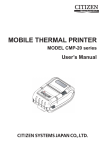
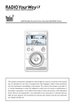
- To allow better heat dissipation, keep a clearance between
this unit and its surrounding as shown below. When this unit
is enclosed in a space of dimensions as shown below, use
an air-conditioner so that the internal and external
temperatures are the same. Overheating can cause
damage.
150 mm and above
300 mm
and above
300 mm
and above
Getting Started
Electrical energy can perform many useful functions.
This unit has been engineered and manufactured to
assure your personal safety. But IMPROPER USE
CAN RESULT IN POTENTIAL ELECTRICAL
SHOCK OR FIRE HAZARD. In order not to defeat
the safeguards incorporated into this product,
observe the following basic rules for its installation,
use and service. Please read these Important
Safeguards carefully before use.
- Power source indicated on the label. If you are not sure of
the type of power supply to your home, consult your
product dealer or local power company.
- This product is equipped with a three-wire plug. This plug
will fit only into a grounded power outlet. If you are unable
to insert the plug into the outlet, contact your electrician to
install the proper outlet. Do not defeat the safety purpose of
the grounded plug.
- Power-supply cords should be routed so that they are not
likely to be walked on or pinched by items placed upon or
against them. Pay particular attention to cords at doors,
plugs, receptacles, and the point where they exit from the
product.
- For added protection of this product during a lightning
storm, or when it is left unattended and unused for long
periods of time, unplug it from the wall outlet and
disconnect the cable system. This will prevent damage to
the product due to lightning and power line surges.
- Do not overload wall outlets, extension cords, or
convenience receptacles on other equipment as this can
result in a risk of fire or electric shock.
- Never push objects of any kind into this product through
openings as they may touch dangerous voltage points or
short out parts that could result in a fire or electric shock.
Never spill liquid of any kind on the product.
- Do not attempt to service this product yourself as opening
or removing covers may expose you to dangerous voltages
and other hazards. Refer all service to qualified service
personnel.
- Unplug this product from the wall outlet and refer service to
qualified service personnel under the following conditions:
a) When the power supply cord or plug is damaged.
b) If liquid has been spilled, or objects have fallen on the
product.
c) If the product has been exposed to rain or water.
d) If the product does not operate normally by following the
operating instructions. Adjust only those controls that
are covered by the Operation Manual, as an improper
adjustment of controls may result in damage and will
often require extensive work by a qualified technician to
restore the product to normal operation.
e) If the product has been dropped or damaged in any
way.
f) When the product exhibits a distinct change in
performance, this indicates a need for service.
- When replacement parts are required, be sure the service
technician has used replacement parts specified by the
manufacturer or with same characteristics as the original
part. Unauthorized substitutions may result in fire, electric
shock, or other hazards.
- Upon completion of any service or repairs to this product,
ask the service technician to perform safety checks to
determine that the product is in proper operating condition.
- The product should be placed more than one foot away
from heat sources such as radiators, heat registers, stoves,
and other products (including amplifiers) that produce heat.
- When connecting other products such as VCR’s, and DVD
players, you should turn off the power of this product for
protection against electric shock.
150 mm
and above
Front
200 mm
and above
3
Getting Started
- Do not place combustibles behind the cooling fan. For
example, cloth, paper, matches, aerosol cans or gas
lighters that present special hazards when over heated.
- Do not look into the projection lens while the illumination
lamp is turned on. Exposure of your eyes to the strong light
can result in impaired eyesight.
- Do not look into the inside of this unit through vents
(ventilation holes), etc. Do not look at the illumination lamp
directly by opening the cabinet while the illumination lamp is
turned on. The illumination lamp also contains ultraviolet
rays and the light is so powerful that your eyesight can be
impaired.
- Do not drop, hit, or damage the light-source lamp (lamp
unit) in any way. It may cause the light-source lamp to
break and lead to injuries. Do not use a damaged light
source lamp. If the light-source lamp is broken, ask your
dealer to repair it. Fragments from a broken light-source
lamp may cause injuries.
- The light-source lamp used in this projector is a high
pressure mercury lamp. Be careful when disposing of the
light-source lamp. If anything is unclear, please consult
your dealer.
- Do not ceiling-mount the projector to a place which tends to
vibrate; otherwise, the attaching fixture of the projector
could be broken by the vibration, possibly causing it to fall
or overturn, which could lead to personal injury.
- Use only the accessory cord designed for this product to
prevent shock.
- For health reasons, please take a break of about 5-15
minutes every 30-60 minutes and let your eyes rest. Please
refrain from watching any 3D-images when you feel tired,
unwell or if you feel any other discomfort. Moreover, in case
you see a double image, please adjust the equipment and
software for proper display. Please stop using the unit if the
double image is still visible after adjustment.
- Once every three years, please perform an internal test.
This unit is provided with replacement parts needed to
maintain its function (such as cooling fans). Estimated
replacement time of parts can vary greatly depending on
frequency of use and the respective environment. For
replacement, please consult your dealer, or the nearest
authorized JVC service center.
- When fixing the unit to the ceiling, Please note that we do
not take any responsibility, even during the warranty period,
if the product is damaged due to use of metal fixtures used
for fixation to the ceiling other than our own or if the
installation environment of said metal fixtures is not
appropriate. If the unit is suspended from the ceiling during
use, please be careful in regard to the ambient temperature
of the unit. If you use a central heating, the temperature
close to the ceiling will be higher than normally expected.
- Video images can burn into the electronic com ponent
parts. Please do not display screens with still images of
high brightness or high contrast, such as found in video
games and computer programs. Over a long period of time
it might stick to the picture element. There is no problem
with the playback of moving images, e.g. normal video
footage.
4
- Video images can burn into the electronic com ponent
parts. Please do not display screens with still images of
high brightness or high contrast, such as found in video
games and computer programs. Over a long period of time
it might stick to the picture element. There is no problem
with the playback of moving images, e.g. normal video
footage.
- Not using the unit for a long time can lead to malfunction.
Please power it on and let it run occasionally. Please avoid
using the unit in a room where cigarettes are smoked. It is
impos sible to clean optical component parts if they are
contaminated by nicotine or tar. This might lead to
performance degradation.
- Please watch from a distance three times the height of the
projected image size. Persons with photosensitivity, any
kind of heart disease, or weak health should not use 3D
glasses.
- Watching 3D-images might be cause of illness. If you feel
any change in your physical condition, please stop
watching immediately and consult a physician if necessary.
- When watching 3D images, it is recommended to take
regular breaks. As the length and frequency of the required
breaks differ for every person, please judge according to
your own condition.
- If your child watches while wearing 3D glasses, it should be
accompanied by its parents or an adult guardian. The adult
guardian should be careful to avoid situations where the
child’s eyes might become tired, as responses to tiredness
and discomfort, etc., are hard to detect, and it is possible
for the physical condition to deteriorate very quickly. As the
visual sense is not yet fully developed in children under the
age of 6, please consult a physician in regard to any
problem concerning 3D-images if necessary.
- Note that when using the 3D feature, the video output may
appear different from the original video image due to image
conversion on the device.
* DO NOT allow any unqualified person to
install the unit.
Be sure to ask your dealer to install the unit
(e.g.attaching it to the ceiling) since special
technical knowledge and skills are required for
installation. If installation is performed by an
unqualified person, it may cause personal injury or
electrical shock.
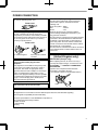
POWER CONNECTION
Power cord
The power supply voltage rating of this product is
AC110V – AC240V. Use only the power cord
designated by our dealer to ensure Safety and EMC.
Ensure that the power cable used for the projector is
the correct type for the AC outlet in your country.
Consult your product dealer.
Power cord
For United Kingdom
IMPORTANT (Europe only):
The wires in the mains lead on this product are
colored Vert et jaune in accordance with the
following cord:
Green-and-yellow : Earth
: Neutral
Blue
Brown
: Live
As these colors may not correspond with the
colored making identifying the terminals in your
plug, proceed as follows:
The wire which is colored green-and-yellow must be
connected to the terminal which is marked M with
the letter E or the safety earth or colored green or
green-and-yellow. The wire which is colored blue
must be connected to the terminal which is marked
with the letter N or colored black.
The wire which is colored brown must be connected
to the terminal which is marked with the letter L or
colored red.
POWER CONNECTION
(United Kingdom only)
For European continent
countries
WARNING:
Do not cut off the main plug from this
equipment.
If the plug fitted is not suitable for the power points
in your home or the cable is too short to reach a
power point, then obtain an appropriate safety
approved extension lead or adapter or consult your
dealer. If nonetheless the mains plug is cut off,
dispose of the plug immediately, to avoid a possible
shock hazard by inadvertent connection to the main
supply. If a new main plug has to be fitted, then
follow the instruction given below.
Getting Started
For USA and Canada only
Use only the following power cord.
IMPORTANT (Europe only):
When replacing the fuse, be sure to use only a
correctly rated approved type, re-fit the fuse cover.
IF IN DOUBT —— CONSULT A COMPETENT
ELECTRICIAN.
Open the fuse compartment with the blade
screwdriver, and replace the fuse.
(* An example is shown in the illustration below.)
WARNING:
THIS APPARATUS MUST BE EARTHED.
Fuse
Dear Customer,
This apparatus is in conformance with the valid European directives and standards regarding
electromagnetic compatibility and electrical safety.
European representative of JVC KENWOOD Corporation is:
JVC Technical Services Europe GmbH
Postfach 10 05 04
61145 Friedberg
Germany
5
ENGLISH
Getting Started
Information for Users on Disposal of Old Equipment and Batteries
[European Union only]
These symbols indicate that equipment with these symbols should not be disposed
of as general household waste. If you want to dispose of the product or battery,
please consider the collection systems or fa cilities for appr opriate recycling.
Battery
Products
Notice: The sign Pb below the symbol for batteries indicates that this battery
contains lead.
DEUTSCH
Benutzerinformationen zur Entsorgung alter Geräte und Batterien
[Nur Europäische Union]
Diese Symbole zeigen an, dass derartig gekennzeichnete Geräte nicht als normaler
Haushaltsabfall entsorgt werden dürfen. We nden Sie sich zur Entsorgung des
Produkts oder der Batterie an die hierfür vorgesehenen Sammelstellen oder
Einrichtungen, damit eine fachgerechte Wiederverwertung möglich ist.
Batterie
Produkte
Hinweis: Das Zeichen Pb unterhalb des Batteriesymbols gibt an, dass diese
Batterie Blei enthält.
FRANÇAIS
Informations relatives à l’élimination des appareils et des piles usagés, à l’intention
des utilisateurs
[Union européenne seulement]
Si ces symboles figurent sur les produits, cela signifie qu’ils ne doivent pas être
jetés comme déchets ménagers. Si vous voulez jeter ce produit ou cette pile,
veuillez considérer le système de collection de déc hets ou les centres de
recyclage appropriés.
Pile
Produits
Notification: La marque Pb en dessous du symbole des piles indique que cette
pile contient du plomb.
NEDERLANDS
Informatie voor gebruikers over het verwijderen van oude apparatuur en batterijen
[Alleen Europese Unie]
Deze symbolen geven aan dat appara tuur met dit symbool niet mag worden
weggegooid als algemeen huishoudelijk afval. Als u het product of de batterij wilt
weggooien, kun t u inzamelsystemen of faciliteiten voor een geschikte recycling
gebruiken.
Batterij
Producten
Opmerking: Het teken Pb onder het batterijsymboo l geeft aan dat deze batterij
lood bevat.
ESPAÑOL / CASTELLANO
Información para los usuarios sobre la eliminación de baterías/pilas usadas
[Sólo Unión Europea]
Estos símbolos indican que el equipo con estos símbolos no debe desecharse
con la basura doméstica. Si desea desechar el pro ducto o batería/pila, acuda
a los sistemas o centros de recogida para que los reciclen debidamente.
Baterías/pilas
Productos
6
Atención: La indicación Pb debajo del símbolo de batería/pila indica que ésta
contiene plomo.
ITALIANO
Getting Started
Informazioni per gli utenti sullo smaltimento delle apparecchiature e batterie obsolete
[Solo per l’Unione Europea]
Questi simboli indicano che le apparecchiature a cui sono relativi non devono
essere smaltite tra i rifiuti domestici generici. Se si desidera smaltire questo
prodotto o questa batteria, prendere in considerazione i sistem i o le strutture di
raccolta appropriati per il riciclaggio corretto.
Batteria
Prodotti
Nota: Il simbolo Pb sotto il simbolo delle batter ie indica che questa batteria contiene
piombo.
PORTUGUÊS
Informação para os utilizadores acerca da eliminação de equipamento usado e pilhas
[Apenas União Europeia]
Estes símbolos indicam que o equipamento com estes símbolos não deve ser
eliminado juntamente com o restante lixo doméstico. Se p retende eliminar
o produto ou a pilha, utilize os sistemas de recolha ou instalações para uma
reciclagem apropriada.
Pilha
Produtos
Aviso: O sinal Pb abaixo do símbolo para pilhas indica que esta pilha contém
chumbo.
ΕΛΛΗΝΙΚΑ
Πληροφορίες για την απόρριψη παλαιού εξοπλισμού και μπαταριών
[ Ευρωπαϊκή Ένωση μόνο ]
Αυτά τα σύμβολα υποδηλώνουν ότι ο εξοπλισμός που τα φέρει δεν θα πρέπει
να απορριφθεί ως κοινό οικιακό απόρριμμα . Εάν επιθυμείτε την απόρριψη
αυτού του προϊόντος ή αυτής της μπαταρίας , χρησιμοποιήστε το σύστημα
περισυλλογής ή εγκαταστάσεις για ανάλογη ανακύκλωση .
Μπαταρία
Προϊόντα
Σημείωση: Το σύμβολο Pb κάτω από το σύμβολο μπαταρίας υποδηλώνει ότι
η μπαταρία περιέχει μόλυβδο .
DANSK
Brugerinformation om bortskaffelse af gammelt udstyr og batterier
[Kun EU]
Disse symboler angiver, at udstyr med disse symboler ikke må bortskaffes som
almindeligt husholdningsaffald. Hvis du ønsker at smide dette produkt eller batteri
ud, bedes du overveje at bruge indsamlingssystem et eller steder, hvor der kan
ske korrekt gen brug.
Batteri
Produkter
Bemærk: Tegnet Pb under symbolet for batterierne angiver, at dette batteri
indeholder bly.
SUOMI
Tietoja vanhojen laitteiden ja akkujen hävittämisestä
[Vain Euroopan unioni]
Nämä symbolit ilmaisevat, että symboleilla merk ittyä laitetta ei tulisi hävittää
tavallisen kotitalousjätteen mukana. Jos haluat hävit tää tuotteen tai sen akun,
tee se hyödyntämällä akkujen keräyspisteitä tai muita kier rätyspaikkoja.
Akku
Tuotteet
Huomautus: Akkusymbolin alapuolella oleva Pb-merk intä tarkoit taa, että akku
sisältää lyijyä.
7
SVENSKA
Getting Started
Information för användare gällande bortskaffning av gammal utrustning och batterier
[Endast den Europeiska unionen]
Dessa symboler indikerar att utrustning med dessa symboler inte ska hanteras
som vanligt hushållsavfall. Om du vill bortsk affa produkten eller batteriet ska du
använda uppsamlingssystem eller inrättningar för lämplig återvinning.
Batteri
Produkter
Observera: Märkningen Pb under symbolen för batterier indikerar att detta batteri
innehåller bly.
NORSK
Opplysninger til brukere om kassering av gammelt utstyr og batterier
[Bare EU]
Disse symbolene viser at utstyr med dette symbolet, ikke skal kastes sammen
med vanlig husholdningsavfall. Hvis du vil kass ere dette produkte t eller batteriet,
skal du vurdere å bruke innsam lingssystemene eller andre muligheter for riktig
gjenbruk.
Batteri
Merk: Tegnet Pb under symbolet for batterie r, viser at batteriet inneholder bly.
Produkter
Сведения для пользователей по утилизации старого оборудования и батарей
[только для Европейского союза]
Данные символы указывают на то, что оборудование, на которое они
нанесены, не должны утилизироваться, как обычные бытовые отходы. При
необходимости утилизировать такое изделие или батарею обратитесь в
специальный пункт сбора для их надлежащей переработки.
Батарея
Изделия
Уведомление: Надпись Pb под символом батар ей указывает на то, что
данная батарея содержит свинец.
Informace pro uživatele k likvid aci starého zařízení a baterií
[Pouze Evropská unie]
Tyto symboly označují, že produkty s těmito symboly se nesmí likvidovat jako
běžný odpad. Pokud chcete produkt nebo baterii zlikvidovat, využijte sběrný
systém nebo jiné zařízení, které zaji stí řádnou recyklaci.
Baterie
Produkty
Bemærk: Značka Pb pod symbolem pro ba te rie znamená, že tato baterie
obsahuje olovo.
POLSKI
Informacje dla użytkowników dotyczące poz bywania się zużytego sprzętu i baterii
[Tylko kraje Unii Europejskiej]
Te symbole oznaczają, że sprzę tu nie należy wyr zucać razem z odpadami
gospodarczymi. Jeśli trzeba po zbyć się tego produktu lub ba terii, proszę
skorzystać z systemu odbioru lub urządzeń do zbió rki odpadów elektronicznych,
w celu odpowiedniego ponowne go ich przetworzenia.
Bateria
Produkty
8
Uwaga: Oznaczenie Pb, znajdujące się pod symbole m baterii wskazuje, że ta
bateria zawiera ołów.
MAGYAR
Getting Started
Felhasználói információ az elhasznált be rendezések és akkumulátorok elhelyezéséről
[Csak az Európai Unióban]
Ez a szimbólum azt jelzi, hogy a berendezés nem helyezhető az általános
háztartási hulladék közé. Ha meg szeretne szabadulni a terméktől vagy az
akkumulátortól, akkor legyen tekintettel az gyűjtő rendszerre vagy intézményekre
a megfelelő hasznosítás érdekében.
Akkumulátor Megjegyzés: Az alábbi Pb szimbólum - ha az akkum ulátoron megtalálható - azt
Termékek
jelzi, hogy az akkumulátor ólmot tartalmaz.
Cрпска
Informacije za korisnike o odlaganju stare opreme i baterija
[Samo u zemljama gde se primenjuje]
Ovi simboli ukazuju da proizvod i baterije sa ovim simbolom ne smeju biti odloženi
kao nesortiran kućni otpad. Ako želite da ih se rešite, molimo vas da ne
upotrebljavate običnu kantu za đubre. Postoje zasebni sistemi za prikupljanje
ovakvih proizvoda.
Baterija
Produkt
Naznaka: Hemijski simbol Pb ispod simbola za baterije ukazuje na to da li baterija
sadrži olovo.
9
Contents
Getting Started
Safety Precautions .................................................. 2
Accessories/Optional Accessories ........................ 11
Check the Accessories ...................................... 11
Optional Accessories ......................................... 11
Main Features ....................................................... 12
Controls and Features ........................................... 14
Main Unit Front ................................................ 14
Main Unit Bottom ............................................. 14
Main Unit Rear ................................................. 15
Main Unit Input Terminals ................................ 16
Remote Control ................................................. 17
Loading Batteries into the Remote Control ........ 18
Effective Range of Remote Control Unit ............ 18
Set up
Installing the Projector ........................................... 19
Precautions during Installation ........................... 19
Precautions during Mounting ............................. 20
Adjusting the Position ........................................ 21
Connecting the Projector ....................................... 22
Connecting to the HDMI Input Terminal (Digital
Input) ................................................................. 22
Connecting to the Component Video Input Terminal
(Analog Input) .................................................... 23
Connecting to the LAN Terminal ........................ 24
Connecting to the RS232C Terminal ................ 24
Connecting to the REMOTE Terminal ............... 24
Connecting to the TRIGGER Terminal ............... 25
Connecting the Power Cord (Supplied Accessory) ...... 25
Operate
Viewing Videos ...................................................... 26
Adjusting the Projector Screen .............................. 28
Adjusting the Lens According to the Projection
Position .............................................................. 28
Saving and Retrieving Adjustment Settings ....... 29
Adjusting Image Quality Automatically According to
the Viewing Environment ................................... 31
Setting Screen Correction .................................. 32
Adjusting the Screen Size (Aspect) ................... 33
Viewing 3D Movies ................................................ 34
Installing the 3D SYNCHRO EMITTER .............. 34
Viewing 3D Movies ............................................ 35
Converting 2D Movies to 3D Movies for Viewing ....... 35
Adjusting 3D Movies .......................................... 36
10
Adjust/Set
Selecting an Image Quality According to the Video
Type ...................................................................... 37
Setting the Picture Mode ................................... 37
Setting the Color Profile ..................................... 38
Adjusting Movies for Increased Expressiveness
(Multiple Pixel Control) .......................................... 39
Finetuning the Image Quality ............................... 40
Adjusting the Output Value of the Projected Image
(Gamma) ........................................................... 40
Adjusting to the Preferred Gamma Setting (Custom
Gamma) ............................................................ 41
Compensating Highlights and Shadows (Dark/
Bright Level) ...................................................... 42
Adjusting to the Preferred Color (Color
Management) .................................................... 43
Reducing the Afterimage of Fastmoving Images
(Clear Motion Drive (C.M.D.)) ............................ 44
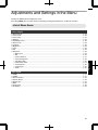
Adjustments and Settings in the Menu .................. 45
LIst of Menu Items ............................................. 45
Picture Adjust .................................................... 47
Input Signal ........................................................ 51
Installation ......................................................... 53
Display Setup .................................................... 59
Function ............................................................. 60
Information ......................................................... 62
Maintenance
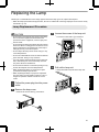
Replacing the Lamp .............................................. 63
Lamp Replacement Procedure .......................... 63
Resetting the Lamp Time ................................... 65
Maintaining the Cabinet and Remote Control ........ 65
Cleaning and Replacing the Filter ......................... 66
Troubleshooting
Troubleshooting .................................................... 67
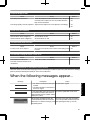
When the following messages appear... ................ 69
Others
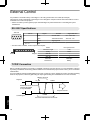
External Control .................................................... 70
RS232C Specifications ..................................... 70
TCP/IP Connection ............................................ 70
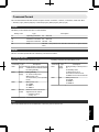
Command Format .............................................. 71
Remote Control Code ........................................ 72
Communications Example ................................. 73
Specifications ........................................................ 74
Index ..................................................................... 82
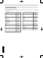
Accessories/Optional Accessories
Getting Started
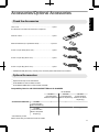
Check the Accessories
Lens Cover ............................................................................. 1 piece
*It is attached to the main unit at the time of shipment.
Remote control ....................................................................... 1 piece
AAAsize batteries (for operational check) ............................ 2 pieces
Power cord (for USA) (about. 2 m) ......................................... 1 piece
Power cord (for UK) (about. 2 m) ............................................ 1 piece
Power cord (for EU) (about. 2 m) ............................................ 1 piece
INSTRUCTIONS (this book), warranty card, and other printed material are also included.
Optional Accessories
Replacement lamp model: PKL2312U
3D GLASSES models: PKAG2, PKAG3
3D SYNCHRO EMITTER: models PKEM1, PKEM2
Compatibility Chart for 3D SYNCHRO EMITTER and 3D GLASSES
3D GLASSES
PKAG1 *
PKAG2
PKAG3
(Communication
(Communication
(Communication
Method: IR (Infrared)) Method: IR (Infrared)) Method: RF (Radio
frequency))
3D SYNCHRO EMITTER
PKEM1
(Communication
Method: IR (Infrared))
X
X
—
PKEM2
(Communication
Method: RF (Radio
frequency))
—
—
X
* Discontinued product
Please check with your authorized dealer for details.
11
Main Features
Getting Started
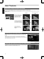
Highdefinition 4K display that surpasses full HD quality
The optical engine equipped with a new eshift2 device has achieved a resolution of 4K.
With JVC’s newlydeveloped imageprocessing algorithm, you can now enjoy the enhanced expressiveness of the 4K
quality. (p. 39)
Original
4K
3840×2160
3840×2160
Full HD
1920×1080
1920×1080
JVC’s Image Technology
Delivers a clearer expression with the jaggedness
and blurriness of the
oblique lines reduced
Contrast is enhanced even
for the details for them to
be reproduced realistically
Noise is reduced to
produce vivid and crisp
images
The photos are for illustrative purposes only.
3D video expressions with a highly realistic feel
With the 3D feature, you can enjoy 3D movies with a more realistic effect.
(p. 34)
With the 2D3D conversion feature, you can now enjoy 3D movies by
converting 2D videos of TV programs or those that are recorded using a home
video camera into 3D ones. (p. 35)
The photos are for illustrative
purposes only.
Optimal image quality adjustment according to the viewing environment
Halation that occurs in environments such as a living room with white walls is
taken into consideration for optimal viewing. (p. 31)
12
Flexible installation
The lens memory feature, which enables focus, zoom, or shift settings to be saved or retrieved, enables you to switch
to different video size formats easily.
Customizable image quality adjustment feature
You can make adjustments according to the type of video
images or your preferences to enjoy the videos in optimal
quality. (p. 37)
Real Color Imaging Technology (a color reproduction
technology developed by JVC) to enable reproduction in
an image quality that is closer to the original image.
(p. 38)
The photos are for illustrative purposes only.
Clear video expression with little afterimage (C.M.D.)
By employing the highdefinition image interpolation
technology developed by JVC, you can enjoy videos with
fast movements, such as sports, in a sharp quality.
(p. 44)
Sharp depiction of details with minimal blur
* C.M.D. is the abbreviation for Clear Motion Drive.
The photos are for illustrative purposes only.
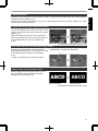
Highprecision pixel adjustment feature
With the highlyprecise “Pixel Adjust” feature, you can
enjoy a clear video quality with little color fringing
throughout the entire image. (p. 54)
ABCD
Before adjustment
ABCD
After adjustment
The photos are for illustrative purposes only.
13
Getting Started
In addition to the 2x motorized zoom & focus lens, the wide coverage of the lens shift functions also makes installation
of the projector more flexible. (p. 28)
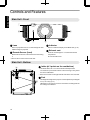
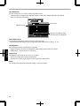
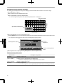
Controls and Features
Getting Started
Main Unit Front
C
D
D
B
A
A Lens
C Indicator
This is a projection lens. Do not look through the lens
while an image is projected.
B Remote Sensor (front)
Please aim the remote control at this area when using
it.
Refer to “Indicator Display on the Main Unit” (p. 79).
D Exhaust vent
Warm air is discharged to cool down the internal
temperature.
Do not block the vents.
* There is also a remote sensor at the rear.
Main Unit Bottom
E Inlets (at 3 points on the rear/bottom)
E
The inlets take in air to cool down the internal temperature.
Do not block or prevent the outflow of hot air. Doing so may cause
the unit to malfunction.
* There are two inlets on the right and left sides at the rear of the unit.
F Feet
F
14
The height and angle of the projector can be adjusted by turning the
foot. (0 to 5 mm) (p. 21)
When the foot is removed, it can be used as the mounting holes for
the ceiling mount bracket.
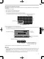
Getting Started
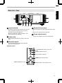
Main Unit Rear
E
E
H
G
K
J I
G Input terminals
In addition to the video input terminal, there are also
other connection terminals for devices such as
controllers and optional equipment.
Please see “Main Unit Input Terminals”p. 16 for
more details about the terminals.
H Lamp cover
J Remote Sensor (rear)
Please aim the remote control at this area when using
it.
* There is also a remote sensor at the front.
K Power input terminal
Connect the supplied power cord to this terminal.
When replacing the light source lamp, remove this
cover.
I Operation panel
For more details, please refer to the “Operation
panel” in the diagram below.
Operation panel
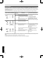
A [STANDBY/ON]: Turns “on”/“off” the
power
[INPUT]: Switches the input
[OK]: Confirms a selection
[JKH I] keys: Selects an item
[MENU]: Displays the menu
[BACK]: Returns to the previous menu
15
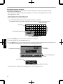
Getting Started
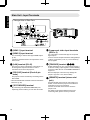
Main Unit Input Terminals
Enlarged View of Rear Face
A
B
C
D
F
G
E
A [HDMI 1] input terminal
B [HDMI 2] input terminal
For connecting to devices that support HDMI output.
(p. 22)
It is fitted to the M3 lock hole. The depth of the screw
hole is 3 mm.
C [LAN] terminal (RJ45)
The projector can be controlled by connecting it to a
PC through the computer network for control
commands to be sent to the projector.
D [RS232C] terminal (Dsub 9pin
male)
The projector can be controlled by connecting a PC to
this terminal.
* The LAN and RS232C terminals cannot be used at the
same time. (p. 60)
E [3D SYNCHRO] terminal
By connecting a 3D SYNCHRO EMITTER (sold
separately) to this terminal, you can view 3D movies.
16
H
F Component video input terminals
(RCA x 3)
For connecting to devices that support component
signal output.
It can be used as an input terminal for analog RGB (G
on Sync), component (Y, Cb, Cr), or DTV format (Y,
Pb, Pr) signals.
G [TRIGGER] terminal ()
Output terminal for DC 12V, 100 mA power supply. It
is used for sending output signals to control elevating
screens for which the use of a SCREEN TRIGGER is
supported.
Note that improper connection may damage the
projector. (Tip=DC +12 V, Sleeve=GND)
H [REMOTE] terminal (stereo mini
jack)
Use this terminal when a remote control unit is not
usable, such as when the projector is installed in a
dedicated box or for rear projection.
Connect an external remote sensor unit to the
projector unit.
For details on the external infrared sensor and
connecting cable, please contact your dealer.
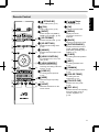
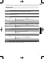
A B[STAND BY]
Turns off the power. (p. 27)
B C[ON]
A
B
C
D
E
Turns on the power. (p. 26)
C [INPUT]
Select an input from [HDMI 1],
[HDMI 2], and [COMP.]. (p. 26)
F D [3D FORMAT]
Switches the 3D format. (p. 35)
E [3D SETTING]
G
H
I
J
K
Displays the 3D setting menu.
(p. 35)
F [ANAMO.]
Switches the anamorphic mode.
(p. 55)
G [LENS CONTROL]
L
N
For adjusting focus, zoom, and
shift. (p. 28)
M H [LENS MEMORY]
O
Q
S
T
R
V
U
L [JKHI] keys
For selecting an item.
M [OK]
Confirms a selected item.
N [MENU]
Displays the menu,
or hides the menu if it is
displayed.
O [BACK]
Returns to the previous menu.
P [PICTURE MODE]
Switches the Picture mode to
[FILM], [CINEMA], [ANIME],
[NATURAL], [STAGE], [3D], or
[USER]. (p. 37)
Q [C.M.D.]
For setting frame interpolation.
(p. 44)
R [MPC]
For setting the MPC level.
(p. 39)
Switches between saving,
retrieving, and editing of the lens
memory. (p. 29)
S [GAMMA]
For setting the lens aperture.
(p. 50)
T [COLOR TEMP]
Hides the image temporarily.
(p. 26)
U [COLOR P.FILE]
Illuminates the buttons on the
remote control.
V [PIC. ADJ.]
I [LENS AP.]
P
J [HIDE]
K [LIGHT]
Getting Started
Remote Control
For setting the gamma level.
(p. 40)
For setting the color
temperature. (p. 47)
Switches the color profile.
(p. 38)
Switches the items for adjusting
the image quality, such as
contrast, brightness, etc.
(p. 48)
17
Getting Started
Loading Batteries into the Remote Control
If the remote control has to be brought closer to the projector to operate, it means that the batteries are wearing out.
Replace the batteries with new ones (AAA).
Insert the batteries according to the ts marks. Be sure to insert the s end first.
If an error occurs while using the remote control, remove the batteries and wait for five minutes. Load the batteries
again and operate the remote control.
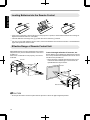
Effective Range of Remote Control Unit
When aiming the remote control toward the sensor on this
unit (front or rear), ensure that the distance to the sensor
is within 7 m.
If the remote control fails to work properly, move closer
to this unit.
This unit
Control through reflection off a screen, etc.
Ensure that the total of distance A (between this unit and
the screen) and distance B (between the remote control
and the screen) is within 7 m.
* As the efficiency of signals reflected from the remote
control unit varies with the type of screen used, the
operable distance may decrease.
30°
Screen
30°
20°
30°
20°
30°
Remote Control
20°
20°
This unit
A
B
Remote Control
CAUTION
18
Do not put the remote control in a place with an exposure to direct sun light or high temperature.
Installing the Projector
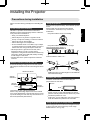
Precautions during Installation
Do not install at the following
Projection with the unit inclined at an angle
Horizontal inclination: within ± 5 °
5°
5°
Vertical inclination: within ± 15 °
300 mm
and above
150 mm
and above
Front
300 mm
and above
15°
150 mm and above
15°
As the unit discharges a large amount of heat, install it
with adequate clearance from the surroundings as shown
below.
15°
Maintain clearance from the wall, etc.
Malfunction may occur if the angle is not set within the
abovementioned range.
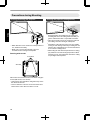
Installing the screen
Install the unit and the screen such that they are
perpendicular to each other.
Screen
200 mm
and above
Leave the front area of the unit unblocked.
If there is any obstructing object in front of the exhaust
vent, hot air will flow back to the unit and cause it to heat
up. Hot air flowing out of the unit may cause shadows on
the screen (heat haze phenomenon).
Front
Please choose a screen material with nonuniform
patterns. Uniform patterns such as checks may cause
interference patterns to occur.
In this case, you can change the size of the screen to
make the interference patterns less noticeable.
Using the projector at a high altitude
When using this unit at a location that is higher than 900
m above sea level (low air pressure), set the “High
Altitude Mode” to “On”. (p. 60)
19
Set up
This unit is a precision device. Please refrain from
installing or using it at the following locations. Otherwise,
it may cause fire or malfunction.
Dusty, wet and humid places
Places subject to oily smoke or cigarette smoke
On top of a carpet or bedding, or other soft surfaces
Places exposed to direct sunlight
Places with a high or low temperature
Do not install this unit in a room that is oily or subject
to cigarette smoke. Even a small quantity of smoke or
oiliness can have a longterm impact on this unit.
* This unit produces a great amount of heat, and is
designed to take in cool air to cool its optical
components. Using the unit at the above locations may
cause dirt to attach to the light path, thereby resulting
in dark images or dull colors.
* Dirt that sticks to the optical components cannot be
removed.
Using the projector
This unit uses a projection lamp, which will heat up when
in use.
Please refrain from projecting in the following
circumstances. Otherwise, it may cause fire or
malfunction.
Projection with the unit stood vertically
15°
Please read the following carefully before installing this
unit.
Precautions during Mounting
Securing (mounting) the projector
Securing the projector (ceiling mount)
Set up
When this unit is to be mounted to a fixed position for
use, install it horizontally.
Make sure to secure the main unit to prevent
accidents such as during an earthquake.
Securing with screws
4 Locations
Air Inlets
Remove the four feet at the bottom, and fasten using the
screws (M5 screws, 13 to 23 mm).
* Using screws other than those designated may cause
the unit to break down.
* Leave a clearance of at least 10 mm from the bottom
surface of the unit to allow it to take in cool air.
20
Special expertise and techniques are required for
mounting this unit to the ceiling. Make sure that you
get the authorized dealer or a specialist to install it.
Take the necessary actions to prevent the main unit
from falling off such as during an earthquake.
Regardless of the warranty period, JVC is not liable
for any product damage caused by mounting the unit
with nonJVC ceiling fittings or to an environment that
is not suited for ceiling mount.
When using the unit with it suspended from a ceiling,
pay attention to the surrounding temperature. When
a heater is in use, the temperature around the ceiling
may be higher than expected.
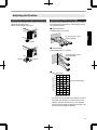
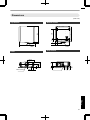
Adjusting the Position
Adjusting the elevation angle of the projector
The height and inclination of the unit (0 to 5 mm) can be
adjusted by turning the feet.
Lift the unit and adjust the four feet.
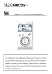
Adjusting the position of the image
By using the lens shift feature of this unit, you can shift
the image upward/downward or to the left/right. Set it to
your preferred position.
■ Horizontal Position
Vertical Position: 0% (Center)
Set up
Up to about 34% of the
projected image
Feet
■ Vertical Position
Horizontal Position: 0 % (Center)
Up to about 80% of the
projected image
Contract
■ Lens shift Range
90
80
Vertical lens shift (%)
Extend
70
Lens movement range
60
50
40
30
20
10
0
10
20
30 40
Horizontal lens shift (%)
The maximum vertical shift varies with the amount of
horizontal shift. Similarly, the maximum horizontal
shift also changes with the amount of vertical shift.
The values on the graph are intended as a guide. Use
them for reference during installation.
21
Connecting the Projector
Do not turn on the power until connection is complete.
The connection procedures differ according to the device used. For details, please refer to the instruction manual
of the device to be connected.
This projector is used for projecting images. To output the audio of connected devices, please connect a separate
audio output device, such as an amplifier or speaker.
The images may not be displayed depending on the devices and cables to be connected.
Use only HDMI cables (sold separately) that are HDMIcertified.
Some cables cannot be connected to this unit due to the size of their connector cover.
Set up
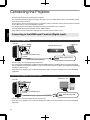
Connecting to the HDMI Input Terminal (Digital Input)
Connecting via HDMI cable
This Unit
Laptop, etc.
BD/DVD Recorder, etc.
To [HDMI 1] or [HDMI 2] input
terminal
HDMI Output Terminal
HDMI Cable (Sold Separately)
If noise occurs, move the laptop away from this unit.
For a transmission bandwidth in compliance with the HDMI standard, a 340 MHz cable is recommended. When
using a cable with a bandwidth of 75 MHz, you are recommended to set the resolution of the equipment transmitting
the video to 1080i or lower.
If the video is not displayed, try to reduce the length of the cable or lower the resolution of the video transmitting
equipment.
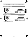
Connecting via HDMIDVI conversion cable
Desktop PC, etc.
This Unit
To [HDMI 1] or [HDMI 2] input
terminal
DVI Output Terminal
HDMI-DVI Conversion Cable (Sold Separately)
22
If noise occurs, move the desktop PC away from this unit.
If the video is not displayed, try to reduce the length of the cable or lower the resolution of the video transmitting
equipment.
Connecting to the Component Video Input Terminal (Analog Input)
Connecting via component video cable
This Unit
BD/DVD Recorder, etc.
Component Video Cable (Sold Separately)
Set up
To component video
input terminals
Component Video Output Terminals
C R / P R (Red)
C B / P B (Blue)
(Green)
Y
Set “COMP.” to “Y Pb/Cb Pr/Cr” in the setting menu. (p. 51)
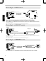
Connecting via RGB video cable
This Unit
Device Equipped with RGB
Output, etc.
To RGB Video Input
Terminals
RGB Video Cable (Sold Separately)
RGB Video Output Terminals
R (Red)
B (Blue)
G (Green) (Includes Sync Signal)
Set “COMP.” to “RGB” in the setting menu. (p. 51)
For more information on compatible input signals, please refer to “Specifications”p. 74.
23
Connecting to the LAN Terminal
Hub
This Unit
To [LAN] Terminal
Network
Connection Cable
(Sold Separately)
Set up
Server
Desktop PC, etc.
The network is used to control this unit. It is not used for sending or receiving video signals.
Please contact your network administrator for information concerning the network connection.
Set “ECO Mode” to “Off” if RS232C/LAN communication is performed or the HDMI link function is used in the
Standby mode. (p. 60)
For more information on control, please refer to “External Control” (p. 70).
Connecting to the RS232C Terminal
This Unit
Laptop, etc.
To [RS-232C] Terminal
RS-232C Terminal
RS-232C Connection Cable (Sold Separately)
Set “ECO Mode” to “Off” if RS232C/LAN communication is performed or the HDMI link function is used in the
Standby mode. (p. 60)
For more information on control, please refer to “External Control” (p. 70).
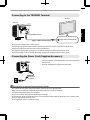
Connecting to the REMOTE Terminal
This Unit
To [REMOTE] Terminal
Connection Cable
(Sold Separately)
24
External Infrared Sensor
(Sold Separately)
For more information on the external infrared sensor and connecting cable, please contact your dealer.
Connecting to the TRIGGER Terminal
Screen
This Unit
Set up
To [TRIGGER] Terminal
Trigger Input Terminal (Ø3.5)
Trigger Cable (Sold Separately)
Do not use it to supply power to other devices.
Connecting to the audio terminal of another device may cause the device to malfunction or break down.
Using beyond the rated value will cause the unit to malfunction.
The trigger terminal outputs a voltage of 12 V. Exercise adequate caution to prevent short circuit.
The factory setting is “Off”. To change the setting, configure the “Trigger” item in the menu (p. 60).
Connecting the Power Cord (Supplied Accessory)
A Connect the power cord supplied to the power input terminal on
the main unit
B Insert the supplied power plug into the wall outlet.
A
Power Cord
(Supplied)
B
Precautions to prevent fire and electric shock
The voltage capacity of this unit is large. Please connect it directly to the wall outlet.
When you are not using the equipment, please unplug the power cord from the outlet.
Connect it using only the power cord supplied.
Do not use a voltage other than the indicated power voltage.
Do not damage, break or modify the power cord. Do not place a heavy object on the power cord, or heat or pull it.
Doing so may damage the power cord.
Do not unplug the power cord with wet hands.
25
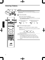
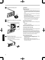
Viewing Videos
STANDBY/ON
LAMP
MEMO
WARNING
When you are using, be sure to remove the lens cover.
Connect the power cord, and ensure that the “STANDBY/ON” indicator
lights up in red.
Turn on the power
Remote control: press the C[ON] button
Projector unit: press the A[STANDBY/ON] button
The “STANDBY/ON” indicator light switches from red to green (light
goes off after the unit starts up).
3
1
“STANDBY/ON” lights up (red)
In standby state
Operate
2
TANDBY
ND
STANDBY/ON
LAMP
“STANDBY/ON” lights up (green)
During lamp startup
WARNING
TANDBY
ND
STANDBY/ON
LAMP
WARNING
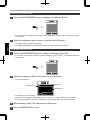
Choose the image to project
Remote control: press the [INPUT] button ([HDMI 1], [HDMI 2],
[COMP.])
Projector unit: press the [INPUT] button (pressing the button each time
switches the mode)
HDMI 1
HDMI 2
COMP.
Play back the selected device to project the image.
To hide the image temporarily
Press the [HIDE] button on the projector unit or remote control
The “STANDBY/ON” indicator light starts to blink in green.
Press the [HIDE] button again to resume display of the image.
26
The power cannot be turned off when the image is temporarily
hidden.
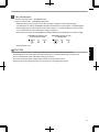
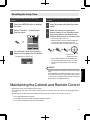
Turn off the power
Remote control: press the B[STAND BY] button
Projector unit: press the A[STANDBY/ON] button
While the “Are you sure you want to turn off?” message is displayed, press the button again.
The lamp turns off, and the “STANDBY/ON” indicator switches from a green light to a red blinking light.
After the light goes off, the fan will run for about 60 seconds to cool down the lamp (Cooldown mode)
Do not disconnect the power cable while cooling is in progress.
After about 60 seconds, the “STANDBY/ON” indicator switches from a blinking red to a solid red light.
“STANDBY/ON” blinking (red)
In the Cool-down mode
STANDBY/ON
LAMP
WARNING
“STANDBY/ON” lights up (red)
In standby state
STANDBY/ON
TANDBY
ND
LAMP
WARNING
Attach the lens cover.
Operate
CAUTION
The power cannot be turned off within approximately 90 seconds after it has been turned on.
After the light goes off, the fan will run for about 60 seconds to cool down the lamp (Cooldown mode)
Do not disconnect the power cable while cooling is in progress.
The power cannot be turned on again while cooling is in progress (60 seconds).
Pull out the power plug when the unit is not to be used for a prolonged period of time.
27
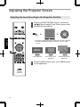
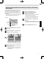
Adjusting the Projector Screen
Adjusting the Lens According to the Projection Position
Press the [LENS CONTROL] button, and use the
[JKHI] keys to adjust Focus, Zoom (screen size),
and Shift (screen position)
Lens Control
Focus
1
Operate
Select
Operate
BACK
Pressing the [LENS CONTROL] or [OK] button each time switches
the mode in the following sequence: “Focus”“Zoom”“Shift”
“Focus”...
ABCD
2
Focus Adjustment
28
Back
Zoom (Screen Size)
Adjustment
Shift (Screen Position)
Adjustment
Press the [BACK] button once, or the [MENU] twice,
to end adjustment.
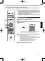
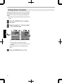
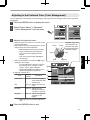
Saving and Retrieving Adjustment Settings
The focus, zoom, and shift settings can be saved or retrieved, so you can
switch easily to a different aspect ratio (screen size) according to the image.
Pressing the [LENS MEMORY] button each time switches the mode in the
following sequence: “Lens Memory Save”“Lens Memory Select”“Lens
Memory Name Edit”“Lens Memory Save”...
In a state where no adjustment settings are saved (factory default), only
“Lens Memory Save” is displayed.
Saving an adjustment data
Adjust focus, zoom, or shift (p. 28)
Press the [LENS MEMORY] button to display “Lens
Memory Save”
2
Operate
3
Installation
>> Lens Memory Save
-----------------
4
------------------------Operate
Exit
MENU
Back
BACK
You can also save an adjustment data by selecting “Installation”
“Lens Control”“Lens Memory Save” from the menu.
Select the item to save, and press the [OK] button
The adjustment data is saved.
Items with no adjustment data saved are displayed as [].
Select
If you have selected an item for which an adjustment data has already
been saved, the old data will be overwritten.
You can change the name when saving an item. (p. 30)
The maximum number of items can be saved is 5.
Press the [MENU] button to exit
29
Retrieving an adjustment data
Press the [LENS MEMORY] button to display “Lens Memory Select”
Installation
>> Lens Memory Select
MEMORY1
MEMORY2
--------------------------------Operate
Exit
Back
BACK
Select
MENU
You can also retrieve an adjustment data by selecting “Installation”“Lens Control”“Lens Memory Select”
from the menu.
Select the adjustment data to retrieve, and press the [OK] button
Operate
The retrieved data is adjusted automatically.
If no adjustment data has been saved, the item will be grayed out and cannot be selected.
Renaming an adjustment data
Press the [LENS MEMORY] button to display “Lens Memory Name Edit”
You can also edit an adjustment data by selecting “Installation”“Lens Control”“Lens Memory Name Edit”
from the menu.
Installation
>> Lens Memory Name Edit
MEMORY1
MEMORY2
--------------------------------Operate
Exit
Back
BACK
Select
MENU
Select the adjustment data to edit, and press the [OK] button
An edit screen appears.
Installation
>> User Name Edit
Input Cursor
User 1
Selection Cursor
A
B
C
D
E
F
G
H
I
J
K
L
M
N
O
P
Q
R
S
T
U
V
W
X
Y
Z
a
b
c
d
e
f
m
g
h
i
j
k
l
n
o
p
q
r
s
t
y
v
w
x
y
1
2
3
4
5
6
7
8
9
0
,
.
^
!
"
#
$
%
&
*
+
-
/
=
?
@
;
|
~
)
<
>
[
]
{
}
\
:
SPACE
All Clear
Operate
Exit
MENU
(
Clear
Select
z
Character List
OK
Back
BACK
You can input up to 10 characters.
Characters that are usable include alphabets (upper or lower case), numeric characters, and symbols.
Pressing the [Back] button cancels the content that is currently being edited, and exits the edit mode.
After renaming, select “OK” and press the [OK] button
Press the [MENU] button to exit
30
Adjusting Image Quality Automatically According to the Viewing
Environment
By configuring “Environment Setting” according to the
viewing environment, image quality adjustment and
correction according to environmental differences are
performed automatically to minimize any influence on the
image quality.
“Environment Setting” is applied separately from the
individual image adjustment settings (p. 47).
Select “Viewing Distance” to
configure the viewing distance
(distance to the screen)
- Front View Screen
Screen Size
Projector
Press the [MENU] button to display
the menu
Select “Installation”“Environment
Setting”“On” from the menu
Installation
>> Environment Setting
Pixel Adjust
Environment Setting
Front
Screen Size
Keystone
Pincushion
0
Anamorphic
Press the [MENU] button to exit
Installation
Lens Control
Installation Style
If the wall is black in color, select “Dark”. For
walls with a color other than black, select “Light”
.
On
100inch
Viewing Distance
3.0H
Wall Color
Light
On
Off
Off
Screen Adjust
Environment Setting
Operate
Exit
MENU
Select
Back
BACK
Operate
Exit
MENU
Select
Back
BACK
When “Environment Setting” is set to “Off”,
“Screen Size”, “Viewing Distance”, and “Wall
Color” are grayed out and cannot be selected.
Select “Screen Size” to configure the
screen size to use
Select the closest screen size setting from the
range between “60inch” and “200inch” (in 10
inch increments).
31
Operate
Viewer
For more details on the height, please refer to
“Screen Size and Projection Distance”p. 75.
Select “Wall Color” to configure the
wall color
Viewing
Distance
Select the closest viewing distance setting from
the range between “1 m” and “10 m”.
Setting Screen Correction
By selecting the optimal correction mode according to the
characteristics of the screen in use, corrections can be
performed to reproduce natural images with balanced
colors.
This function is disactivated when “Color Profile” is set
to “Off”.
Press the [MENU] button to display
the menu
Select “Installation”“Screen Adjust”
“On” from the menu
Installation
Installation
Lens Control
Lens Control
Operate
Pixel Adjust
Pixel Adjust
Installation Style
Installation Style
Front
Pincushion
0
Anamorphic
Off
Screen Adjust
Screen Adjust
On
Environment Correction
Environment Correction
Off
Operate
Exit
MENU
Pincushion
0
Anamorphic
Front
Keystone
Keystone
Select
Back
BACK
MENU
A
B
C
Operate
Exit
Off
Select
Back
BACK
Select one from the three types (“A”, “B”, or “C”
).
For information on the screen and the
corresponding correction mode, please visit our
website.
http://www3.jvckenwood.com/english/projector/
screen/
32
Press the [MENU] button to exit
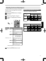
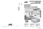
Adjusting the Screen Size (Aspect)
The screen size of the projected image can be adjusted
optimally according to the original screen size (aspect)
that has been input.
Press the [MENU] button to display
the menu
Select “Input Signal”“Aspect
(Video)” or “Aspect (PC)” from the
menu
Input Signal
Example of input image and screen size
HDMI input, component video input
Output Image
Input Image
Setting
4:3
16:9
Zoom
4:3
2.35:1
(Cinema
Scope)
HDMI
PC Input
COMP.
PC
Picture Position
Aspect (Video)
Mask
16:9
Auto
Output Image
3D Setting
Input Image
Operate
Exit
MENU
Operate
Off
Progressive
Select
Setting
Auto
Just
Full
Back
BACK
1280×1024
Input Signal
Aspect
(Video)
Setting
Description
4:3
Sets the screen size to 4:3. For
HD signals, the two sides are
reduced.
16:9
Sets the screen size to 16:9.
For SD signals, the two sides
are expanded.
Zoom
Enlarges the entire image.
1920×1200
*Not selectable in the
case of HD signals.
Aspect (PC) Auto
Positions the image at the
center with the entire image
enlarged.
Just
Displays the input image in the
actual size.
Full
Fills the entire screen with the
image with the size (aspect) of
the input image ignored.
During 3D signal input, the size is fixed at “16:9”
.
Press the [MENU] button to exit
33
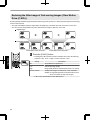
Viewing 3D Movies
By using the 3D GLASSES (PKAG1, PKAG2, or PKAG3) and 3D SYNCHRO EMITTER (PKEM1 or PKEM2), both
sold separately, you can enjoy 3D video images.
For 3D GLASSES and 3D SYNCHRO EMITTER that are compatible with this unit, please refer to “Optional
Accessories”p. 11.
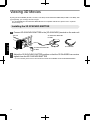
Installing the 3D SYNCHRO EMITTER
Connect 3D SYNCHRO EMITTER to the [3D SYNCHRO] terminal on the main unit
This Unit
3D SYNCHRO EMITTER
PK-EM1
Operate
3D GLASSES
3D SYNCHRO EMITTER
PK-EM2
Adjust the 3D SYNCHRO EMITTER position so that the 3D GLASSES can receive
signals from the 3D SYNCHRO EMITTER
34
For more details, please refer to the instruction manuals 3D GLASSES and 3D SYNCHRO EMITTER.
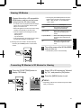
Viewing 3D Movies
Connect this unit to a 3Dcompatible
HDMI device, and turn on the power
to play back the 3D video image
For details on how to play back 3D video images,
please refer to the instruction manual of the
player or recorder in use.
When 3D signals are received, the video image
switches automatically to the 3D format.
This unit supports the following 3D formats.
Frame packing
Sidebyside
Topandbottom
In the default setting, “3D Format” is set to “Auto”
for automatic projection of 3D images.
Format
Description
Auto
The format is detected and
configured automatically.
Side by Side
Select this setting if the 3D input
signal is of the sidebyside
format.
Top and Bottom
Select this setting if the 3D input
signal is of the topandbottom
format.
2D
Select this setting if 2D images
are falsely recognized as 3D
ones.
Press the [3D FORMAT] button on the remote
control
Turn of the power of the 3D GLASSES
and put them on
The PKAG1 powers on automatically.
Converting 2D Movies to 3D Movies for Viewing
Press the [3D SETTING] button to
display “3D Setting”
Select “2D to 3D conversion” followed
by “On”, and press the [OK] button
Press the [MENU] button to exit
Input Signal
> 3D Setting
3D Format
2D to 3D conversion
Parallax
0
Crosstalk Cancel
0
Intensity
1
Sub Title Adjust
MENU
Off
Operate
Exit
Select
MEMO
Auto
Off
Depending on the movies, 3D effect may be less than
what you expected.
Back
BACK
35
Operate
If the image does not switch to 3D automatically
Pressing the [3D FORMAT] button each time
switches the mode in the following sequence:
“Auto”“Side by Side”“Top and Bottom”
“2D”“Auto”...
Adjusting 3D Movies
3D video images may appear differently to different
viewers. It may also be affected by your physical
condition at the time of viewing.
You are therefore recommended to adjust the video
images accordingly.
Press the [3D SETTING] button to
display “3D Setting”
Adjusting parallax (Parallax)
Adjust the displacement of the image for the left
and right eyes separately to obtain the best 3D
effect.
To do so, use the HI keys to move the cursor.
Setting range: 15 to +15
Operate
Adjusting crosstalk (Crosstalk Cancel)
Double images (overlapping of the left image with
the one on the right or vice versa) can be reduced
to deliver a clear quality.
To do so, use the HI keys to move the cursor.
Setting range: 8 to +8
* Adjustment cannot be made when “2D to 3D
conversion” is set to “On”.
Adjust the depth perception (Intensity)
The depth of the image can be adjusted to deliver
the best 3D effect during 2D3D image conversion.
To do so, use the HI keys to move the cursor.
Setting range: 1 to 5
* Adjustment can only be made when “2D to 3D
conversion” is set to “On”.
MEMO
Depending on the movies, 3D effect may be less than
what you expected.
Adjusting the subtitle display (Sub Title
Adjust)
If distortion occurs in the subtitle during 2D3D
image conversion, set to “On”.
* Adjustment can only be made when “2D to 3D
conversion” is set to “On”.
36
Press the [MENU] button to exit
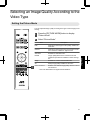
Selecting an Image Quality According to the
Video Type
Setting the Picture Mode
You can adjust the image quality according to the type of video image you are
viewing.
Press the [PICTURE MODE] button to display
“Picture Mode”
Select “Picture Mode”
Item
Reproduces the image in a film quality. Suitable for
all movies.
Cinema
Reproduces the image in vivid colors based on the
DCI* standard. Suitable for digital movies.
Animation
Suitable for animated works.
Natural
Image quality that focuses on natural color and
gradation reproduction. Suitable for drama footage,
etc.
Stage
Suitable for concerts or theatrical works.
3D
Sharp image quality suitable for 3D works.
User 1 to User 5
Enables userdefined image quality data to be saved
and retrieved.
* DCI is the abbreviation for Digital Cinema Initiatives.
37
Adjust/Set
1
Description
Film
Setting the Color Profile
By setting the “Color Profile” (color space information) according to the “Picture Mode”, you
can finetune the image quality according to the movie you are viewing.
After configuring “Picture Mode” (p. 37), press the [COLOR
P.FILE] button
Pressing the [COLOR P.FILE] button each time switches the “Color Profile” data for
the “Picture Mode” in sequence.
List of “Color Profile” for “Picture Mode”
Picture Mode
Film
Cinema
Animation
Adjust/Set
Natural
Stage
3D
User 1 to User 5
Color Profile
Description
Film
Color space that is suitable for all movies.
Standard
Color space of the HDTV* standard.
Cinema
Color space that is suitable for movies with vivid colors.
Standard
Color space of the HDTV* standard.
Anime
Color space that is suitable for animated works.
Standard
Color space of the HDTV* standard.
Natural
Color space that is suitable for drama footage, etc.
Standard
Color space of the HDTV* standard.
Stage
Color space that is suitable for concerts, theatrical performances, etc.
Standard
Color space of the HDTV* standard.
3D
Color space that is suitable for 3D movies.
Standard
Color space of the HDTV* standard.
Stage
When “Picture Mode” is set to any of the settings from “User 1” to “User 5”, you can
select one of the color profiles shown on the left.
Standard
Cinema
See above for the description of the respective color profiles.
Anime
Natural
Stage
3D
Off
Disables color space adjustment.
* HDTV is the abbreviation for High Definition Television.
38
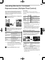
Adjusting Movies for Increased
Expressiveness (Multiple Pixel Control)
The new imageprocessing algorithm developed by JVC
helps to create a natural impression that is sharper at
areas in focus, and softer at areas that are not in focus,
enabling you to enjoy highly expressive 4K images with
a greater sense of depth.
Press the [MPC] button to display the
adjustment menu
Picture Adjust
>> MPC Level
FILM
4K Profile
Enhance
Finetuning
After selecting a content type, adjust “Enhance”,
“Dynamic Contrast”, and “Smoothing” according to your
preference.
Item
Setting
Range
Enhance
0 to 100
Enhances the sharpness of
the image.
Dynamic
Contrast
0 to 100
Enhances the contrast of the
image.
Smoothing
0 to 100
Enhances the blurriness of the
image for a softer effect.
50
Dynamic Contrast 50
Smoothing
By increasing the setting range, you can expect
enhanced effects.
50
Images are displayed in the original resolution (2K)
when “4K Profile” is set to “Off”.
Operate
Exit
MENU
Back
Select
BACK
“Enhance”, “Dynamic Contrast”, and “Smoothing” can
be adjusted even when “4K Profile” is set to “Off”.
Select “4K Profile” and press the [OK]
button to select the content type you
are viewing
Content Type
Description
FILM
For viewing movies on Bluray disc
produced using films
High Resolution
For viewing Bluray Disc works
HD
For viewing TV broadcasting and
recorded works
SD
For viewing DVD works
Dynamic
For enhanced effects
Off
For displaying in the original
resolution (2K)
* MPC is the abbreviation for Multiple Pixel Control.
About the analysis screen
By press the [MPC] button while the adjustment menu in
the step 1 is on screen, the analysis screen is displayed.
In the analysis screen, parts where the effect appear are
highlighted in colors when “Enhance”, “Dynamic
Contrast”, and “Smoothing” are adjusted.
Picture Adjust
>> MPC Level
FILM
4K Profile
Enhance
50
Dynamic Contrast 50
Smoothing
50
Operate
Exit
MENU
Select “SD” when viewing works broadcasted in
the SD image quality.
Press the [MENU] button to exit
Back
BACK
Adjustment menu display
* HD is the abbreviation for High Definition.
* SD is the abbreviation for Standard Definition.
Select
Highlighted color
Analysis screen
Adjustment resulting in effects
Blue, green
Enhance
Red, yellow
Dynamic Contrast
Black
Smoothing
To display the adjustment menu, operate any of the
keys while the analysis screen is displayed.
No adjustment can be made while the analysis screen
is displayed. Make adjustments after returning to the
adjustment screen.
39
Adjust/Set
Description
Finetuning the Image Quality
Adjusting the Output Value of the Projected Image (Gamma)
You can adjust the output value of the projected image with respect to the video signal input.
Example of gamma adjustment
The overall image appear brighter with respect to the original image, making the dark areas more visible.
Output Value
255
0
0
Input Value
255
The photos are for illustrative purposes only.
Increases the contrast with respect to the original image, creating a greater sense of depth.
Output Value
255
0
0
Input Value
255
The photos are for illustrative purposes only.
Adjust/Set
Press the [GAMMA] button
Pressing the [GAMMA] button each time switches the setting in sequence.
* The setting value varies with the model in use, as well as the input signal and
Picture mode.
Gamma adjustment settings
Setting
Normal
Input Signal
2D, 3D
Description
Recommended setting for normal viewing.
A
Places more emphasis on the gradation compared to the “Normal”
setting.
B
Image with a sense of depth that is characteristic of films.
C
Image contrast is enhanced compared to the “B” setting.
D
Image with brighter midtones compared to the “Normal” setting.
E
Recommended setting when viewing 3D movies.
F
The overall image is brighter than that in the “E” setting.
G
Recommended setting when viewing 3D TV, drama, and sports.
H
The overall image is brighter than that in the “G” setting.
Custom 1 to Custom 3
40
2D
Adjustable to a preferred gamma setting. (p. 41)
During 3D signal input and when “Picture Mode” is set to “3D”, Custom 1 to Custom 3 cannot be selected.
Adjusting to the Preferred Gamma Setting (Custom Gamma)
Gamma setting can be adjusted according to your
preferred video quality.
* During 3D signal input and when “Picture Mode” is set
to “3D”, gamma setting cannot be adjusted.
Press the [MENU] button to display
the menu
Select “Picture Adjust”“Advanced”
“Custom Gamma” from the menu
Picture Adjust
> Advanced
Film 1
Color Temp.
Xenon 1
NR
Custom Gamma
Film 1
Color Management
Dark/Bright Level
Off
0
Clear Motion Drive
0
Lens Aperture
0
Lamp Power
High
Select the color to adjust, and press
the [OK] button
Press the HI keys to select the area
to adjust (from the 12 points on the
gamma curve), followed by using the
JK keys to adjust the brightness
Reset
Advanced
Operate
Back
BACK
Select
Operate
Exit
MENU
Select
Back
BACK
Picture Adjust
>> Custom Gamma
Correction Value
White
Red
Green
Blue
D
1023
Gamma Curve
After adjustment is complete, press the [OK]
button to confirm the setting.
Selecting “Reset” restores the setting to the
initial value (Normal).
512
Reset
0
Operate
Exit
MENU
Select
50
Back
BACK
Press the [MENU] button to exit
100(%)
Gradation diagram
corresponding to the
gamma curve
41
Adjust/Set
Select the item to set (Custom 1 to
Custom 3), and press the [OK] button.
Custom 3
The factory settings for Custom 1 to Custom 3
are the same as that for the “Normal” setting.
Off
0
0
Exit
Custom 2
The smaller the value, the brighter the dark
areas of the image will become. At the same
time, the bright areas will appear blown out.
User Name Edit
Picture Tone
Contrast
Brightness
Color
Tint
Custom 1
For details on the correction value, please refer
to p. 40.
Normal, A, B, C, D, E, F, G, H, 1.8, 1.9, 2.0, 2.1, 2.2,
2.3, 2.4, 2.5, 2.6
MPC Level
Color Profile
Gamma
Picture Adjust
Film
Picture Mode
MENU
Select “Correction Value”, and press
the HI keys to select a value for
correction to be based on (initial
value)
About gamma adjustment
Gamma Curve
Bright
255
Output Value
A
D” D
Dark
B
0
0
Dark
255
C
Input Value
Bright
When the gamma curve is a straight line:
The brightness and contrast of the video input will be
the same as that of the video output.
Area for which the gamma curve is above the straight
line (A):
Video output appears brighter than the input.
Area for which the gamma curve is below the straight
line (B):
Video output appears darker than the input.
Area for which the slope of the gamma curve is steep
(midtone) (C):
The grayscale range of the video output becomes
wider, and the contrast increases (DD’).
Compensating Highlights and Shadows (Dark/Bright Level)
You can adjust the image quality to produce a sharp
contrast in the brightness.
Adjust/Set
Press the [MENU] button to display
the menu
Select “Picture Adjust”“Dark/Bright
Level” from the menu
Shadow correction
Adjusts the shadows of the video input (the white,
red, green, and blue tones can be adjusted
separately).
To do so, use the HI keys to move the cursor.
Setting range: 7 (darkens the shadows) to +7
(brightens the shadows)
Highlight correction
Adjusts the highlights of the video input (the white,
red, green, and blue tones can be adjusted
separately).
42
To do so, use the HI keys to move the cursor.
Setting range: 7 (darkens the highlights) to +7
(brightens the highlights)
Press the [MENU] button to exit
Adjusting to the Preferred Color (Color Management)
You can adjust each of the following colors according to your preference: Red, Orange, Yellow, Green, Cyan, Blue,
and Magenta.
Press the [MENU] button to display the menu
Select “Picture Adjust”“Advanced”
“Color Management” from the menu
Picture Adjust
Picture Adjust
> Advanced
Picture Mode
Film
Color Profile
Film 1
Color Temp.
Xenon 1
MPC Level
Gamma
NR
Custom Gamma
Film 1
Color Management
Dark/Bright Level
0
Clear Motion Drive
0
Lens Aperture
0
Lamp Power
High
Reset
Operate
Exit
Off
0
0
Advanced
MENU
Off
User Name Edit
Picture Tone
Contrast
Brightness
Color
Tint
Back
Operate
Exit
BACK
Select
MENU
Select
Back
BACK
Adjust to the preferred color.
A Select the item to set (Custom 1 to Custom 3), and
press the [OK] button.
B Select “Pause” and press the [OK] button to set the
background for the current adjustment
Green
While adjustment is in progress, the input
image is displayed as the background.
Yellow
Cyan
“On”: pauses when inputting the video
images.
“Off”: does not pause when inputting the
video images.
C Select “Color Selection”, and press the HI keys to
select the color to adjust
Adjustable range when
red is selected: ± 30°
with red as the center
Counterclockwise rotation: +
Clockwise rotation: Red
For color adjustment, select the color from
the following: “Red”, “Orange”, “Yellow”,
“Green”, “Cyan”, “Blue”, “Magenta”.
A
Setting
Range
C
Item
Axis Position
Picture Adjust
>> Color Management
Pause
Off
Custom 1
Custom 2
Custom 3
Reset
Description
30 to 30 Finetune the position
of the central axis of the
selected color.
Hue
30 to 30 Adjusts the hue (color
tone).
Saturation
30 to 30 Adjusts the color
saturation (vividness).
30 (dull) to +30 (vivid)
Brightness
30 to 30 Adjusts the brightness.
30 (dark) to +30
(bright)
Magenta
Off
Pressing the [HIDE] button enables you to
check the image before adjustment.
D Adjust the selected color
B
Adjust/Set
Blue
Color Selection
D
0
Hue
0
Saturation
0
Brightness
Operate
Exit
MENU
Red
Axis Position
Select
0
Back
BACK
Selecting “Reset” resets all the adjustment
data.
Press the [MENU] button to exit
43
Reducing the Afterimage of Fastmoving Images (Clear Motion
Drive (C.M.D.))
By using the highdefinition image interpolation technology developed by JVC, afterimages that appear in fastmoving
scenes can be reduced.
This option is disabled during PC signal input, 3D signal input, and when “2D to 3D conversion” is set to “On”.
For some scenes, interpolation may cause distortion in the image. In this case, set to “Off”.
Original Image
Interpolation Enabled
Intermediate Frame Generation
Intermediate Frame Generation
Press the [C.M.D.] button
Adjust/Set
Pressing the [C.M.D.] button each time switches the mode in the following
sequence: “Off”“Low”“High”“Inverse Telecine”“Off”...
Setting
Description
Off
Interpolation is not performed.
Low
Softens the image quality.
High
Image quality becomes softer than that of the “Low” setting.
Inverse Telecine
60i/60p video images such as those of TVs and DVDs.
Suitable for original images that are 24frame film sources.
Does not function for 24p video images.
* C.M.D. is the abbreviation for Clear Motion Drive.
44
Adjustments and Settings in the Menu
Pressing the [MENU] button displays the menu.
Press the [JKHI] keys to select an item, followed by pressing the [OK] button to confirm the selection.
LIst of Menu Items
Picture Adjust
I Picture Mode .................................................................................................................................................... p. 37
I Color Profile ..................................................................................................................................................... p. 38
I Color Temp. ..................................................................................................................................................... p. 47
I Gamma ............................................................................................................................................................ p. 40
I Dark/Bright Level ............................................................................................................................................. p. 48
I Picture Tone ..................................................................................................................................................... p. 48
I Contrast ........................................................................................................................................................... p. 48
I Brightness ........................................................................................................................................................ p. 48
I Color ................................................................................................................................................................ p. 48
I Tint ................................................................................................................................................................... p. 48
I Advanced ......................................................................................................................................................... p. 49
Input Signal
I HDMI ...............................................................................................................................................................
p. 51
I COMP. ............................................................................................................................................................. p. 51
I Picture Position ................................................................................................................................................ p. 52
I Aspect (Video) ................................................................................................................................................. p. 33
I Aspect (PC) ..................................................................................................................................................... p. 33
I Mask ................................................................................................................................................................ p. 52
I Progressive ...................................................................................................................................................... p. 52
I 3D Setting ........................................................................................................................................................ p. 34
45
Adjust/Set
MPC Level .................................................................................................................................................. p. 39
NR .............................................................................................................................................................. p. 49
Custom Gamma ......................................................................................................................................... p. 41
Color Management ..................................................................................................................................... p. 43
User Name Edit .......................................................................................................................................... p. 50
Clear Motion Drive ...................................................................................................................................... p. 44
Lens Aperture ............................................................................................................................................. p. 50
Lamp Power ............................................................................................................................................... p. 50
Reset .......................................................................................................................................................... p. 50
Installation
I Lens Control ....................................................................................................................................................
p. 28
Focus .......................................................................................................................................................... p. 28
Zoom .......................................................................................................................................................... p. 28
Shift ............................................................................................................................................................ p. 28
Image Pattern ............................................................................................................................................. p. 53
Lock ............................................................................................................................................................ p. 53
Lens Memory Select ................................................................................................................................... p. 29
Lens Memory Save ..................................................................................................................................... p. 29
Lens Memory Name Edit ............................................................................................................................ p. 29
Lens Center ................................................................................................................................................ p. 53
I Pixel Adjust ...................................................................................................................................................... p. 54
I Installation Style ............................................................................................................................................... p. 55
I Keystone .......................................................................................................................................................... p. 55
I Pincushion ....................................................................................................................................................... p. 55
I Anamorphic ...................................................................................................................................................... p. 55
I Screen Adjust .................................................................................................................................................. p. 32
I Environment Setting ......................................................................................................................................... p. 31
Display Setup
I Back Color ....................................................................................................................................................... p. 59
I Menu Position .................................................................................................................................................. p. 59
I Menu Display ................................................................................................................................................... p. 59
I Line Display ..................................................................................................................................................... p. 59
I Source Display ................................................................................................................................................. p. 59
Adjust/Set
I Logo ................................................................................................................................................................. p. 59
I Language ......................................................................................................................................................... p. 59
Function
I Trigger ............................................................................................................................................................. p. 60
I Off Timer .......................................................................................................................................................... p. 60
I High Altitude Mode .......................................................................................................................................... p. 60
I ECO Mode ....................................................................................................................................................... p. 60
I Communication Terminal ................................................................................................................................. p. 60
I Network ...........................................................................................................................................................
p. 60
I Lamp Reset .....................................................................................................................................................
p. 65
I Remote Code ................................................................................................................................................... p. 61
Information
I Information ....................................................................................................................................................... p. 62
46
Picture Adjust
Picture Mode
You can adjust the image quality according to the type of video image you are viewing.
¨ “Setting the Picture Mode” (p. 37)
Color Profile
By setting the “Color Profile” (color space information) according to the “Picture Mode”, you can finetune the image
quality according to the movie you are viewing.
¨ “Setting the Color Profile” (p. 38)
Color Temp.
For setting the color temperature of the video image.
When “Picture Mode” is set to “THX”, the setting is fixed at 6500K.
Preset
Setting
Description
5500K to 9500K (9 levels in increments of
500K)
Increasing the value enhances the blue tone of the video image, while
decreasing the value enhances the red tone.
High Bright
Color temperature that gives priority to brightness.
Custom 1 to Custom 3
The color temperature of video images can be adjusted manually and
saved as one of the three customized settings.
Custom
Setting
Gain Red, Gain Green, Gain Blue
*Adjustable only when Custom 1 to Custom 3 is
selected.
Offset Red, Offset Green, Offset Blue
Description
Adjusts each color in the bright parts of the video image.
Setting range: 255 (reduces the red/green/blue tone) to 0
(enhances the red/green/blue tone)
Adjusts each color in the dark areas of the video image.
Setting range: 50 (reduces the red/green/blue tone) to +50
(enhances the red/green/blue tone)
47
Adjust/Set
*Selectable only when “Picture Mode” is set to
“3D”.
Gamma
You can adjust the output value of the projected image with respect to the video signal input.
¨ “Adjusting the Output Value of the Projected Image (Gamma)” (p. 40)
Dark/Bright Level
You can adjust the image quality to produce a sharp contrast in the brightness.
¨ “Compensating Highlights and Shadows (Dark/Bright Level)” (p. 42)
Picture Tone
For reproducing the intensity of the exposure.
Setting
Description
Tone White
Tone Red, Tone Green, Tone Blue
Setting range: 16 (darkens image for an underexposed effect) to
+16 (brightens image for an overexposed effect)
Setting range: 16 (underexposes red/green/blue) to +16
(overexposes red/green/blue)
Contrast
For adjusting the difference in brightness to produce an image with contrast.
Setting range: 50 (little difference in brightness) to +50 (large difference in brightness)
Brightness
Adjust/Set
For adjusting the brightness of the video image.
Setting range: 50 (darker) to +50 (brighter)
Color
For adjusting the color density of the video image.
Setting range: 50 (lighter) to +50 (deeper)
Tint
For adjusting the hue of the video image.
48
Setting range: 50 (reddish) to +50 (greenish)
Advanced
For finetuning the image quality.
MPC Level
You can enjoy natural, expressive 4K images with a stronger sense of depth.
¨ “Adjusting Movies for Increased Expressiveness (Multiple Pixel Control)” (p. 39)
NR
For reducing the noise of the video image.
Setting
RNR
Description
Adjusts the intensity of random noise elimination from the image.
MNR
*Adjustment cannot be made when “Picture
Mode” is set to “3D” or during HD signal input.
BNR
Setting range: 0 (weak) to +16 (strong)
Adjusts the intensity of mosquito noise elimination from the image.
Setting range: 0 (weak) to +16 (strong)
Setting to “On” reduces the block noise of the video image.
*Adjustment cannot be made when “Picture
Mode” is set to “3D” or during HD signal input.
Custom Gamma
Gamma setting can be adjusted according to your preferred video quality.
¨ “Adjusting to the Preferred Gamma Setting (Custom Gamma)” (p. 41)
Adjust/Set
Color Management
Each of the colors is adjustable according to the user’s preference.
¨ “Adjusting to the Preferred Color (Color Management)” (p. 43)
49
User Name Edit
You can edit the “User 1” to “User 5” names in the Picture mode.
Characters that are usable include alphabets (upper or lower case), numeric characters, and symbols.
Enter not more than 10 characters.
Installation
>> User Name Edit
Input Cursor
User 1
Selection Cursor
A
B
C
D
E
F
G
H
I
J
K
L
M
N
O
P
Q
R
S
T
U
V
W
X
Y
Z
a
b
c
d
e
f
g
h
i
j
k
l
m
n
o
p
q
r
s
t
y
v
w
x
y
z
1
2
3
4
5
6
7
8
9
0
,
.
^
!
"
#
$
%
&
*
+
-
/
=
?
@
;
|
~
(
)
<
>
[
]
{
}
\
:
SPACE
Clear
Operate
Exit
MENU
All Clear
Select
OK
Back
After entry is complete, select
“OK” and press the [OK] button
BACK
Clear Motion Drive
For reducing the afterimage, which occurs in a fastmoving scene.
¨ “Reducing the Afterimage of Fastmoving Images (Clear Motion Drive (C.M.D.))” (p. 44)
Lens Aperture
For adjusting the amount of opening of the optical iris.
Stopping down the iris reduces the brightness, while opening it up increases the contrast.
Setting range: 15 (stops down) to 0 (opens up)
Adjust/Set
Lamp Power
The brightness of the lamp can be set to “Low” or “High”.
The factory setting varies with the “Picture Mode”.
Continuous use at the “High” setting may cause the lamp to darken faster.
Reset
For restoring the image quality adjustment settings to the factory default.
50
Input Signal
HDMI
Setting is enabled when the HDMI input terminal is selected.
Input
For setting the dynamic range (gradation) of the video input.
If the dynamic range is not appropriate, the bright areas become overexposed, and the dark areas become
underexposed.
Setting
Description
Standard
Select this setting if you are inputting video signals (dynamic range: 16 235).
Enhanced
Select this setting if you are inputting PC signals (dynamic range: 0 255).
Super White
Select this setting when inputting Superwhitecompatible device signals (dynamic
range: 16 255).
Level Check
For checking the dynamic range of the video input.
Color Space
For setting the color space of the input signal.
Auto
Description
Adjust/Set
Setting
Detects “YCbCr(4:4:4)”, “YCbCr(4:2:2)”, and “RGB” automatically.
YCbCr(4:4:4)
Select this setting when inputting YCbCr(4:4:4) video signals.
YCbCr(4:2:2)
Select this setting when inputting YCbCr(4:2:2) video signals.
RGB
Select this setting when inputting RGB video signals.
Control with HDMI (CEC)
For setting the HDMI link function.
Setting to “On” enables this unit to be operated via operation on the connected device, such as power on/off and
switching of input.
COMP. (Component Video)
Setting is enabled when the component video input terminal is selected.
Color Space
For setting the color space of the input signal.
Setting
Description
Y Pb/Cb Pr/Cr
Select this setting when inputting component video signals.
RGB
Select this setting when inputting RGB video signals.
51
Picture Position (Horiz./Vert.)
Adjust the position if the edges of the image are partially missing due to the timing of horizontal and vertical
synchronization signals.
* Adjustment cannot be made during 3D signal input.
Aspect (Video) / Aspect (PC)
The screen size of the projected image can be adjusted optimally according to the original screen size (aspect) that
has been input.
¨ “Adjusting the Screen Size (Aspect)” (p. 33)
Mask
For hiding the peripheral area of the image with a mask (black strip).
Off
Setting
Description
Off
Not masked.
2.5%
Masks about 2.5% of the peripheral area of the image.
5%
Masks about 5.0% of the peripheral area of the image.
Custom
Masks about 0% to 5% of the four sides of the image.
On
Adjust/Set
Mask: black strip around the periphery
Progressive
For converting the interpolation setting of the interlaced signals.
Setting
Description
Auto
Performs interpolation by automatically detecting whether the interlaced signals
are converted from 24p video images, such as those in film movies, or interlaced
signals of video materials.
Off
Interpolates video images as interlaced signals of video materials, etc.
3D Setting
For setting 3D movies for viewing.
¨ “Viewing 3D Movies” (p. 34)
52
Installation
Lens Control
Focus / Zoom / Shift
For adjusting the lens according to the projection position
¨ “Adjusting the Lens According to the Projection Position” (p. 28)
Image Pattern
Setting
Description
On
Displays the lens adjustment pattern.
Off
Displays external signals, and does not display the lens adjustment pattern.
Lock
Setting
On
Description
Locks the lens to prevent any erroneous operation on the adjustments.
Off
Operation of the lens control feature is disabled when “On” is selected.
Does not lock the lens.
Lens Memory Select / Lens Memory Save / Lens Memory Name Edit
Lens Center
Returns the lens position to the center.
53
Adjust/Set
The focus, zoom, and shift settings can be saved or retrieved, so you can switch easily to a different aspect ratio (screen
size) according to the image.
¨ “Saving and Retrieving Adjustment Settings” (p. 29)
Pixel Adjust
Adjust
For setting the adjustment feature to “On” or “Off”.
Adjust Area
Setting
Description
Whole
Adjusts the entire image.
Zone
Enables fine adjustment of each zone by dividing the screen into 11 vertical x 11
horizontal zones.
Adjust Color
For selecting the color to adjust (“Red” or “Blue”).
Adjust Pattern Color
For setting the adjustment pattern color to “White” or “Yellow / Cyan”.
Adjust(Pixel)
When “Adjust Area” is set to “Whole”, adjustment can be made by moving in units of one pixel on the screen of the color
selected in “Adjust Color”.
¨ “Whole Adjust (Pixel) Operation Procedure” (p. 56)
* Adjustment cannot be made when “Adjust Area” is set to “Zone”.
Setting
Description
Adjust/Set
H (Horizontal)
Setting range: 2 (moves red/blue to the left) to +2 (moves red/blue to the right)
V (Vertical)
Setting range: 2 (moves red/blue downward) to +2 (moves red/blue upward)
Adjust(Fine)
When “Adjust Area” is set to “Whole”, adjustment can be made by moving in units of 1/16 pixel on the screen of the
color selected in “Adjust Color”.
¨ “Whole Adjust (Fine) Operation Procedure” (p. 57)
When “Adjust Area” is set to “Zone”, the screen is divided into 11 vertical x 11 horizontal zones, and fine adjustment of
each zone is possible.
¨ “Zone Adjust Operation Procedure” (p. 58)
Setting
Description
H (Horizontal)
Setting range: 31 (moves red/blue to the left) to +31 (moves red/blue to the right)
V (Vertical)
Setting range: 31 (moves red/blue downward) to +31 (moves red/blue upward)
Reset
Restores all pixel adjustment data to the factory default.
54
Installation Style
For setting to “Front”, “Ceiling Mount (F)”, “Rear”, or “Ceiling Mount (R)” according to the installation status of the
projector.
“Front” or “Ceiling Mount (F)” is set when projector is installed in the front with respect to the screen.
“Rear” or “Ceiling Mount (R)” is set when projector is installed in the rear with respect to the screen.
Keystone
For correcting any keystone distortion that occurs when the projector is installed at an angle with respect to the screen.
Horizontal setting range: 40 to +40
Vertical setting range: 30 to +30
* Correction cannot be performed during 3D signal input.
Pincushion
For correcting distortion of the projection screen.
Setting range: 20 (pincushion) to +20 (barrel)
* Correction cannot be performed during 3D signal input.
Anamorphic
Configure this setting when an anamorphic lens is used.
Setting
Description
Projects the 2.35:1 image with it stretched in the vertical direction only.
B
Projects the 16:9 image with it compressed in the horizontal direction only.
Off
Projects the 2.35:1 image without any changes.
Adjust/Set
A
Screen Adjust
By selecting the optimal correction mode according to the characteristics of the screen in use, corrections can be
performed to reproduce natural images with balanced colors.
¨ “Setting Screen Correction” (p. 32)
Environment Setting
By configuring “Environment Setting” according to the viewing environment, image quality adjustment and correction
according to environmental differences are performed automatically to minimize any influence on the image quality.
¨ “Adjusting Image Quality Automatically According to the Viewing Environment” (p. 31)
55
Whole Adjust (Pixel) Operation Procedure
For making general adjustments to slight color fringing in the horizontal/vertical directions of the video image.
A Set “Adjust Area” to “Whole”
B Select “Adjust Color” and “Adjust Pattern Color”
C Select “Adjust(Pixel)”, and press the [OK] button
The selected adjustment pattern and Adjustment (Pixel) window are displayed.
Adjustment (Pixel) Window
V (Vertical)
Adjustment Pattern
Pixel Adjust
Red
Whole Adjust (Pixel)
H 0
V 0
Color A. ADJUST. Color P. A. Area
GAMMA
COLOR.
TEMP
COLOR.
P. FILE.
PIC.
ADJ.
Select Back
Operate
BACK
H (Horizontal)
D Press the [OK] button to enter the Adjustment mode
E Use the [JKHI] keys to move and adjust the pixels in the vertical and horizontal directions across the entire screen.
The adjustment setting appears at the center of the Adjustment (Pixel) window.
Pixel Adjust
Adjust/Set
Pixel Adjustment Setting
Red
Whole Adjust (Pixel)
Color for
Adjustment
H 0
V 0
Color A. ADJUST. Color P. A. Area
GAMMA
COLOR.
TEMP
COLOR.
P. FILE.
PIC.
ADJ.
Select Back
Operate
BACK
Remote Control Operation
Guide
F After adjustment is complete, press the [BACK] button to exit the Adjustment mode
Remote Control Operation Guide
Button Name
Description of Operation
[GAMMA]
Changes “Adjust Color”.
[COLOR TEMP.]
Switches between “Adjust(Pixel)” and “Adjust(Fine)”.
Switches to “Adjust(Pixel)” when “Adjust Area” is set to “Zone”.
[COLOR P.FILE]
Changes “Adjust Pattern Color”.
[PIC ADJ.]
Switches “Adjust Area”.
56
A zone cursor appears on the adjustment pattern when the “Zone” setting is selected.
Whole Adjust (Fine) Operation Procedure
For making general adjustments on the misalignment of the entire screen using “Adjust(Pixel)”, followed by making fine
adjustments.
A Set “Adjust Area” to “Whole”
B Select “Adjust Color” and “Adjust Pattern Color”
C Select Adjust(Fine), and press the [OK] button
The selected adjustment pattern and Fine window are displayed.
The adjustable range may be smaller depending on the pixels being adjusted on the entire screen.
Fine Window
V (Vertical)
Adjustment Pattern
Pixel Adjust
Whole Adjust (Fine)
Red
H 0 (0 / 0)
V 0 (0 / 0)
Color A. ADJUST. Color P. A. Area
GAMMA
COLOR.
TEMP
COLOR.
P. FILE.
PIC.
ADJ.
Select Back
Operate
BACK
H (Horizontal)
D Press the [OK] button to enter the Adjustment mode
E Use the [JKHI] keys to move and adjust the pixels in the vertical and horizontal directions across the entire screen.
The adjustment setting appears at the center of the Fine window.
Adjust/Set
Pixel Adjust
Pixel Adjustment Setting
Whole Adjust (Fine)
Color for
Adjustment
Red
H 0 (0 / 0)
V 0 (0 / 0)
Color A. ADJUST. Color P. A. Area
GAMMA
COLOR.
TEMP
COLOR.
P. FILE.
PIC.
ADJ.
Select Back
Operate
BACK
Remote Control Operation
Guide
Adjustment Setting
H −20 (−20 / −20)
V
5 ( 5/
5)
Indicates the maximum and
minimum misalignment value of
the entire screen.(Max. / Min.)
F After adjustment is complete, press the [BACK] button to exit the Adjustment mode
MEMO
If both the maximum overall screen misalignment of H (horizontal direction) and V (vertical direction) are “31”, you
cannot select a value that is larger than the displayed setting even when the adjustment setting is lower than the
maximum value.
If the minimum overall screen misalignment is “31”, you cannot select a value that is smaller than the displayed
setting even when the adjustment setting is higher than the minimum value.
57
Zone Adjust Operation Procedure
For finetuning misalignments on a part of the screen after adjusting the overall screen misalignment using
“Adjust(Pixel)” and “Adjust(Fine)”.
The screen can be divided vertically and horizontally into 10 sections for partial adjustments to be made.
A Set “Adjust Area” to “Zone”
B Select “Adjust Color” and “Adjust Pattern Color”
C Select Adjust(Fine), and press the [OK] button
The selected adjustment pattern and Zone Adjustment window are displayed.
The adjustable range may be smaller depending on the pixels being adjusted on the entire screen.
Adjustment Pattern
Zone Adjustment Window
V (Vertical)
Zone Cursor
Pixel Adjust
Red
Zone Adjust
Position
0 / 0
H 0
V 0
Select Back
Operate
BACK
Color A. ADJUST. Color P. A. Area
GAMMA
COLOR.
TEMP
COLOR.
P. FILE.
PIC.
ADJ.
H (Horizontal)
D Press the [JKHI] keys to move the cursor to the point to be adjusted
Adjust/Set
E Press the [OK] button to enter the Adjustment mode
F Use the [JKHI] keys to move and adjust the pixels in the vertical and horizontal directions across the entire screen.
The adjustment setting appears at the center of the Zone Adjustment window.
Pixel Adjust
Pixel Adjustment Setting
Color for
Adjustment
Red
Zone Adjust
Position
0 / 0
H 0
V 0
Color A. ADJUST. Color P. A. Area
GAMMA
COLOR.
TEMP
COLOR.
P. FILE.
PIC.
ADJ.
Select Back
Operate
BACK
Remote Control Operation
Guide
Cursor Position
Position
H −31
V 7
8 / 5
Adjustment Setting
G After adjustment is complete, press the [BACK] button to exit the Adjustment mode
58
Display Setup
Back Color
For setting the color of the background to “Blue” or “Black” when there is no input signal.
Menu Position
For setting the display position of the menu.
Menu Display
Setting
Description
15sec
The menu display disappears if it is not operated for 15 seconds.
On
Displays the menu at all times.
Line Display
Setting
Description
5sec
Shows the input terminal for 5 seconds when input is switched.
Off
Not displayed.
Setting
Adjust/Set
Source Display
Description
On
Displays the signal when input is switched.
Off
Not displayed.
Logo
Setting
Description
On
Displays the “DILA” logo for 5 seconds during startup.
Off
Not displayed.
Language
For setting the display language to “日本語”, “English”, “Deutsch”, “Español”, “Italiano”, “Français”, “Português”,
“Nederlands”, “Svenska”, “Norsk”, “Русский”, “中文”, or “繁體中文”.
59
Function
Trigger
For configuring 12 V output to an external screen equipped with a trigger function.
Setting
Description
Off
No output.
On (Power)
Outputs control signals (12 V) from the trigger terminal when the power is turned
on.
On (Anamo)
After the power is turned off, output stops when the unit shifts to the Standby
mode after cooling is complete.
You can also output signals in the Standby mode by pressing the [OK] button.
Outputs control signals when the “Anamorphic” setting is switched from “Off” to “A”
or “B”.
Off Timer
For setting the timing to power off the unit automatically (“1 Hour”, “2 Hours”, “3 Hours”, or “4 Hours”) when it is not
operated for a period of time.
High Altitude Mode
Set to “On” when using the projector at a location of low atmospheric pressure (higher than 900 m above sea level).
Adjust/Set
ECO Mode
Setting
Description
On
Minimizes power consumption in the Standby mode.
Off
If there is no signal transmission or operation for 30 minutes while an image is
projected, the power is turned off automatically.
Set to “Off” if RS232C / LAN communication is performed or the HDMI link function
is used in the Standby mode.
Communication Terminal
For setting the external control terminal to be used to “RS232C” or “LAN”.
Network
Setting
DHCP Client
Description
On
Obtains the IP address automatically from the DHCP server inside the connected
network.
Off
For configuring the network settings manually.
IP Address
For configuring the IP address.
Subnet Mask
For configuring the subnet mask.
Default Gateway
For configuring the default gateway.
MAC Address
Displays the MAC address of the unit.
Set
Applies the network settings.
60
Remote Code
For changing the remote control code.
You need to configure the remote control according to the settings of this unit.
On the remote control unit, press the [MENU] and [BACK] buttons at the same time for three seconds or longer to
switch the code.
The backlight of the remote control blinks 3 times: change the remote control code to “A”
The backlight of the remote control blinks 2 times: change the remote control code to “B”
Setting
Description
A
Change the remote control code from “B” to “A”.
B
Change the remote control code from “A” to “B”.
Lamp Reset
For resetting the lamp time to “0”.
¨ “Resetting the Lamp Time” (p. 65)
Glossary of Network Terminology
DHCP
: Abbreviation for Dynamic Host Configuration Protocol. This is a protocol for the network
to assign an IP address automatically to the connected device.
: Numeric characters for identifying the device that is connected to the network.
: Numeric characters that define the bit count used for the network address that is a
segment of the IP address.
Default Gateway
: Server for communicating beyond the network that is divided by the subnet mask.
MAC Address
: Abbreviation for Media Access Control address. This is a number that is unique to each
network adapter. Each of the network adapters is assigned with a unique MAC address.
61
Adjust/Set
IP Address
Subnet Mask
Information
During video signal input
Setting
Description
Input
Displays video input terminal.
Source
Displays the input source.
Deep Color
Displays the color bit depth of the input video signal.
Not displayed when YCbCr(4:2:2) is input.
Displayed when Deep Color information is received from the source device.
Lamp Time
Displays the lamp time.
Soft Ver.
Displays the firmware version.
During PC signal input
Setting
Description
Input
Displays video input terminal.
Resolution
Displays the image resolution.
H Frequency
Displays the horizontal frequency.
V Frequency
Displays the vertical frequency.
Deep Color
Displays the color bit depth of the input video signal.
Adjust/Set
Not displayed when YCbCr(4:2:2) is input.
Displayed when Deep Color information is received from the source device.
Lamp Time
Displays the lamp time.
Soft Ver.
Displays the firmware version.
62
Replacing the Lamp
The lamp is a consumable item. If the image appears dark or the lamp goes out, replace the lamp unit.
When the lamp replacement time approaches, the user is notified with a message displayed on the screen and by
the indicator. (p. 79)
Lamp Replacement Procedure
CAUTION
Do not insert your hands into the opening of the lamp.
This could cause significant deterioration in the
performance of the equipment, or lead to injury and
electric shock.
Loosen the screws of the lamp unit
Loosen the screws with a t screwdriver.
Do not replace the lamp immediately after the unit has
been used. Allow a cooling period of at least one hour
before replacement. The temperature of the lamp is
still high, and may cause burn injuries.
Do not subject the lamp unit to shock. Doing so may
cause lamp blowout.
Do not use a flammable air duster to clean the internal
parts of the unit. Doing so may cause fire.
Use only genuine replacement parts for the lamp unit.
Also, never attempt to reuse an old lamp unit. This
may cause the unit to malfunction.
Do not touch the surface of a new lamp. Doing so may
shorten the lamp life and cause lamp blowout.
When replacing the lamp, be careful not to injure
yourself as the lamp may be broken.
Pull out the lamp unit
Grasp the handle and pull out the lamp unit.
Pull out the power plug from the power
outlet
Remove the lamp cover
Maintenance
When replacing the lamp of a projector suspended
from the ceiling, work at height is required. This is a
dangerous operation. Please consult our service
center.
Handle
Remove the screws with a t screwdriver.
63
Install the new lamp unit
MEMO
Usable lamp life
Handle
Tighten the screws of the new lamp
unit
Tighten the screws with a t screwdriver.
When the lamp is used with “Lamp Power” set to “Low”
, the lamp life on this unit is approximately 4000 hours.
This is the average usable time and not a guaranteed
value.
The lamp life may not reach 4000 hours depending on
the operating conditions.
When the lamp has reached the end of its usable life,
deterioration progresses rapidly.
When the video image appears dark, when the color
tone looks unnatural, or when the image flickers,
replace the lamp unit with a new one promptly.
Purchasing a lamp unit
Please consult your authorized dealer or nearby service
center.
Lamp unit
Product no.: PKL2312U
Lamps with a different product number or those for other
*
projector models cannot be used.
Information about the lamp
An ultrahigh pressure mercury lamp with a high internal
pressure is used in the projector.
Due to the characteristics of this lamp, it may blow out
with a loud noise or go out when it is subject to shock or
after using for a prolonged period of time (the time before
the lamp blows out or goes out varies considerably with
each lamp as well as the operating conditions).
Maintenance
Attach the lamp cover
64
Insert the two tabs at the top and bottom of the
lamp cover into the unit.
Tighten the screws with a t screwdriver.
After replacing the lamp
Do not place the removed lamp unit at a place that is
within reach by children or anywhere near
inflammable items.
Dispose used lamp units in the same way as
fluorescent lamps. Follow the regulations of your local
community for disposal.
Resetting the Lamp Time
Resetting the lamp time from the menu
screen
Press the [MENU] button to display
the menu
Select “Function”“Lamp Reset”
from the menu
Resetting the lamp time using the remote
control
Insert the power plug into the power
outlet
Make sure that you operate the
remote control in the Standby mode
(the power plug is inserted into the
outlet, but the power is not turned on)
Function
Trigger
Off
Off Timer
Off
High Altitude Mode
Off
On
ECO Mode
Communication Terminal
RS-232C
Network
Remote Code
A
Lamp Reset
Operate
Exit
MENU
Select
Press in the order as shown.
Make sure that you press a button within two
seconds after the last button is pressed.
Press the last button for at least two seconds.
Back
BACK
On the Reset Lamp Time? screen,
select Yes and press the OK button
Press for 2
seconds or longer
The lamp time is reset to zero.
Reset Lamp Time?
Yes
No
The “LAMP” indicator and “STANDBY/ON”
indicator blink alternately for three seconds.
After that, the unit switches to the Standby
mode.
MEMO
Maintaining the Cabinet and Remote Control
Gently wipe off dirt on the cabinet with a soft cloth.
If it is extremely dirty, wet a cloth in water, wring dry and use it to wipe off the dirt, followed by wiping again with a
dry cloth.
Pay attention to the following as the cabinet may deteriorate in condition or the paint may come off.
Do not wipe with thinner or benzine
Do not allow prolonged contact with rubber or plastic products
Do not spray volatile chemicals such as insecticide
65
Maintenance
Reset the lamp time only when you have replaced the
lamp.
If the lamp time is reset while a lamp is in use, you may
lose track of the timing for replacing the lamp. Doing
so may result in using the lamp beyond the estimated
limit, thereby causing lamp blowout.
Cleaning and Replacing the Filter
Clean the filter regularly Otherwise, the air intake
efficiency may deteriorate, and malfunction may occur.
Reinstall the inner filter
CAUTION
Make sure that you pull out the power plug from the
outlet before cleaning or replacing the filter.
Check that the left
and right tabs are
locked onto the unit
Before turning this unit upside down and placing it on
the floor or a table, make sure that you lay a soft rag
in advance to prevent the projector from being
scratched.
Remove the inner filter
If the filter is damaged or too dirty to be
cleaned
Pull out while
pushing down the
tab
Clean the filter
Maintenance
66
Wash the filter with water and dry it in a shaded
area.
If the filter is extremely dirty, clean it with a
neutral detergent. Put on rubber gloves when
using a neutral detergent.
After washing the filter with water, make sure
that it is completely dry before reinstalling.
Otherwise, electric shock or malfunction may
occur.
Do not clean the filter with a vacuum cleaner or
air duster. The filter is soft and may be easily
damaged.
Replace with a new filter. A dirty filter will dirty the
internal parts of the unit and cause shadows to appear
on the video image.
To purchase a new filter or when there is dirt in the
internal parts of the unit, consult your authorized
dealer or nearby service center.
Inner filter (exchangeable filter)
Product no.: PC010661199
Troubleshooting
Before sending the unit to your authorized dealer for repair, please check the following points.
The following symptoms are not malfunctions.
You do not need to worry about the following symptoms if there is no abnormality on the screen.
A part of the top or front surface of the unit is hot.
A creaking sound is heard from the unit
An operating sound is heard from the inside of the unit.
Color smear occurs on some screens
This unit is a digital device. This unit may become unable to operate normally due to external static or noise.
Perform the following operations when such malfunctions occur.
A If the unit is in the Standby mode, pull out the power plug, followed by inserting it again
B Press the A[STANDBY/ON] button on the main unit to turn on the power again
When “High Altitude Mode” is set to “On”, and “Lamp Power” is set to “High” during 3D mode, the fan will
make louder noise than usual since it is designed to run at high speed in 3D mode.
Power is not supplied
Check
Action
Refer to
Is the power cord disconnected?
Insert the power cord (plug) firmly.
p. 25
Is the lamp cover properly shut?
If the unit is in the Standby mode, remove the power plug p. 64
and close the lamp cover properly. After that, insert the plug
again.
Is the lamp in the Cooldown mode?
After exiting the Cooldown mode, turn on the power again. p. 27
The unit works when power is turned on, but stops abruptly after a few minutes
Check
Action
Refer to
Are the air inlets and exhaust vent
blocked?
Leave proper clearance when installing the unit
p. 14, 15
p. 19
Is the filter dirty?
Clean the filter.
p. 66
Video image does not appear
Check
Select the correct external input terminal.
Refer to
p. 26
Is the power of the AV device turned on? Turn on the power of the AV device and play the video.
p. 22
Is the AV device properly connected?
p. 22
Connect the AV device properly.
Are the correct signals being output from Set the AV device properly.
the AV device?
p. 22
Is the cable in use an HDMIcertified
cable?
Use an HDMIcertified highspeed cable. Also, use as
short a cable as possible.
p. 22
Is “Control with HDMI” set to “On”?
If the video image does not appear when “Control with
p. 51
HDMI” is set to “On”, change the setting to “Off” and power
on this unit and the external device again.
Is the video image temporarily hidden? Press the [HIDE] button
Troubleshooting
Is the correct external input selected?
Action
p. 26
67
Remote control does not work
Check
Action
Refer to
Are the batteries correctly loaded?
Match the polarities (ts) correctly when loading the
batteries.
p. 18
Are the batteries exhausted?
Replace with new batteries.
p. 18
Is there an obstructing object between Remove any obstructing object.
the remote control and remote sensor?
p. 18
Is the remote control held too far away
from the unit?
p. 18
Hold the remote control closer to the sensor during use.
Are the IR (infrared) 3D GLASSES and As there is a possibility of signal interference, when you are p. 34
3D SYNCHRO EMITTER in use?
using the IR (infrared) 3D GLASSES together with the 3D
SYNCHRO EMITTER, try adjusting the orientation of the
3D SYNCHRO EMITTER.
Unable to view 3D images
Check
Action
Refer to
Is the power of the 3D GLASSES turned If you are using the PKAG2 or PKAG33D GLASSES, turn Check the
on?
on the power manually.
instruction
manual of the 3D
Are the 3D GLASSES charged?
Check the battery (charge) of the 3D GLASSES.
GLASSES and
Are the 3D GLASSES and 3D
Position them at an appropriate distance.
3D SYNCHRO
SYNCHRO EMITTER too far away from
EMITTER.
each other?
Is the correct 3D format selected?
If the format does not switch automatically, configure 3D p. 35
Format in the setting menu.
Color does not appear or looks unnatural
Check
Action
Refer to
Is the AV device properly connected?
Connect the AV device properly.
p. 22
Is the image correctly adjusted?
Adjust “Color” and “Tint” accordingly.
p. 48
Is the color space of the input signal
correctly set?
Set “Color Space” properly.
p. 51
Video image is fuzzy
Troubleshooting
Check
Is the focus correctly adjusted?
Action
Adjust the focus.
Refer to
p. 28
Is the unit placed too near or too far away Set the unit at a correct distance from the screen.
from the screen?
p. 75
Video images are missing
Check
Action
Refer to
Has screen mask been configured?
Set “Mask” to “Off”.
Is the display position misaligned?
Alter the “Picture Position” value so that the entire image p. 52
appears on the screen.
68
p. 52
Projected image is dark
Check
Action
Is the lamp near exhaustion?
Refer to
Check the lamp time in the “Information” menu. Prepare a p. 62
new lamp unit or replace as soon as possible when the
p. 63
lamp is near exhaustion.
Is the image quality correctly adjusted? Adjust “Picture Adjust” and “Lens Aperture” accordingly.
p. 37
p. 50
Power is cut off suddenly
Check
Action
Refer to
Has “Off Timer” been configured?
Set “Off Timer” to “Off”.
p. 60
Has “ECO Mode” been configured?
Set “ECO Mode” to “Off”.
p. 60
The lens cover does not close
Check
Action
Is “Lens Cover” set to “Open”?
Refer to
Set “Lens Cover” under “Lens Control” in the setting menu p. 53
to “Auto”.
The internal cooling fan emits a loud noise
Check
Action
Is the exhaust vent blocked?
Is the unit used near a heater or air
conditioner?
Refer to
Check the condition of installation.
p. 19
There are small black or colored dots on the screen
The DILA device is manufactured using highprecision technologies, but there may be some (less than 0.01%) missing
pixels or pixels that remain permanently lit. This is not a malfunction.
When the following messages appear...
Message
Description
No Input
No device is connected to the input Input the video signals.
terminal
Troubleshooting
COMP.
Action
The input terminal is connected but
there is no signal
A video signal that cannot be used with Input video signals that can be used.
this unit has been input (The names of
input terminals such as “COMP.” will be
displayed in yellow).
COMP.
Lamp replacement
Back
BACK
This message is displayed when the
Get ready a new lamp unit and replace
accumulated lamp time has exceeded as soon as possible. Reset the lamp time
2900 hours. To clear the message, press after replacing the lamp. (p. 63, 65)
the [BACK] button.
69
External Control
It is possible to control this unit by connecting it to a PC using an RS232C cross cable (Dsub 9pin).
The projector can be controlled by connecting it to a PC through the computer network with a LAN cable for control
commands to be sent to the projector.
Please use it after you have gained proper understanding from professional books or consulting the system
administrator.
RS232C Specifications
This Unit
Pin No.
1
5
6
9
Signal
Function
Signal Direction
2
RxD
Receive data
PC This unit
3
TxD
Transmission data
This unit PC
5
GND
Signal ground
—
1, 4, 6 9
N/C
—
—
PC refers to the controller, such as a personal computer.
Mode
D0 D1 D2 D3 D4 D5 D6 D7
Start bit
Stop bit
Nonsynchronous
Character length
8 bit
Parity
None
Start bit
1
Stop bit
1
Data rate
19200 bps
Data format
Binary
TCP/IP Connection
Before controlling via LAN, it is necessary to establish connection of the TCP layer by a “3way handshake”, followed
by sending out “PJREQ” and receiving “PJACK” within five seconds after the projector sends out “PJ_OK” for connection
authentication.
If you are unable to complete sending within five seconds, or when “PJ_NG” or “PJNAK” is received, check the operating
status of the projector, followed by performing the steps again starting from establishment of a TCP connection,
Within 5 Seconds
Projector
PJ_OK
PJACK
Establishment of TCP Connection
TCP Port No. 20554
3-way Handshake
Projector Control
PJREQ
Controlling PC
Connection Authentication Procedure
Others
70
Command Format
The command between this unit and the computer consists of “Header”, “Unit ID”, “Command”, “Data” and “End”.
Header (1 byte), Unit ID (2 bytes), Command (2 bytes), Data (n bytes), End (1 byte)
Header
This binary code indicates the start of communication.
Binary Code
Type
Description
21
Operating command
PC This unit
3F
Reference command PC This unit
40
Response command
This unit PC
06
ACK
This unit PC (returns to PC after the command is accepted without
error)
Unit ID
This is a code that specifies the unit. The binary code is fixed at “8901”.
Command and data
Operating command and data (binary code)
Command
Type
Description
0000
ConnectionCheck whether communication is
check
enabled between this unit and the
PC during standby.
5057
Power
supply
During standby
31: Turns on the power
When power is on
30: Turns off the power (Standby
mode)
4950
Input
When power is on
32: COMP.
36: HDMI 1
37: HDMI 2
5243
Remote
control
Sends the same code as the
supplied remote control.
Operating command and data (binary code)
Command
Type
Description
5057
Power
supply
During standby or when power is
on
30: Standby mode
31: When power is on
32: In the Cooldown mode
34: When error occurs on this unit
4950
Input
When power is on
32: COMP.
36: HDMI 1
37: HDMI 2
“Remote Control
Code”p. 72
End
This code indicates the end of communication. The binary code is fixed at “0A”.
Others
71
Remote Control Code
Binary code is sent during communication.
The following applies to the case when the remote control code is “A”. In the case of “B”, add “36” to the beginning
of the code.
Remote Control Button Name
Binary Code
Remote Control Button Name
Binary Code
STAND BY
37 33 30 36
MENU
37 33 32 45
ON
37 33 30 35
BACK
37 33 30 33
HDMI 1
37 33 37 30
FILM
37 33 36 39
HDMI 2
37 33 37 31
CINEMA
37 33 36 38
COMP.
37 33 34 44
ANIME
37 33 36 36
3D FORMAT
37 33 44 36
NATURAL
37 33 36 41
3D SETTING
37 33 44 35
STAGE
37 33 36 37
LENS CONTROL
37 33 33 30
3D
37 33 38 37
LENS MEMORY
37 33 44 34
USER
37 33 44 37
LENS AP.
37 33 32 30
C.M.D.
37 33 38 41
ANAMO.
37 33 43 35
MPC
37 33 46 30
HIDE
37 33 31 44
GAMMA
37 33 37 35
J
37 33 30 31
C. TEMP
37 33 37 36
K
37 33 30 32
COLOR PROFILE
37 33 38 38
I
37 33 33 34
PIC. ADJ.
37 33 37 32
H
37 33 33 36
OK
37 33 32 46
Others
72
Communications Example
This section shows the communication examples of RS232C.
Operating command
Type
Command
Description
Connection check
PC This unit: 21 89 01 00 00 0A
This unit PC: 06 89 01 00 00 0A
Connection check
Power (On)
PC This unit: 21 89 01 50 57 31 0A
This unit PC: 06 89 01 50 57 0A
When power is turned on from the
Standby mode
Power (Off)
PC This unit: 21 89 01 50 57 30 0A
This unit PC: 06 89 01 50 57 0A
When power is turned off (Standby
mode) from poweron mode
Input (COMP.)
PC This unit: 21 89 01 49 50 32 0A
This unit PC: 06 89 01 49 50 0A
When video input is set to
component
Remote control
(MENU)
PC This unit: 21 89 01 52 43 37 33 32 45 0A
This unit PC: 06 89 01 52 43 0A
When the same operation as
pressing the [MENU] button on the
remote control is performed
Reference command
Type
Command
Description
Power (On)
PC This unit: 3F 89 01 50 57 0A
This unit PC: 06 89 01 50 57 0A
This unit PC: 40 89 01 50 57 31 0A
When information on the poweron
state is acquired
Input (HDMI 1)
PC This unit: 3F 89 01 49 50 0A
This unit PC: 06 89 01 49 50 0A
This unit PC: 40 89 01 49 50 36 0A
When information on HDMI 1 input
is acquired
Others
73
Specifications
Product Name
DILA Projector
Model Name
DLARS4810
Display Panel/Size
DILA device *1, 2
0.7" (1980 x 1080 pixels) x 3 (total no. of pixels: approx. 6.22 million)
Projection Lens
2.0 x power zoom lens (1.4:1 to 2.8:1), motorized zoom and focus
Lightsource Lamp
230 W ultrahigh pressure mercury lamp [model no.: PKL2312U]
Average lifespan: 4000 hours (“Low” mode)
Screen Size
Approx. 60" to 200" (Aspect ratio of 16:9)
Projection Distance
Refer to p. 75.
Input compatibility signal
Refer to p. 77.
Display Resolution
3840 x 2160 pixels *3
Input Terminal
Component Video Input
1 system, RCA pin jack x 3
Y: 1.0 Vpp, 75Ω
Pb/Cb, Pr/Cr: 0.7 Vpp, 75Ω
Also supports R/G/B Sync on G
HDMI Input
2 system, HDMI 19pin x 2 (HDCPcompatible) *4
Output Terminal Trigger Terminal
3D synchro
Control Terminal RS232C Terminal
1 system, Ø 3.5 mm DC Power Jack ()
DC OUT 12 V, 0.1 A
Dedicated terminal for 3D SYNCHRO EMITTER (1 system, miniDIN
3pin)
1 system, Dsub 9pin (male) (external control)
Remote Terminal
1 system, stereo mini jack (remote control)
LAN Terminal
1 system, RJ45 plug
Power Requirements
AC 110 to 240 V, 50/60 Hz
Power Consumption
360 W (during standby: 0.4 W)
Operation Environment
Temperature: 5°C to 35°C; humidity: 20% to 80%; storage
temperature: 10°C to 60°C
Installation Height
Below 5000 ft (1524 m)
Dimensions (Width x Height x Depth)
Approx. 455 mm x 179 mm x 472 mm (excluding feet and protrusions)
Mass
15.1 kg
Accessories
Refer to p. 11.
*1
DILA is the abbreviation for Direct drive Image Light Amplifier.
*2
DILA devices are manufactured using extremely highprecision technology with a pixel effectiveness of 99.99%.
Only 0.01% or less of the pixels are either missing or would remain permanently lit.
*3
During 3D playback, the pixel is set to 1920 x 1080.
*4
HDCP is the abbreviation for Highbandwidth Digital Content Protection system. The image of the HDMI input
terminal may not be displayed in some cases due to changes in the HDCP specifications.
Others
74
Design and specifications are subject to change without prior notice.
Please note that some of the pictures and illustrations may have been abridged, enlarged or contextualized in order
to aid comprehension. Images may differ from the actual product.
About Trademarks and Copyrights
HDMI, HDMI logo and HighDefinition Multimedia Interface are trademarks or registered
trademarks of HDMI Licensing LCC.
Screen Size and Projection Distance
When a 16:9 screen is used
Screen Size
Projection Distance
Diagonal (Model)
Width (mm)
Height (mm)
Wideend (m)
Teleend (m)
60
1328
747
1.78
3.66
70
1549
872
2.09
4.28
80
1771
996
2.4
4.89
90
1992
1121
2.7
5.51
100
2214
1245
3.01
6.13
110
2435
1370
3.31
6.75
120
2656
1494
3.62
7.36
130
2878
1619
3.92
7.98
140
3099
1743
4.23
8.60
150
3320
1868
4.53
9.22
160
3542
1992
4.84
9.84
170
3763
2117
5.14
10.45
180
3984
2241
5.45
11.07
190
4206
2366
5.75
11.68
200
4427
2490
6.06
12.30
Others
75
When a 4:3 screen is used
Screen Size
Projection Distance
Diagonal (Model)
Width (mm)
Height (mm)
Wideend (m)
Teleend (m)
60
1219
914
2.22
4.49
70
1422
1067
2.60
5.24
80
1626
1219
2.98
6.00
90
1829
1372
3.36
6.75
100
2032
1524
3.74
7.51
110
2235
1676
4.11
8.26
120
2438
1829
4.49
9.02
130
2642
1981
4.87
9.77
140
2845
2134
5.25
10.53
150
3048
2286
5.63
11.28
160
3251
2438
6.00
12.04
* Projection to a 4:3 screen larger than 163" is equivalent to a size that is larger than 200" in the 16:9 format, and is
beyond our guarantee coverage.
When a 2.35:1 screen is used
Screen Size
Projection Distance
Diagonal (Model)
Width (mm)
Height (mm)
Wideend (m)
Teleend (m)
60
1402
597
1.95
3.91
70
1636
696
2.28
4.56
80
1870
796
2.60
5.21
90
2103
895
2.93
5.86
100
2337
995
3.26
6.51
110
2571
1094
3.58
7.16
120
2805
1193
3.91
7.81
130
3038
1293
4.23
8.47
140
3272
1392
4.56
9.12
150
3506
1492
4.88
9.77
160
3740
1591
5.21
10.42
170
3973
1691
5.53
11.07
180
4207
1790
5.86
11.72
190
4441
1890
6.19
12.37
200
4674
1989
6.51
13.02
Others
76
Types of Possible Input Signals
Video
Analog Video Signal
480i, 480p, 576i, 576p, 720p/50 Hz, 720p/60 Hz, 1080i/50 Hz, 1080i/60 Hz
Digital Video Signal
480i, 480p, 576i, 576p, 720p/50 Hz, 720p/60 Hz, 1080i/50 Hz, 1080i/60 Hz,
1080p/24 Hz, 1080p/50 Hz, 1080p/60 Hz
3D Signal
Frame Packing
720p/50 Hz, 720p/60 Hz, 1080p/24 Hz, 1080i/50 Hz, 1080i/60 Hz
Sidebyside
1080i/60 Hz, 1080p/60 Hz, 1080i/50 Hz, 1080p/50 Hz, 1080p/24 Hz,
720p/50 Hz, 720p/60 Hz
Topandbottom
720p/50 Hz, 720p/60 Hz, 1080p/24 Hz
PC signal (HDMI)
No.
Designation
Resolution
fh [kHz]
fv [Hz]
dot CLK
[MHz]
Total No.
of Dots
[dot]
Total No.
No. of
of Lines Effective
[line]
Dots [dot]
No. of
Effective
Lines
[line]
1
VGA 60
640×480
31,500
60,000
25,200
800
525
640
480
2
VGA 59.94
640×480
31,469
59,940
25,175
800
525
640
480
3
SVGA 60
800×600
37,879
60,317
40,000
1.056
628
800
600
4
XGA 60
1024×768
48,363
60,004
65,000
1.344
806
1.024
768
5
WXGA 60
1280×768
47,760
60,000
79,998
1.675
796
1.280
768
6
WXGA+ 60
1440×900
55,919
59,999
106,470
1.904
932
1.440
900
7
SXGA 60
1280×1024
63,981
60,020
108,000
1.688
1.066
1.280
1.024
8
WSXGA+ 60 1680×1050
65,222
60,002
147,140
2.256
1.087
1.680
1.050
9
WUXGA 60
74,038
59.95
154,000
2.080
1.235
1.920
1.200
1920×1200
Others
77
PC signal (Dsub 3line 15pin)
No.
Designation
Resolution
fh [kHz]
fv [Hz]
dot CLK
[MHz]
Total No.
of Dots
[dot]
Total No.
No. of
of Lines Effective
[line]
Dots [dot]
No. of
Effective
Lines
[line]
1
VGA 60
640×480
31,500
60,000
25,175
800
525
640
480
2
VGA 72
640×480
37,900
72,000
31,500
832
520
640
480
3
VGA 75
640×480
37,500
75,000
31,500
840
500
640
480
4
VGA 85
640×480
43,300
85,000
36,000
832
509
640
480
5
SVGA 56
800×600
35,200
56,000
36,000
1024
625
800
600
6
SVGA 60
800×600
37,900
60,000
40,000
1056
628
800
600
7
SVGA 72
800×600
48,100
72,000
50,000
1040
666
800
600
8
SVGA 75
800×600
46,900
75,000
49,500
1056
625
800
600
9
SVGA 85
800×600
53,700
85,000
56,250
1048
631
800
600
10
XGA 60
1024×768
48,400
60,000
65,000
1344
806
1024
768
11
XGA 70
1024×768
56,500
70,000
75,000
1328
806
1024
768
12
XGA 75
1024×768
60,000
75,000
75,750
1312
800
1024
768
13
XGA 85
1024×768
68,700
85,000
94,500
1376
808
1024
768
14
WXGA 60
1280×768
47,760
60,000
79,998
1675
796
1280
768
15
WXGA+ 60
1440×900
55,919
59,999
106,470
1904
932
1440
900
16
SXGA 60
1280×1024
64,000
60,000
108,000
1688
1066
1280
1024
17
SXGA+ 60
1400×1050
63,981
60,020
108,000
1688
1066
1400
1050
18
WSXGA+ 60 1680×1050
65,222
60,002
147,140
2256
1087
1680
1050
19
1920×1080
60
1920×1080
67,500
60.00
148,500
2200
1125
1920
1080
20
MAC13"
640×480
35,000
66,667
30,240
864
525
640
480
21
MAC16"
832×624
49,107
75,087
55,000
1120
654
832
624
22
MAC19"
1024×768
60,241
74,927
80,000
1328
804
1024
768
* Even when signals can be input, video images may not be projected properly depending on the PC or cable in use.
When this occurs, switching to another compatible resolution or changing the cable may help to resolve the problem
in some cases.
Others
78
Indicator Display on the Main Unit
Meaning of the lighting figures
The indicator lights up.
The indicator appears blinking.
Operation mode display
Displays using the different colors and solid/blinking light of the “STANDBY/ON” indicator.
“STANDBY/ON” lights up (red)
In standby state
STANDBY/ON
TANDBY
ND
LAMP
WARNING
“STANDBY/ON” blinking (red)
In the Cool-down mode
TANDBY
STANDBY/ON
LAMP
“STANDBY/ON” lights up (green)
During lamp startup
STANDBY/ON
TANDBY
ND
LAMP
WARNING
All lights off
During projection
STANDBY/ON
LAMP
WARNING
“STANDBY/ON” blinking (green)
When the video image is temporarily hidden (HIDE is on)
WARNING
STANDBY/ON
TANDBY
LAMP
WARNING
Estimated timing for lamp replacement
Displays using the solid/blinking light of the “LAMP” indicator. The “STANDBY/ON” indicator, which shows the operating
mode of the unit, is displayed simultaneously as described above.
“LAMP” lights up (orange)
STANDBY/ON
LAMP
AM
WARNING
When lamp replacement is near (lamp time has
exceeded 2900 hours)
Others
79
Warning display
You can tell the details of a warning from the (repeated) displays of the “WARNING” and “LAMP” indicators. The
“STANDBY/ON” indicator, which shows the operating mode of the unit, is displayed simultaneously as described above.
The Warning mode is activated once the message is displayed. Projection is interrupted, and the cooling fan is turned
on for about 60 seconds.
The power cannot be turned on again while cooling is in progress. Check the following after cooling is complete.
Indicator Status (Solid/Blinking)
STANDBY/ON
.
Mode
Display
STANDBY/ON
Mode
Display
.
LAMP
(*)
LAMP
WARNING
Blinking
Frequency
x1
Abnormality in the power supply
x2
Cooling fan stopped abnormally
x3
Internal temperature is abnormally
high
x4
External temperature is too high
x5
Abnormal circuit operation
x1
Abnormal circuit operation
(Red)
WARNING
(Orange) (Red)
Blinking
Simultaneously
.
Mode
Display
LAMP
AM
(Orange)
Check that nothing is blocking
the air inlets.
Check that the external
temperature is normal.
Countermeasure: Leave the unit
unoperated until it cools down.
After that, turn on the power again.
x3
x4
Abnormal operation of the
automatic lens cover
Check that nothing is blocking
the auto lens cover.
Countermeasure: Turn on the
power again.
WARNING
(Red)
Check and Countermeasure
x2
x1
STANDBY/ON
Description
Lamp does not light up and unit is
unable to project
x2
Lamp goes out during projection
x3
Lamp cover is removed
Check that the lamp unit and
lamp cover are correctly
installed.
Countermeasure: Turn on the
power again.
If the Warning mode is activated again, wait for the cooling fan to stop, followed by pulling out the power plug from the
outlet.
Request for repair at your authorized dealer or a nearby service center.
(*) If the scheduled time for lamp replacement is exceeded, the indicator may light up.
Others
80
Dimensions
(Unit: mm)
Bottom Surface
91
472
290
Top Surface
5
59
455
337
Lens
Lens
Rear Surface
Front
Lens Center
178.5
110
32
Ø60
24
103.5
227.5
Lamp Cover
110
92
Others
81
Index
HDMI Input Terminal ............................................ 22
HIDE .................................................................... 26
High Altitude Mode .............................................. 60
A Accessories ......................................................... 11
Adjusting Details of the Image Quality ................. 40
Adjusting Distortion of the Projection Screen ....... 28
Adjustment and Setting by the Menu ................... 45
Adjustment of the Image Quality .......................... 47
Advanced Menu ................................................... 49
ANAMO. .............................................................. 55
Anamorphic ......................................................... 55
Aspect ................................................................. 33
I
B Back Color ........................................................... 59
Basic Setting of the Image Quality ....................... 37
Brightness ............................................................ 48
K Keystone Correction ............................................ 55
C C.M.D (Clear Motion Drive) ................................. 44
Ceiling Mount ....................................................... 20
Cleaning and Replacing the Filter ........................ 66
Clear Motion Drive ............................................... 44
Color Density ....................................................... 48
Color Management .............................................. 43
COLOR P.FILE .................................................... 38
Color Profile ......................................................... 38
Color Shade ......................................................... 48
Color Temperature ............................................... 47
Communication Terminal ..................................... 60
COMP (Component Video) ............................ 23, 51
Connection .......................................................... 22
Contrast ............................................................... 48
Controls and Features ......................................... 14
Custom Gamma ................................................... 41
D Dimensions .......................................................... 81
Display Position ................................................... 52
Distortion Correction ............................................ 55
Indicator Display .................................................. 79
Input Resolution ............................................. 62, 77
Input Signal .................................................... 62, 77
Input terminals ..................................................... 16
Installation Method .............................................. 19
Installing the 3D Syncro Emitter ........................... 34
L Lamp ................................................................... 11
Lamp Power ......................................................... 50
Lamp Time ........................................................... 62
Language Selection ............................................. 59
Lens ..................................................................... 14
LENS AP. ............................................................. 50
Lens Aperture ...................................................... 50
Lens Control ........................................................ 28
Lens Cover .......................................................... 11
Lens Memory ....................................................... 28
Lens Shift ............................................................. 28
Line Display ......................................................... 59
Logo Display ........................................................ 59
M Main Features ...................................................... 12
Menu Display ....................................................... 59
Menu Items .......................................................... 45
Menu Position ...................................................... 59
MPC LEVEL ......................................................... 39
N Network ............................................................... 60
NR ....................................................................... 49
E Eco Mode ............................................................ 60
Environment Correction ....................................... 31
External Control ................................................... 70
O Off Timer .............................................................. 60
Optional Accessories ........................................... 11
F Filter Product no. ................................................. 66
Filter Replacement ............................................... 66
Focus ................................................................... 29
Frame Interpolation .............................................. 44
Frame Packing ..................................................... 35
P PIC. ADJ. ............................................................. 48
Picture Mode ....................................................... 37
Picture Tone ........................................................ 48
Precautions during Installation ............................. 19
Progressive .......................................................... 52
Projection Distance .............................................. 75
Others
G GAMMA ............................................................... 40
Gamma Adjustment ............................................. 40
H HDMI Color Space ............................................... 51
HDMI Input Level ................................................. 51
HDMI Input Link ................................................... 51
82
R Remote Control ................................................... 17
Replacing the Lamp ............................................. 63
Resetting the Lamp .............................................. 61
RGB ............................................................... 23, 51
RS232C .............................................................. 24
S Screen Correction ................................................ 32
Screen Mask ........................................................ 52
Screen Size and Projection Distance ................... 75
Shadow/Highlight Correction ............................... 42
Sharpness ........................................................ 0
Shift ..................................................................... 29
Side by Side ........................................................ 35
Signal Display ...................................................... 62
Software Ver. ....................................................... 62
Specifications ...................................................... 74
T Top and Bottom ................................................... 35
Trigger ................................................................. 60
Troubleshooting ................................................... 67
U User Name Edit ................................................... 50
V Viewing 3D Movies .............................................. 34
Viewing Videos .................................................... 26
W When the following messages appear... .............. 69
Z Zoom ................................................................... 29
Symbol
2D/3D Conversion ............................................... 35
3D Caption Correction ......................................... 36
3D Crosstalk Cancel ............................................ 36
3D Depth Correction ............................................ 36
3D Format ............................................................ 35
3D Glasses3D Glasses .................................. 11, 34
3D Setting3D Setting ..................................... 35, 52
3D Synchro Emitter3D Synchro Emitter ......... 11, 34
4K Profile ............................................................. 39
Others
83
DLA-RS4810
D-ILA PROJECTOR
© 2012 JVCKENWOOD Corporation
0912SIBSWX