1
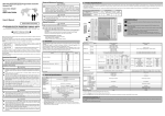
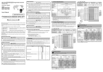
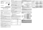
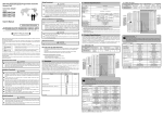
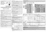
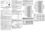
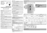
[Startup and Maintenance Precautions] Mitsubishi General-Purpose Programmable Controller Renewal Tool 3.Product Specifications WARNING Conversion Adapter Model ERNT-ASLT64AD Do not touch live terminals. There is a danger of electric shock or malfunction. Shut off the external power supply for the system in all phases before cleaning or retightening the terminal screws. Failure to do so may result in electric shock or cause the MELSEC-L Series module to fail or malfunction. Loose screws can lead to dropping, shorting, and malfunction. Excessive tightness of the screws can lead to breakage of the screws, Conversion Adapter, Mounting Bracket, or MELSEC-L Series Module, possibly causing the dropping, shorting, and malfunction thereof. User’s Manual Do not modify the Conversion Adapter or take it apart. Doing so will cause failure, malfunction, personal injury, or fire. Do not drop the Conversion Adapter and Mounting Bracket or do not give a strong impact to it. This will cause damage. [Disposal Precautions] 50CM-D180170-B(1409) HEAD OFFICE:Hulic KUDAN BLDG.1-13-5,KUDANKITA CHIYODA-KU,TOKYO 102-0073,JAPAN NAGOYA ENGINEERING OFFICE:139 SHIMOYASHIKICHO-SHIMOYASHIKI,KASUGAI,AICHI 486-0906,JAPAN SAFETY PRECAUTIONS (Always read these precautions prior to use.) *1 EMC AND LOW VOLTAGE DIRECTIVES Compliance to the EMC Directive, which is one of the EU Directives, has been a legal obligation for the products sold in European countries since 1996 as well as the Low Voltage Directive since 1997. Manufacturers who recognize their products are compliant to the EMC and Low Voltage Directives are required to declare that print a "CE mark" on their products. WARNING Indicates that incorrect handling may cause hazardous conditions, resulting in death or severe injury. CAUTION Indicates that incorrect handling may cause hazardous conditions, resulting in medium or minor injury and/or property damage. Note that failure to observe the CAUTION level instructions may lead to a serious consequence according to the circumstances. Always follow the precautions of both levels because they are important to personal safety. Please keep this manual in an easy-to-access location for future reference, and be sure to provide the manual to the end user. [Precautions before using] V+ TB1 V+ C H 1 TB1 TB2 TB3 TB4 TB5 TB6 TB7 TB8 TB9 TB10 TB11 TB12 TB13 TB14 TB15 TB16 TB17 TB18 TB19 TB20 TB2 V-/I- TB3 I+ TB6 SLD TB4 SLD TB7 V+ TB5 V+ TB8 I+ TB6 COM TB7 I+ TB10 SLD TB8 SLD TB11 V+ TB9 V+ TB9 C H 3 TB12 TB13 TB14 C H 4 TB17 TB18 *2 I+ TB10 V-/I- TB11 I+ SLD TB12 SLD V+ TB13 V+ I+ TB14 V-/I- COM TB15 I+ SLD TB16 SLD TB19 A.G TB17 AG TB20 FG TB18 FG [Wiring Precautions] WARNING Before attempting to install the Unit or carry out the necessary wiring, make certain that the external power supply, used in the system, is shut off on all three phases. Failure to do so may result in electric shock or damage to the product. After installation and wiring, close the terminal block cover before turning on the module for operation. Failure to do so may result in electric shock. CAUTION Carry out wiring for the Conversion Adapter correctly after checking the specification and terminal arrangement for the module used. Connecting a power supply with a different voltage rating or incorrect wiring may cause a fire or failure. Tighten the MELSEC-AnS Series terminal installation screws and terminal screw securely by applying torque within the specified limits. Loose screws will cause short circuit, fire or malfunction. Excessive tightening will damage the screws or the Conversion Adapter which in turn will cause dropping of parts, short circuit or malfunction. Use care to prevent foreign materials including cuttings and wiring debris from entering the Conversion Adapter or the MELSEC-L Series Module. These will be cause for fire, failure or malfunction. L60AD4 Terminal Block C H 2 C H 3 TB2 TB4 TB6 TB8 TB10 TB12 TB14 TB16 TB18 TB1 TB3 TB5 TB7 TB9 TB11 TB13 TB15 TB17 *1 L60AD4 is not provided with a terminal for Offset/Gain setting purposes. For more details about the Offset/Gain setting, see the L60AD4 User’s Manual. *2 Be sure to establish a ground for the FG terminal (TB18) of L60AD4 using the FG terminal (TB20) of A1S64AD. C H 4 1.Overview This manual describes specifications, handling and other information about the Conversion Adapter “ERNT-ASLT64AD” available as Renewal Tools for the Mitsubishi General-Purpose Programmable Controller. The Conversion Adapter is a product for effecting conversion to transcend difference in pin assignment between the MELSEC-AnS Series and the MELSEC-L Series. Before attempting to make a switch from MELSEC-AnS Series to MELSEC-L Series in your installation, consult the user's manual supplied with individual module under the latter series to learn about how they differ in various aspects including performance and function. < Specification Comparison > Model MELSEC-AnS Series A1S64AD -10 to 0 to +10VDC (input resistance:1MΩ) -20 to 0 to +20mA (input resistance:250Ω) Signed 16-bit binary 1/4000 setting:-4096 to +4095 1/8000 setting:-8192 to +8191 1/12000 setting:-12288 to +12287 Specifications Analog input Voltage Current Digital output Once you have opened the packaging, verify that it contains the following products. Product Shape Quantity Analog input 1 Mounting bracket +10V +5V or +20mA 0V or 0mA -5V or -20mA -10V I/O characteristics Mounting bracket fixing screws 1/4000 +4000 +2000 0 -2000 -4000 (M3.5 x 6) 1 Terminal block cover Voltage input Current input Maximum resolution -20480 to 20479 (When using the scaling function:-32768 to 32767) Digital output value (Gain:5V/20mA, Offset:0V/0mA) 1/8000 1/12000 +8000 +12000 +4000 +6000 0 0 -4000 -6000 -8000 -12000 This manual 1/4000 2.5mV 10μA 2.General Specifications 0 to 55℃(Maximum surrounding air temperature 55℃) -25 to 75℃ 5 to 95%RH,non-condensing Sweep count Compliant with Under 5 to 8.4Hz 10 times each in Vibration JIS B 3502 intermittent X, Y, Z directions 8.4 to 150Hz 9.8m/s2 - resistance and vibration IEC 61131-2 Under 5 to 8.4Hz - 1.75mm continuous - 8.4 to 150Hz 4.9m/s2 - vibration Compliant with JIS B 3502 and IEC 61131-2 Shock resistance (147 m/s2, 3 times each in 3 directions X, Y, Z) Operating atmosphere No corrosive gases Operating altitude *1 0 to 2000m Installation location Inside a control panel Overvoltage category *2 II or less Pollution degree *3 2 *1:Do not use or store under pressure higher than the atmospheric pressure of altitude 0m. *2:This indicates the section of the power supply to which the equipment is assumed to be connected between the public electrical power distribution network and the machinery within premises. Category II applies to equipment for which electrical power is supplied from fixed facilities. *3:This index indicates the degree to which conductive material is generated in terms of the environment in which the equipment is used. Pollution level 2 is when only non-conductive pollution occurs. A temporary conductivity caused by condensing must be expected occasionally. Number of analog input Between input terminal and programmable Isolation controller power method supply Between channels Number of occupied points Connected terminal block Current consumption Make sure the -20000 to 20000 Resolution 500μV 250μV 200μV 500μV -5000 to 22500 200μV -20000 to 20000 307μV 1000nA 800nA 0 to 20000 0 to 20000 -5000 to 22500 800nA -20000 to 20000 1230nA Ambient temperature 25±5℃:Within ±0.1% (±20digit) Ambient temperature 0 to 55℃:Within ±0.2% (±40digit) Voltage:±15V Current:±30mA 4 channels Photocoupler isolation Photocoupler isolation No isolation 32 points 20-point terminal block 0.4A No isolation 16 points 18-point terminal block 0.52A 20ms/channel Absolute maximum input Specifications Digital output value High-speed:20μs/channel Medium speed:80μs/channel Low speed:1ms/channel Voltage:±15V Current:30mA 4 channels Maximum conversion speed Constant Half acceleration amplitude - 3.5mm 1/12000 0.83mV 3.33μA Analog input range 0 to 10V 0 to 5V 1 to 5V Voltage -10 to 10V 1 to 5V (Extended mode) User range setting 0 to 20mA 4 to 20mA Current 4 to 20mA (Extended mode) User range setting 1 - Frequency 1/8000 1.25mV 5μA ±1% 1/4000 setting:±40digit 1/8000 setting:±80digit 1/12000 setting:±120digit 1 Overall accuracy Item Operating ambient temperature Storage ambient temperature Operating ambient humidity Storage ambient humidity MELSEC-L Series L60AD4 -10 to 10VDC (input resistance:1MΩ) 0 to 20mADC (input resistance:250Ω) 1 [Installation Precautions] CAUTION C H 1 V-/I- COM CAUTION Use the Conversion Adapter in the environmental conditions that are specified in the general specification. If the Products are used in any environment beyond the bounds of the general specification, electric shock, fire, malfunction, or damage to or degradation of the Products will result. Do not directly touch any conductive parts of Conversion Adapter. Contact will cause malfunction or failure in the system. Fasten the Conversion Adapter and the Mounting Bracket securely with retaining screws, and tighten the screws by applying torque within specified limits. Loose screws can lead to the dropping of the Conversion Adapter or Mounting Bracket, possibly causing breakage thereof. Excessive tightness of the screws can lead to breakage of the screws, Conversion Adapter, Mounting Bracket, or MELSEC-L Series Module, possibly causing the dropping, shorting, and malfunction thereof. Always check for correct match between MELSEC-L Series and the Conversion Adapter. Incorrect match can cause damage to the MELSEC-L Series Module. When installing the Conversion Adapter, take care not to get your hand snagged on the Mounting Bracket or the like. Injury may result. When installing or removing the MELSEC-L Series Module complete with a Converter Adapter, be sure to hold it with both hands. Dropping may lead to breakage. Precautions for wiring Signal Name I+ TB16 Authorized representative in Europe is shown below. Name: Mitsubishi Electric Europe BV Address: Gothaer strasse 8, 40880 Ratingen, Germany Terminal No. COM C H 2 75 Internal circuit diagram of ERNT-ASLT64AD TEST TB4 Conversion Adapter Weight (g) 1 TB3 TB15 Conversion Adapter When making a switch from the MELSEC-AnS Series to the MELSEC-L Series, be sure to consult user's manual supplied with individual module under the MELSEC-L Series to confirm differences in various aspects including performance, function, CPU input/output signals and buffer memory addresses between the two series. L60AD4 TB2 TB5 When disposing of the product, treat it as industrial waste. 4 After replacement MELSEC-L Series No. of Module Model modules Signal Name TEST Authorized representative in Europe Before using this product, please read this manual carefully and pay full attention to safety to ensure that the product is used correctly. The precautions presented in this manual are concerned with this product only. For Programmable Controller system safety precautions, refer to the user’s manual of the MELSEC-L series CPU module to be used. In this manual, the safety precautions are ranked as “WARNING” and “CAUTION.” A1S64AD No. of channels Terminal No. TB1 A1S64AD Terminal Block CAUTION Before replacement Conversion Adapter MELSEC-AnS Series Model Module Model ERNT-ASLT64AD CAUTION For detail specifications which do not appear in the specification comparison charts contained herein, see the user's manual supplied with the MELSEC-L Series module you use. Those parts of the specification that differ between the MELSEC-AnS Series and the MELSEC-L Series are where a switch from the first series to the second is subjected to specification-related restrictions. Check the specification of the devices to be connected for more details. Furthermore, it is recommended to refer to the “Transition from MELSEC-AnS/QnAS (Small Type) Series to L Series Handbook (Intelligent Function Modules): L (NA)-08259ENG” issued by Mitsubishi Electric. section of the above table meets the specification of the machines and equipment connected to the MELSEC-L Series module. Precautions for programming (1) L60AD4 has a greater conversion speed as compared with A1S64AD. This can make it possible for L60AD4 to pick up noise, which A1S64AD would not, as an analog signal. In such case, eliminate the effects of noise by using the average processing function that is provided. (2) A1S64AD and L60AD4 differ from each other in the way input/output signals (X, Y) and buffer memory addresses are allocated. Therefore, you need make necessary changes to the sequence program that is used. 4.Mounting and Installation 5.Part Names and Installation Method 4.1 Handling Precautions (1) Before attempting to install the Unit or carry out the necessary wiring, make certain that the external power supply, used in the system, is shut off on all three phases. Failure to do so may result in electric shock or damage to the product. (2) Do not touch live terminals. There is a danger of electric shock or malfunction. (3) Do not modify the Conversion Adapter or take it apart. Doing so will cause failure, malfunction, personal injury, or fire. (4) Do not touch the energized part of the Conversion Adapter directly. Contact will cause malfunction or failure in the system. (5) Fasten the Conversion Adapter and the Mounting bracket securely with retaining screws, and tighten the screws by applying torque within specified limits. Loose screws can lead to the dropping of the Conversion Adapter, or Mounting bracket, possibly causing breakage thereof. Excessive tightness of the screws can lead to breakage of the screws, Converter Adaptor, Mounting bracket, or MELSEC-L Series Module, possibly causing the dropping, shorting, and malfunction thereof. (6) Use care to prevent foreign materials including cuttings and wiring debris from entering the Conversion Adapter or the MELSEC-L Series Module. These will be cause for fire, failure or malfunction. (7) Do not drop the Conversion Adapter and Mounting Bracket or do not give a strong impact to it. This will cause damage. 4.2 Use Precautions Item Width dimension of module Use Precautions Because the module is reduced in width dimension (34.5mm→28.5mm) and thus in area available for wiring, check dimensional data before installing the module. <MELSEC-AnS Series> 2 Secure the mounting bracket to the MELSEC-L Series module using the mounting bracket fixing screws (M3.5 × 6). (1 place) 【Installation with the Base Adapter】 1 Position the mounting bracket to the 2 Tighten the Mounting bracket serial number display area at the bottom of the MELSEC-L Series module. Base Adapter fixing screw (M3.5×6). 4 3 (bottom) 5 Mounting bracket fixing screw M3.5×6 Mounting bracket 6 Mounting bracket (supplied with Conversion Adapter) 3 Install the Conversion Adapter to the MELSEC-L Series module, and secure it using the Conversion Adapter installation screws (M3 × 25). (1 place) Mounting bracket fixing screw M3.5×6 (supplied with Conversion Adapter) 1 Fully insert the projections on the 2 Press the Conversion adapter top of the Conversion adapter into the terminal block fixing holes. Terminal block fixing holes Conversion adapter installation screw M3×25 MELSEC-AnS Series terminal block installation screw (M4) <MELSEC-L Series> The gratis warranty period of this product shall be one (1) year from the date of purchase or delivery to the designated place. Note that after manufacture and shipment from MEE, the maximum distribution period shall be six (6) months, and the gratis warranty period after manufacturing shall be limited to eighteen (18) months. In addition, the gratis warranty period for repaired products shall not exceed the gratis warranty period established prior to repair. MELSEC-AnS Series terminal block 1 MELSEC-L Series Module Gratis Warranty Period Serial number display Conversion Adapter Precaution MELSEC-L Series System Gratis Warranty Terms and Gratis Warranty Range If any fault or defect (hereinafter referred to as “Failure”) attributable to Mitsubishi Electric Engineering Company Limited (hereinafter referred to as “MEE”) should occur within the gratis warranty period, MEE shall repair the product free of charge via the distributor from whom you made your purchase. (DIN rail portion) 2 Product Warranty Details Please confirm the following product warranty details prior to product use. Terminal block cover (supplied with Conversion Adapter) 3 Tighten the Conversion Adapter installation screw (M3×25). until it snaps into place. projections Gratis Warranty Range The gratis warranty range shall be limited to normal use based on the usage conditions, methods and environment, etc., defined by the terms and precautions, etc., given in the instruction manual, user’s manual and caution labels on the product. Warranty Period after Discontinuation of Production (1) MEE shall offer product repair services (fee applied) for seven (7) years after production of the product has been discontinued. Discontinuation of production shall be reported via distributors. (2) Product supply (including spare parts) is not possible after production has been discontinued. Exclusion of Opportunity Loss and Secondary Loss from Warranty Liability Regardless of the gratis warranty period, MEE shall not be liable for compensation for damages arising from causes not attributable to MEE, opportunity losses or lost profits incurred by the user due to Failures of MEE products, damages or secondary damages arising from special circumstances, whether foreseen or unforeseen by MEE, compensation for accidents, compensation for damages to products other than MEE products, or compensation for other work carried out by the user. 【Installation with the DIN rail】 DIN rail Changes in Product Specifications 34.5mm 28.5mm 4 The wiring may interfere with the adjacent module. Use of the Mitsubishi LG69 space module is recommended. <MELSEC-AnS Series> Precaution The specifications given in the catalogs, manuals and technical documents are subject to change without notice. Conversion Adapter Conversion Adapter installation screw M3×25 MELSEC-AnS Series terminal block <MELSEC-L Series> 1 2 Space Module LG69 16.5mm 34.5mm MELSEC-L Series System 28.5mm Installation with the Base Adapter Because the module is increased in depth dimension, check dimensional data before installing the module. MELSEC-L Conversin Adapter Base Adapter 161.3mm 51.3mmUP Installation with the DIN rail Because the module is increased in depth and height dimension, check dimensional data before installing the module. MELSEC-AnS 5.2mmUP 5.1 Installation Method Installation with the Base Adapter Installation with the DIN rail Remove the existing MELSEC-AnS Series base unit, and install the base adapter ERNT-ASLB. For how to install the base adapter, refer to the base adapter manual. Install the DIN rail on the control panel. For how to install the DIN rail, refer to the user's manual of the MELSEC-L CPU module. 1 Remove the terminal block attached with the MELSEC-L Series module after loosening the terminal block installation screw (1 place). The MELSEC-L series terminal block is not used. the terminal block installation screw. Terminal block 144.5mm MELSEC-AnS Series terminal block installation screw (M4). (2 places, top and bottom.) Terminal block cover (supplied with Conversion Adapter) Conversin Adapter 70.2mm 65mm 106mm 5 Secure the MELSEC-AnS Series terminal block to the Conversion Adapter with the supplied MELSEC-AnS Series terminal block installation screw (M4) 1 Open the terminal cover and loosen MELSEC-L 4mm 4 Install the MELSEC-L Series system to the base adapter (DIN rail portion) or the DIN rail. Conversion adapter installation screw M3×25 MELSEC-AnS 110mm 6 Mounting bracket fixing screw M3.5×6 (supplied with Conversion Adapter) 45mm Depth and Height dimension 5 Mounting bracket (supplied with Conversion Adapter) MELSEC-L Series Module Precaution Before tightening the installation screws, check that the Conversion Adapter has been securely installed on the MELSEC-L Series module. Tightening the screws in floating-off state or tilting state will damage the Conversion Adapter installation screws and the mounting bracket. 3 6 Remove the terminal block cover from the MELSEC-AnS Series terminal block and fit the terminal block cover supplied with the Conversion Adaptor in place. 5.2 Tightening Torque Tighten the installation screws to the specified torque below. An inappropriate tightening torque could cause the product to fall or result in a short circuit, product failure or malfunction. Screw Location Tightening Torque Range Mounting bracket fixing screw (M3.5×6) 0.68 to 0.92N・m Conversion Adapter installation screw (M3×25) 0.43 to 0.57N・m MELSEC-AnS Series terminal block installation screw (M4 screw) 0.78 to 1.18N・m 6.External Dimensions Unit:mm 2 Press the terminal block fixing holes until the lower part of the terminal block is disengaged from the module, and then remove the terminal block. Terminal block cover Conversion adapter Terminal block fixing holes Terminal block cover 38.5mmUP The terminal block cover for MELSEC-AnS Series is bigger than the width of the MELSEC-L Series Module. Therefore, it is necessary to replace it with the terminal block cover supplied with the converter adapter. <MELSEC-AnS Series> 102 Terminal block cover Mounting bracket <MELSEC-L Series> Terminal block cover for the MELSEC-AnS Series Terminal block installation screw Replace the terminal block cover with the one supplied with the Conversion Adapter. 28 28.5mm 4.3 Installation Environment 31.5 34.5mm The installation environment is the same as MELSEC-L series CPU Module to use. Refer to the user's manual of the MELSEC-L Series CPU Module to be used. Duplication Prohibited This manual may not be reproduced in any form, in part or in whole, without written permission from Mitsubishi Electric Engineering Company Limited. ©2014 MITSUBISHI ELECTRIC ENGINEERING COMPANY LIMITED ALL RIGHTS RESERVED MELSEC is a registered trademark of Mitsubishi Electric Corporation. This document is a new publication, effective September 2014. Specifications are subject to change without notice. Developed September 2014 50CM-D180170-B