1
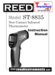
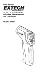
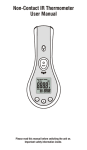
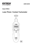
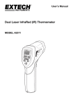
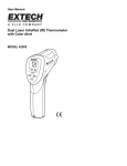
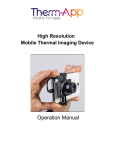
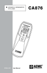
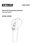
USER GUIDE IR Thermal Scanner Model IRT500 Introduction Thank you for selecting the Extech Model IRT500. The IRT500 Dual Laser IR Thermal Scanner is designed with a dual laser, an audible/visual alarm, 5 preset threshold settings, and a 3 color LED indicator that helps locate hot and cold spots more easily. This device is shipped fully tested and calibrated and, with proper use, will provide years of reliable service. Please visit our website (www.extech.com) to check for the latest version of this User Guide. The Extech Instruments brand, a wholly owned subsidiary of FLIR Systems, Inc., is ISO-9001 certified. Safety Use extreme caution when the laser pointer beam is on Do not point the beam toward anyone's eye or allow the beam to strike the eye from a reflective surface Do not use the laser near explosive gases or in other potentially explosive areas 2 IRT500-EU-EN v1.4 9/13 Meter Description 1. 2. 3. 4. 5. 6. 7. 8. 9. LCD display Red, Green, Blue limit indicator LED Momentary press: Audible Alarm ON/OFF button 2 second press: Select °C or °F button SET button: Set alarm deviation from reference value Momentary press: Laser pointer ON/OFF button 2 second press: Select MAX/MIN display button Battery compartment Power ON trigger Momentary press: Display Hold ON/OFF trigger 2 second press: Power OFF trigger Laser pointers (2) Infrared sensing window 9 1 8 2 3 4 5 7 6 1 Display Description 1. 2. 3. 4. 5. 2 3 SET and MAX/MIN display Temperature display Reference value display HOLD, Laser active, Buzzer On/Off and Low Battery icons Bargraph 3 4 5 IRT500-EU-EN v1.4 9/13 Basic Operation Basic Temperature Measurements 1. Momentarily press the trigger to turn the meter on. 2. Point the meter at an object and the surface temperature will be indicated on the display. 3. Press and Hold the trigger for 2 seconds to turn the meter off. Dual Laser Pointer and Distance to Spot Ratio The meter has a distance to target ratio of 20:1. The dual laser pointers are designed to indicate the 20” distance when the laser pointers converge. The spot size at this distance is a 1” diameter. This is the recommended distance for most measurements. To turn the lasers on/off: 1. Momentarily press the /Min-Max button 10cm @200cm 4” @80” 5cm @100cm 2” @40” 2.5cm @50cm 1” @20” 2. Repeat the press to turn the lasers off. Temperature Units °F or °C Press and Hold the °F / °C button for 2 seconds to change temperature units. Display HOLD Momentarily press the trigger to freeze the reading in the display. The “HOLD” icon will appear. Repeat the trigger press to return to normal operation. 4 IRT500-EU-EN v1.4 9/13 Thermal Scanning Operation The thermal scanning feature allows for quick and easy location of hot or cold spots with respect to a reference temperature. Hot and cold spots are readily indicated by visible and audible alarms based on a degree deviation from the reference point or by recorded MAX/MIN points. Temperature and Alarm Indicators (4) 1. Temperature readout: Large digits on the display. 2. Limit Indicator LED: Red (high), Green (normal), Blue (low) 3. Bargraph: Relative temperature indication on the display. 4. Audible Beeper: Relative temperature indication by frequency of beeps. Setting the Reference Temperature 1. Point the sensor at a surface. The initial temperature reading will become the reference temperature. 2. Momentarily press the trigger to turn the meter on. 3. When the Limit Indicator LED turns green the reference temperature has been established. The reference temperature is displayed on the bottom portion of the display. SET button The SET button sets a degree variation from the reference value to trip the Limit LED. 1. Momentarily press the SET button to display 1.0, 5.0 or 10.0 degrees. 2. If the scanned temperature is within the set limit, the limit LED will remain green. 3. If the scanned temperature is higher than the set limit, the limit LED will turn red. 4. If the scanned temperature is lower than the set limit, the limit LED will turn blue MAX-MIN button When the MAX-MIN feature is active, the upper display will indicate the highest or lowest temperature measured during a scan. Each time the existing MAX or MIN is exceeded the display will update and the limit LED will flash red or blue. 1. Momentarily press the ‘MAX/MIN’ button to display the ‘MAX’ value. 2. Repeat the press to display the ‘MIN’ value. 3. Press the ‘SET’ button to exit the ‘MAX-MIN’ mode. Beeper Momentarily press the button to enable the beeper feature. Repeat the press to disable the feature ( ). The beeper will sound approximately once per second at the reference temperature with the frequency of the beep increasing as the temperature nears the set limit or Min/Max value. 5 IRT500-EU-EN v1.4 9/13 Battery Replacement When the battery icon appears on the LCD, the 9V battery must be replaced. The battery compartment is located behind the panel below the trigger. Pull the battery compartment cover down. Replace the 9V battery. Close the battery compartment cover. EU consumers are legally bound by the Battery Ordinance to return used batteries to community collection points or to wherever batteries / accumulators are sold. Disposal in household trash or refuse is prohibited. Disposal: Follow the valid legal stipulations in respect to the disposal of the device at the end of its lifecycle. Other Battery Safety Reminders Never dispose of batteries in a fire. Batteries may explode or leak. IR Measurement Notes 1. The object under test should be larger than the spot (target) size calculated by the field of view diagram (printed on the side of the meter and in this guide). 2. Before measuring, be sure to clean surfaces that are covered with frost, oil, grime, etc. 3. If an object's surface is highly reflective, apply masking tape or flat black paint to the surface before measuring. Allow time for the paint or tape to adjust to the temperature of the surface it is covering. 4. Measurements cannot be made through glass. 5. Steam, dust, smoke, etc. can obscure measurements. 6. The meter automatically compensates for deviations in ambient temperature. However, it can take up to 30 minutes for the meter to adjust to extremely wide changes. 7. To find a hot spot, aim the meter outside the area of interest then scan across (in an up and down or side to side motion) until the hot spot is located. 6 IRT500-EU-EN v1.4 9/13 Specifications Display Backlit LCD 3-Color LED Indicator 3-color hot/cold spot LED indicator o o o LED color transitions occur at ±1 , 5 , 10 deviations from user preset ‘normal’ temperature value Response time 150 milliseconds MAX/MIN memory Display shows highest (MAX) and lowest (MIN) readings for each scan session Polarity Automatic (no indication for positive polarity); Minus (-) sign for negative polarity. Emissivity 0.95 fixed value Field of view D/S 20:1 ratio Diode Laser Output <1mW, Wavelength 630~670nm, Class 2 (II) Laser product Spectral response 8~14um Operating temperature 0 C to 50 C (32 F to 122 F) Storage temperature -20 C to 60 C (-4 F to 140 F) Relative humidity 10%~90%RH operating, <80%RH storage Power supply 9V battery, NEDA 1604A or IEC 6LR61, or equivalent Weight 5.7 oz. (163 g) Dimensions 6.6 x 3.2 x 2.3” (168 x 82 x 58 mm) Range o o o o o o o Resolution o Accuracy -30°C to 20°C -22°F to 32°F 0.1°F/°C ± 3.5°C (6.3°F) 20°C to 260°C 32°F to 500°F 0.1°F/°C ± (1% + 1.8°C or 3.3°F) Note: Accuracy is given at 18 °C to 28 °C (64 °F to 82 °F), less than 80%RH Copyright © 2013 FLIR Systems, Inc. All rights reserved including the right of reproduction in whole or in part in any form ISO-9001 Certified www.extech.com 7 IRT500-EU-EN v1.4 9/13