1
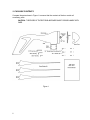
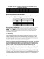
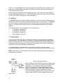
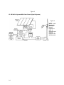
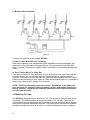
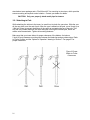
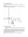
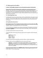
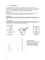
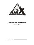
The New 400 watt turbine!
Owner’s Manual
Version 3.2
NOTICES:
•
This information is believed to be reliable; however, Southwest Windpower, Inc.
assumes no responsibility for inaccuracies or omissions. The user of this information
and product assumes full responsibility and risk.
•
All specifications are subject to change without notice.
•
Wind generators, like other sources of electrical power, must be installed following the
guidelines established by state and local regulations. Consult a local electrical contractor for
details and regulations.
Made in the USA by:
Southwest Windpower, Inc.
2131 N. First Street
Flagstaff, Arizona 86004
Toll Free Phone: (800) 946-3313
Phone: (520) 779-9463
Fax: (520) 779-1485
E-mail: [email protected]
Web: www.windenergy.com
AIR, AIR 403, and AIR Wind Module are trademarks of Southwest Windpower
1999 Southwest Windpower, Inc.
2
CONGRATULATIONS!
You have just purchased the most advanced battery charging wind turbine in the world!
We believe you will find it easy to install your AIR 403; however, it is important that you read
this entire manual thoroughly prior to installation to assure proper performance and safety.
Southwest Windpower has over 12 years of experience in designing and manufacturing
small wind generators. In just four years, over 20,000 AIRs have been sold throughout the
world.
What makes the AIR 403 unique in comparison to other turbines is the use of state-of-the-art
technology like Iron Boron Neodymium magnets, carbon reinforced engineering
thermoplastics, high-quality aluminum, stainless steel hardware and integrated electronics.
The turbines come standard with built-in regulators, self-governing mechanisms and the best
global warranty program in the industry.
The AIR 403 is for use in applications where salt corrosion is not expected to be a concern.
The AIR marine is designed for offshore and or land-based coastal applications.
If you have any questions after thoroughly reading the manual, please contact your
authorized distributor/dealer or Southwest Windpower, Inc.
Enjoy.
3
New Features of the AIR 403
•
•
•
•
•
4
Hysteresis: The AIR 403 regulation control circuitry now incorporates hysteresis. This
will lock the turbine in a silent regulation mode once the batteries are fully charged. The
turbine begins producing power again when it senses the battery voltage slightly below
fully charged. This means, for a factory set 12V turbine, the turbine will regulate (shut
down) when the batteries have reached 14.1V, and will resume charging when the
voltage drops to 12.6V, which is slightly below fully charged. Minimal output is wasted,
as non-charging battery voltages above 12.6V represent mostly a “surface charge” with
very little energy. This feature prevents the turbine from fluctuating in and out of regulation
mode, resulting in a quieter, better-behaved machine.
New Electronics: The AIR 403 incorporates an exclusive power rectifier that sinks
excess heat directly to the body. The regulation electronics have been enhanced for
more robust control and reliability in the most extreme operating conditions.
New Alternator: A more powerful alternator has been built into the new AIR 403. The
stronger permanent magnet rotor can be felt in rotating the blade shaft; a slight “catch”
can be felt when spinning the shaft with your fingers. This is normal, and is quickly
overcome when the blades begin spinning.
New Blades: The rotor blades have been redesigned with a new, highly efficient true
airfoil. An all-new precision injection mold produces blades of exceptional consistency,
resulting in quieter performance and minimal vibration. In high winds the enhanced overspeed mode (“flutter”) drops power output and machine RPM for longer life, lower noise,
and even greater survivability in the harshest winds.
New Body, New Hub: The AIR 403 body is made from a precision casting process that
not only enhances fit and finish, but also leads to a stiffer, more durable body. The die
cast aluminum hub design has been engineered to be the strongest, stiffest hub we have
ever produced.
Table of Contents
1. Safety Precautions………………………………………………………...
1.1 Mechanical Hazards
6
6
1.2 Electrical Hazards
1.3 Installation
1.4 Operation
2. Package Contents…………………………………………………………
3. Wiring and Installation Procedures…………………………………….
3.1 Wiring…………………………………………………………………..
3.1.1 Electrical Connections
9
3.1.2 Wire Size
3.1.3 Grounding
11
3.1.4 Fusing
12
3.1.5 Stop Switch
12
3.1.6 System Wiring Diagrams
6
7
7
8
9
9
10
13
3.2 Mounting to Tower……………………………………………………15
3.2.1 Attaching to Pole
16
3.3 Hub and Rotor Assembly……………………………………………
17
3.3.1 Mounting Blades
17
3.3.2 Mounting Hub and Rotor
18
3.3.3 Attaching Nose Cone
18
3.4 Step By Step Instructions…………………………………………..
18
4. Testing……………………………………………………………………….
20
4.1 General Discussion of Operation………………………………….
20
4.1.1 Alternator
20
4.1.2 Regulator
20
4.1.3 Blades
20
4.1.4 Four Spinning Conditions
21
4.2 Bench Testing…………………………………………………………
21
4.3 Performance Testing…………………………………………………
22
4.4 Adjusting the Internal Regulator…………………………………..
22
5. Trouble Shooting…………………………………………………………..
23
5.1 Assembly……………………………………………………………….
23
5.2 Electrical System………………………………….………………….
23
5.3 Elevation………………………………….………………...………….
24
6. Warranty Policy…………………………………………………………….
25
7. Specifications………………………………………………………………
26
7.1 Technical Specifications
26
7.2 Sphere of Operation
27
7.3 Exploded View of AIR 403
27
8. Maintenance………………………………………………………………...
28
9. System Requirements and Considerations……………………………28
9.1 Batteries
28
9.2 Regulator Options
29
10. Siting………………………………………………………………………..
30
11. Towers………………………………………………………………………33
11.1 Guyed Towers
33
11.2 Roof Top Mounting
33
12. Frequently Asked Questions…………………………………………...
35
13. Accessories………………………………………………………………..
38
14. References
…………………………………………………………………39
5
1. SAFETY PRECAUTIONS
The AIR 403 has been designed with your safety in mind. However, there are inherent
dangers involved with any electrical and/or mechanical equipment.
Safety must be the primary concern as you plan the location, installation and
operation of the turbine. At all times be aware of electrical, mechanical and rotor
blade hazards.
1.1 Mechanical Hazard
Rotating blades present the most serious mechanical hazard. The AIR 403’s rotor blades are
made of very strong thermoplastic. At the tip, the blades may be moving at velocities over 300
miles per hour. At this speed, the tip of a blade is nearly invisible and can cause serious
injury. Under no circumstances should you install the turbine where a person could
come in contact with moving rotor blades.
CAUTION: DO NOT INSTALL THE TURBINE WHERE ANYONE CAN APPROACH
PATH OF THE BLADES.
THE
1.2 Electrical Hazards
The AIR 403 is equipped with sophisticated electronics designed to provide protection from
electrical dangers. The internal electronics of the AIR 403 prevent open circuit voltages from
rising above 23 volts for 12-volt systems or above 45 volts for 24-volt systems.
Heat in wiring systems is often a result of too much current flowing through an undersized
wire or through a bad connection. It is important to follow the wire-sizing chart in Section
3.1.2 on page 10 to insure a safe electrical system.
CAUTION: FOLLOW THE WIRE SIZING CHART IN SECTION 3.1.2 ON PAGE 10 TO
HELP AVOID THE RISK OF AN ELECTRICAL FIRE.
Batteries can deliver a dangerous amount of current. If a short occurs in the wiring from the
batteries, a fire can result. In order to avoid this threat, a properly sized fuse or circuit breaker
is required in the lines connecting to the battery. Refer to Section 3.1.4 on page 12 for fuse
sizing information.
CAUTION: FUSE ALL CONNECTIONS. FOLLOW THE FUSE SIZING GUIDELINES IN
SECTION 3.1.4 ON PAGE 12 TO MINIMIZE THE RISK OF AN ELECTRICAL FAILURE.
6
1.3 Installation
CAUTION: INSTALLATION PROCEDURES SHOULD BE PERFORMED AT GROUND
LEVEL.
CAUTION: MAKE SURE THAT ALL BATTERIES ARE DISCONNECTED THROUGHOUT
THE INSTALLATION PROCESS.
CAUTION: NEVER INSTALL THE AIR 403 UPSIDE DOWN.
Please follow these precautions during the installation process:
•
Choose a calm day.
•
THINK SAFETY! Have someone available to help during the installation process.
•
Disconnect batteries from turbine wiring.
•
Prior to attaching the wires to the battery, tie the wind turbine output lead wires
(positive = red; negative = black) together near the battery to be sure that the rotor will not
spin-up during installation.
NOTE: Do not install the blade assembly until the turbine is mounted on the tower.
1.4 Operation
Check support structures, blades, and electrical systems on a regular basis.
•
The rotor blades are very strong; however, if they come in contact with a solid object,
they can break. Use common sense about safety when locating the turbine.
•
When performing periodic inspections, or at anytime when you must approach the
path of the blades, disconnect the power leads from the battery and tie the wind turbine
output leads together to stop (slow down) the blades from rotating. The turbine can also be
shut down through the use of a stop switch. Please refer to Figure 2 on page 13 on how to
install a stop switch in your system.
CAUTION: NEVER APPROACH THE TURBINE DURING OPERATION.
USE COMMON SENSE AND PLEASE BE CAREFUL
7
2. PACKAGE CONTENTS
Compare the parts shown in Figure 1 to ensure that the contents of the box contain all
necessary parts.
CAUTION: THE EDGES OF THE ROTOR BLADES ARE SHARP. PLEASE HANDLE WITH
CARE.
Figure 1
8
3. WIRING AND INSTALLATION PROCEDURES
Your AIR 403 is shipped partially disassembled. Refer to Figure 7 on page 17 for assembly
instructions. Please completely read all procedures before beginning installation.
NOTE: Do not install the blade assembly until the turbine is mounted on the tower.
Required Tools:
•
5/16” hex key wrench (included)
•
3/16” hex key wrench (included)
•
5/32” hex key wrench (included)
•
Torque wrench with 5/16”, 3/16”, and 5/32” hex drives (optional)
•
Soldering iron or propane torch
•
Rosin core solder
•
Electrical tape or 1/4” (6-7mm) heat shrink
•
Wire strippers
•
Wire crimpers
3.1 Wiring
3.1.1 Electrical Connections
NOTE: Refer To All Local and National Codes Before Installation.
CAUTION: MAKE SURE THE TURBINE IS DISCONNECTED FROM THE BATTERIES
DURING INSTALLATION.
Avoid connecting different metals together (i.e., copper and aluminum). This will cause a
galvanic cell that will erode one of the metals. When such connections can not be avoided,
consult your dealer or an electrical supply house for anti-oxidant compounds. If possible
solder wire termination ends.
CAUTION: CONNECTIONS SHOULD BE INSPECTED PERIODICALLY FOR SIGNS OF
CORROSION AND CLEANED WHEN NECESSARY.
NOTE: All electrical power cables should be physically protected. Run the wires inside the
tower or conduit for maximum protection.
NOTE: The yaw can support a total of 150 lbs. (68 kg) in wire weight. For higher wire
weights, you must install a strain relief to minimize the stress put on the hanging wires.
Wire Color Codes
RED = positive
BLACK = negative
GREEN = earth ground
9
3.1.2 Wire Size
To select the appropriate size wire, measure the distance from the batteries to your AIR 403,
then refer to the following wire sizing chart as minimum sizes. If cost is not an issue, a larger
sized wire will improve the performance of your AIR.
All electrical systems lose energy from the resistance of the wires used. Larger wiring sizes
have smaller losses, but can be considerably more costly. The following wiring sizes provide
a maximum annual energy losses of 5% or less for sites with a 12mph average wind speed
(assuming the standard Rayleigh distribution of wind speeds,) which is sufficient for most
sites. If you know your average wind speed to be different, compensate the wiring
LENGTHS given in the charts using the factors given at the end of this section. Table entries
with a “*” denote cases which should use additional bus lines.
We recommend these as the minimal wire sizes; for optimal performance you should use the
largest wires that are practical and affordable. Local, state, and national electrical codes
supercede these recommendations, and should be followed to insure the safety of your
system.
12V AIR 403: Wire Size, Considering 12mph Wind Average and 95% Energy
Transmission Efficiency
# Turbines 0-30ft
31ft-60ft
61ft-90ft
91ft-150ft
151ft-190ft 191ft-250ft 251ft-310ft 311ft-390ft 391ft-500ft
1
8g
6g
4g
2g
1g
0g
00g
000g
000g
2
6g
4g
1g
00g
000g
0000g *
*
*
3
4g
2g
0g
000g
0000g *
*
*
*
Fuse: 100 Amp Slow-Blow per turbine
* If your system requires this length of wire, consider using additional bus line(s).
24V AIR 403: Wire Size, Considering 12mph Wind Average and 95% Energy
Transmission Efficiency
# Turbines 0-30ft
31ft-60ft
61ft-90ft
91ft-150ft
1
14g
12g
10g
8g
2
12g
8g
6g
4g
3
10g
8g
6g
4g
Fuse: 50 Amp Slow-Blow per turbine
151ft-190ft 191ft-250ft 251ft-310ft 311ft-390ft 391ft-500ft
6g
4g
2g
4g
2g
2g
4g
2g
1g
4g
1g
0g
2g
0g
00g
36V AIR 403: Wire Size, Considering 12mph Wind Average and 95% Energy
Transmission Efficiency
# Turbines 0-30ft
31ft-60ft
61ft-90ft
91ft-150ft
1
14g
14g
12g
10g
2
14g
12g
10g
8g
3
14g
10g
8g
6g
Fuse: 35 Amp Slow-Blow per turbine
10
151ft-190ft 191ft-250ft 251ft-310ft 311ft-390ft 391ft-500ft
10g
8g
6g
8g
6g
4g
8g
6g
4g
6g
4g
2g
6g
4g
2g
48V AIR 403: Wire Size, Considering 12mph Wind Average and 95% Energy
Transmission Efficiency
# Turbines 0-30ft
31ft-60ft
61ft-90ft
91ft-150ft
1
14g
14g
14g
14g
2
14g
14g
12g
10g
3
14g
14g
12g
10g
Fuse: 25 Amp Slow-Blow per turbine
151ft-190ft 191ft-250ft 251ft-310ft 311ft-390ft 391ft-500ft
12g
10g
8g
10g
8g
8g
10g
8g
6g
10g
6g
6g
8g
6g
4g
Wiring Compensation for Average Wind Speed
For different average wind speeds, the wire LENGTHS in the charts should be compensated.
Compensating by changing wire gauge can lead to safety problems. For the average wind
speed of your site, multiply each wire length in the chart by the factor shown:
Average Wind Speed
9mph
10mph
11mph
12mph
13mph
14mph
Multiplier for Wire LENGTHS
2
1.5
1.25
1
0.8
0.6
Wiring Resistance and Regulation
Wiring resistance can affect the regulation set point of the turbine. Higher wiring resistance
(smaller wires) will lower the voltage at which the turbine enters regulation and stops
charging. The recommended wiring sizes should provide little effect on the regulation set
point, but all installations should be observed over time to ensure that the batteries are
charged to the proper voltage.
3.1.3 Grounding
Properly grounding the turbine is very important in protecting the electronics for long-term
operation. Grounding procedures must be followed along with any local electrical codes.
IMPORTANT: SEVERE TURBINE DAMAGE CAN RESULT FROM IMPROPER GROUNDING!
FAILURE TO PROPERLY GROUND WILL VOID YOUR WARRANTY.
It is very important to ground your battery bank and ground your tower for lightning and static
protection. The green lead wire provides grounding for the body of the turbine. This wire must
be connected to the system earth ground. This is usually done by connecting a wire from a
ground rod near the base of the tower to the green turbine lead wire. For additional lightning
and static protection, another wire should connect this ground rod to the tower pipe.
The negative wire of your system should also be connected to a ground. This is usually done
by connecting a wire from the negative battery terminal to a nearby ground rod. Wires with
the same ratings as the positive and negative wires must connect all system grounds (see
Wire Size Section 3.1.2).
A ground electrode can be made for systems without an existing system ground from an 8 ft.
(2.4 m) section of 3/4" (19 mm) galvanized pipe or conduit, or an 8 ft. (2.4 m) section of 5/8"
(16 mm) iron or steel rod. This ground electrode must be buried completely beneath the soil, at
no more than 45 degrees from vertical, or horizontally at least 2 1/2 ft. (75 cm) beneath the
11
surface. It is recommended that the ground electrode be installed as close as possible to the
batteries for maximum lightning protection. The base of the tower is also a good location for
an appropriate surge arrestor.
Delta manufactures surge arrestors for lightning protection, such as their model LA 302-RG.
Contact: Delta Lighting Arrestors P.O. Box 750, Big Springs TX 79721, Phone (915) 267-1000
Fax (915) 267-1035 or your dealer for more information.
3.1.4 Fusing
The AIR 403 is capable of producing high amperages. As with all electrical installations, you
must protect each of your turbines with a properly sized fuse or circuit breaker. The AIR 403
should be wired with an appropriately sized “slow-blow” type fuse between itself and the
batteries. If a stop switch is used, the fuse should be placed between the switch and the
batteries.
Recommended Size for Circuit Breakers or Slow-Blow Fuses
•
12-volt model: 100 amps D.C.
•
24-volt model: 50 amps D.C.
•
36-volt model: 35 amps D.C.
•
48-volt model: 25 amps D.C.
3.1.5 Stop Switch
A stop switch must be used with your AIR 403 to provide a convenient method for shutting
down the turbine. The stop switch is a 50-amp D.C. single-pole double-throw switch that is
used to shut the turbine off. The switch disconnects the battery and then shorts the turbine
causing the turbine to stop spinning (in high winds the blades will spin slowly). Shorting the
turbine will not cause any damage or additional wear.
Your dealer/distributor should be able to supply the stop switch or you can contact
Southwest Windpower directly. They can also be found at some automotive electrical stores.
NOTE: The center post must be positive from the turbine. Outside posts can be swapped as
either positive or negative.
Figure 2 Stop Switch Wiring
Some installations of the AIR 403 may require a high current
rated stop switch, such as 12V systems in very high wind
applications, or in cases where local electrical codes
require it. Switches used in these applications must be
single-pole, double-throw, rated for the maximum voltages
and currents that the system may experience. Many
battery bank selector switches for RV’s can NOT be used,
as they include a “BOTH” position, which will short your
battery bank.
12
High current switches are more costly, but there are some reasonably priced, quality
switches available from industrial supply stores. One good choice is a battery selector
switch manufactured by Cole-Hersee, model number 75502. This switch is available from
several sources, including Specialty Electric Supply in Homer, AK, phone # (907) 235-9020,
and also from Industrial Sales and Service in Portland, OR, phone # (503) 239-0754.
To use this switch, connections are the same as the switch described above, with the
“Battery 1” post to the battery positive, the “Battery 2” post to the turbine/battery negative,
and the third post to the turbine positive.
3.1.6 System Wiring Diagrams
Before deciding how to wire your AIR 403 it is important to understand how your existing
system is wired and how the AIR 403’s internal regulator operates. Refer to the General
Discussion of Operation in Section 4.1.2 on page 20 for information on the AIR 403’s internal
regulator.
The recommended way to connect the turbine to your battery bank is to wire the turbine
directly to the battery bank to its own set of battery posts. This will allow the turbine to
operate independently. The AIR 403’s internal regulator will independently monitor the battery
and charge as necessary.
You can wire the AIR 403 through most “power centers”. However, if you experience
interference or pre-regulation, you must bypass it and wire the turbine directly to the battery
bank.
Some external charging sources (i.e. solar panels, fuel-powered generators, additional wind
generators etc.) can interfere with the turbines electronics and cause pre-regulation. If there
is external interference, it will not harm the turbine: it will just cause the turbine to spin slowly
as if “braked” or in the stop position. If this occurs test the possible interference by
disconnecting the other charge sources to determine the possible interference source.
Choose the appropriate wiring diagram below for proper wiring information.
A. Single AIR 403 Wiring
Figure 3
13
Figure 3
B. AIR 403 In System With Solar Panels (Hybrid System)
Figure 4
NOTE: In this
drawing the
AIR 403’s
internal
regulator is
used. A
diversion type
external
regulator can
also be used.
14
C. Multiple AIR Installation
Figure 5
There are two methods to wire multiple AIR 403s.
a) Each Turbine Wired Directly To Battery
Each turbine operates as an independent system separate from other solar panels, gas
generators or any other battery charging sources. If the turbine has its own fuse, stop
switch (optional), and wires, the turbine is able to individually communicate and charge the
battery.
b) Each Turbine Wired To A Bus Bar
If you plan to wire two or more turbines to a “bus”, and then run one set of wires from the
bus to the battery, you can use each turbine’s internal regulator or install an external
regulator. If you use an external regulator use a diversion style regulator that turns excess
power into heat for heating a room, water etc. When wiring multiple turbines, it is possible to
reduce your wiring costs by using a bus bar system.
NOTE: Do NOT accidentally connect the turbine “backwards” to the battery for
even a second (i.e. turbine positive to battery negative and turbine negative to
battery positive). Doing this will instantly destroy the circuit inside the turbine
and void your warranty.
3.2 Mounting To Tower
The AIR 403 is designed to be mounted on a 1 1/2“, SCH 40 steel or aluminum pipe (do not
use plastic). The outside diameter of the pipe should be 1.875” (48 mm). There is a soft
coupling inside the yaw shaft mount that is designed to provide a secure fit and to dampen
some of the noise transmitted down the tower. The pole must be mounted with hardware
specifically designed for small wind turbines. Southwest Windpower offers a complete
15
stand-alone tower package and a “Roof Mount Kit” for mounting to structures, which provides
secure mounting and superior noise isolation. Contact your dealer for details.
CAUTION: Only use properly sized metal pipe for towers.
3.2.1 Attaching to Pole
While attaching the turbine to the tower, be careful not to pinch the yaw wires. Slide the yaw
all the way down over the end of pole. After the yaw is seated on the pole, move it back up a
1/8th inch (2mm) to prevent the bottom of the yaw from contacting the top of the pole. This
way the only contact between the tower and yaw is through the rubber pad, which will
reduce noise transmission. Tighten all mounting fasteners.
Make sure that your tower allows for proper clearance of the blades. A minimum
2 inch (20 mm) clearance must be given between the blade tips and any obstructions. Refer
to Figure 6 below, and the “Sphere of Operation” drawing in Section 7.2 on page 27 for
proper clearances.
Figure 6 Proper
Blade-to-Tower
Clearances
16
3.3 Hub And Rotor Assembly
Before assembling the hub and rotor refer to Figure 7 below, and the following detailed
instructions.
NOTE: To avoid damage to the blades during installation, do not put the blade assembly on the
turbine until the turbine is mounted on the tower.
Figure 7
3.3.1 Mounting the Blades
CAUTION: THE EDGES OF THE ROTOR BLADES ARE SHARP. PLEASE HANDLE WITH
CARE.
Notice that the screw holes in the blades are counter-bored for the socket head cap screws.
Place one of the blades with the counter bore facing up, and align the screw holes. Insert one
of the socket head cap screws through the blades and hub. Place a nut on the end of the
screw and tighten the screw with the 3/16” hex key wrench to 10 – 12 foot lbs. (13.6 – 16.3
Nm). Repeat this procedure on all three blades.
NOTE: You may need to “thread” the screws through the hub with the hex wrench.
17
3.3.2 Mounting the Hub and Rotor
CAUTION: THE BLADES ARE SHARP. USE CAUTION WHILE HANDLING THE BLADES.
Remove the 5/8” nut from the alternator shaft. Carefully slide the blade assembly onto the
alternator shaft. Place the nut on the shaft and thread the nut on by spinning the blade
assembly. Insert the 5/16” hex key torque wrench into the alternator shaft and tighten the nut
by holding the hub set and tightening the shaft with the torque wrench. The nut should be
tightened to 50 - 65 foot pounds (68 – 88 Nm). When the blade set assembly is tightened, spin
it to be sure it turns freely.
3.3.3 Attaching Nose Cone
Carefully place the nose cone over the center of the hub and the blades. Snap the nose cone
into place. Be sure all three edges catch. Check to see that the nose cone is secure by firmly
pulling on it. The nose cone does not affect the performance of the turbine and may be left
off, if desired.
3.4 Step By Step Instructions
The following Step-By-Step-Installation-Procedures provides you with an outline of the AIR
403 installation process. This consolidated reference should only be used as an outline during
installation. Refer to the appropriate sections for further details.
1) Run the wires from the battery (do not connect to the battery), through the pole to the top
of the tower. Be sure not to connect the wires to the battery until everything else
has been completed.
2) Strip the insulation back from each set of wires.
3) Mark both ends of all the wires with tape to identify which is negative, positive and earth
ground.
AIR 403 color-codes:
RED = Positive
BLACK = Negative
GREEN = Ground.
4) Insulate the connections using either heat shrink tubing or a quality electrical tape.
5) Connect the wires from the AIR 403 to the wires running to the battery.
CAUTION: IF THE WIRES ARE HOOKED-UP BACKWARDS YOU WILL DAMAGE THE
AIR 403’S ELECTRONICS. (IF YOU ARE UNCERTAIN OF THE POLARITY OF THE
WIRES, SIMPLY SPIN THE ROTOR SHAFT AND MEASURE THE VOLTAGE DIRECTION
WITH A VOLT METER).
6) Once the wires are attached to the AIR 403, gently pull the wires down through the tower
sliding the yaw shaft over the 1 1/2“, Schedule 40 steel or aluminum pipe (Actual OD 1.875
inches, 48mm). Do not use plastic pipe.
18
7) Slide the yaw shaft all the way down over the end of pole being careful not to pinch the
yaw wires. Be sure to leave enough slack in the wires so that if necessary, the turbine can
be removed.
8) After the yaw is all the way onto the pole, move it back up 1/8th inch (2 mm) to prevent the
bottom of the yaw from contacting the top of the pole. The only contact between the tower
and yaw is through the rubber pad which will reduce the transmission of noise down the
tower.
9) Once the yaw shaft is on the tower, firmly tighten the yaw clamp screws with the 5/32
hex key. The AIR 403 should yaw freely without restrictions.
10) Check your AIR 403 to be sure that it is securely attached to the mounts. Remember that
this attachment will have to hold in high winds.
11) Attach the assembled hub and blades to the rotor shaft.
12) Run all wires from the turbine to the battery (do not connect wires to the battery). Be sure
to crimp and solder the connections using the appropriate sized connectors. If you plan to
connect an amp meter into your system, see Figure 4, on page 14.
13) Attach your positive (RED) wire to a fuse. Refer to Section 3.1.4 for fusing information.
14) Make sure that your system is properly grounded before proceeding. Refer to the
Grounding Section 3.1.3 on page 11.
IMPORTANT: SEVERE UNIT DAMAGE WILL RESULT FROM IMPROPER GROUNDING.
FAILURE TO PROPERLY GROUND THE TURBINE WILL VOID YOUR WARRANTY.
15) Before attaching the wiring to the battery, make sure that:
- all circuit breakers are in the off position
- the stop switch is in the “stop” or shorted position (if installed)
16) Attach wires to the battery. Red wire to positive, Black wire to Negative.
17) Turn on the circuit breakers and or stop switch.
18) When the blades are rotating very quickly in the wind, you should see the red LED
illuminate.
19) You have now completed the installation process.
19
4. TESTING
4.1 General Discussion of Operation
The available energy in the wind is the cube of the wind speed. This means that each time
you double the wind speed you get eight times the power. The unique design of the AIR 403
is such that it can take full advantage of the power in the wind. The efficiencies of other wind
turbines are usually linear and can not take advantage of the cube effect of the wind. These
turbines are efficient at only one or two points along the power curve. The AIR 403’s
efficiency curve matches the available energy in the wind making it efficient all along the
curve. This is an important reason why the AIR 403 is able to provide you with such a large
amount of power from a small turbine.
4.1.1 Alternator
The AIR 403 uses a three-phase brushless permanent magnet alternator that internally
rectifies the power to D.C. The rotor is comprised of 12 Neodymium Iron Boron arced
magnets, the most powerful magnet material available. The stator is hand wound for
maximum output.
4.1.2 Regulator
When the battery voltage matches the regulation set point the turbine will “shut off”. The new
403 includes the new Autobreak™ electronics which now “stop” the blades to a slow, silent
spin when the batteries are full.
Normal charging will resume when the battery voltage drops slightly below the fully charged
level. For 12v turbines the turbine will resume charging at 12.6v (25.2 for 24v turbines).
NOTE: Bad connections, undersized wires, and inline diodes will cause the internal regulator
to not work properly. It is very important that the AIR 403 can “sense” the proper battery
voltage.
4.1.3 Blades
The blades consist of an injection-molded high strength all carbon fiber reinforced engineering
thermoplastic that results in strong lightweight blades. The blades are computer designed to
efficiently extract the most power out of the wind. The blade design also provides “overspeed” protection in high winds. All wind generators need some type of high wind overspeed protection. The AIR 403’s blades feature aeroelastic twist. In winds moving above
approximately 40-mph (17.9 m/s), the blade tips will “dump” excess wind off and prevent the
turbine from over-speeding. The benefit is that the turbine is able to maintain output, providing
you with the most possible power. It also reduces the number of parts, resulting in increased
reliability. The only disadvantage of this type of governor is that in high winds the turbine may
produce a loud noise. Other turbines have complex mechanisms that either mechanically
break the turbine or turn it out of the wind. This can reduce reliability due to increased
complexity, and reduce output by as much as 90%.
4.1.4 Four Spinning Conditions of the AIR 403
a) Open Circuit
20
When the turbine is disconnected from the batteries, it will “free-spin”. In this mode the
generator can spin “unloaded” with the wind. At approximately 40-mph (17.9 m/s) wind
speed, the blades will begin to go into an aeroelastic stall to prevent the rotor from overspeeding. In addition, the internal regulator has a high-speed regulation to protect the circuit
from high voltage conditions.
Operating the turbine in open circuit for a brief period of time will not damage the turbine.
However, operating the turbine in open circuit for a long period of time can cause excessive
wear to the turbine and is NOT recommended. We recommend that during long periods of
operation the turbine should be connected to a battery or the turbine wires should be shorted.
Shorting the turbine will minimize wear to the bearings and prolong turbine life and is quieter
than running open circuit.
b) Normal Operation (Charge)
When the generator is connected to a battery bank in need of a charge, the turbine blades will
spin “normally” with the wind. The turbine will charge the battery bank as necessary until the
battery voltage matches the regulation set point.
NOTE: When switched from open circuit to charge, you may notice a reduction in RPM as the
generator is now “under load”. If the batteries are fully charged the turbine blades will slow to
a silent spin.
c) Regulation
When the battery voltage matches the regulation set point, the turbine will go into ”regulation”.
Blade RPM will lower dramatically and output will stop. (In very high winds there may still be a
trickle charge.) Normal charging operation will resume when the battery voltage drops slightly
below the fully charged level. This regulation feature called Hysteresis is explained in more
detail in the New Features section (see page 4).
d) Braking
Braking can be accomplished by directly shorting the turbine negative and positive wires or
through the use of a Stop Switch. The Stop Switch will disconnect the turbine from the
battery, and then short the positive and negative leads from the generator together.
The blades could still spin slowly but will not charge the battery.
4.2 Bench Testing
Two quick bench tests can verify if your AIR 403 is providing output.
Test 1
1. Remove blade assembly from turbine and place in a safe location. (Do not stand the blade
assembly against a wall.)
2. Spin rotor shaft with your fingers or the allen wrench provided while at the same time
connecting and disconnecting the Red and Black yaw wires.
3. With the yaw wires connected, the rotor shaft should become more difficult to rotate and
feel “lumpy”. With the yaw wires disconnected it should spin freely. If these conditions do not
exist, you should contact your turbine dealer or Southwest Windpower.
Test 2
1. Remove blade assembly from turbine and place in a safe location. (Do not stand the blade
assembly against a wall.)
21
2. Connect a voltmeter across the Red and Black yaw wires.
3. With a 5/16” hex drive in an electric drill, spin the rotor shaft while observing the voltmeter.
(Cut a small piece off of the Hex Key provided if necessary.)
4. Rated voltage should be achieved at a minimum of 950 RPM.
NOTE: Do not be alarmed if the open circuit voltage goes above the regulation set point
voltage. The open circuit voltage will not change if you adjust the regulation set point. DO
NOT adjust the regulation set point in an attempt to alter the open circuit voltage. Changing the
regulation set point will have no affect on the open circuit voltage.
4.3 Performance Test
1. Isolate the turbine from the system.
Connect red positive turbine wire to the battery positive post. Connect the black
negative turbine wire to the negative battery post. Make sure no other system
charging components are connected. Also, make sure that switches, diodes,
regulators or meters are not connected.
2. Connect amp meter.
Connect your non-averaging amp meter in-line the positive (red) wire according to the
manufacturer’s recommendations.
3. Monitor wind speed vs. output
Record the data and compare to the power curve. Use an anemometer located within
5 feet (1.5 m) of the turbine to get accurate wind speed information. An anemometer
located in a higher location will not provide correct information for power curve
assessment. Also refer to the elevation vs. output chart in Section 5.3 on Page 24 for
information on elevations effect on output. Small differences in the wind can have
substantial effects on output.
4. Check results
If the turbine has very poor or no output when compared to power curve, refer to the
Trouble Shooting section.
4.4 Adjusting the Internal Regulator
It is important to understand how to use the AIR 403’s internal electronics to ensure proper
charging of your batteries. Refer to Figure 7 on page 17 for the location of the regulator
adjusting screw. In the following paragraphs 24-volt settings are in Italics.
The voltage regulator is factory set at 14.1 (28.2) volts. The factory setting is marked on the
casting with a small indentation aligned with the screw slot.
To change the setting on the voltage regulator, rotate the adjusting screw 1/8 of a turn for
each 0.7 (1.4) volts change desired. For example, if you want to set your voltage regulator to
14.8 (29.6) volts, turn the adjusting screw clockwise by 1/8 turn, from the 14.1 (28.2) volt
setting.
The adjustment screw will provide regulation settings for voltage ranges at least as wide as
those listed below. The actual voltage set point at the extreme counter-clockwise position
22
may be as much as 10% lower than the value listed, and at the extreme clockwise position
may be up to 10% higher than the value listed.
AIR Adjustable Voltage Range
12v
13.8v to 17.8v
preset to 14.1v
24v
27.6v to 35.6v
preset to 28.2v
36v
41.4v to 53.4v
preset to 42.3v
48v
55.2v to 71.2v
preset to 56.4v
READ THIS BEFORE YOU CONSIDER ADJUSTING THE REGULATION SETPOINT
Turning “up” the regulation set point adjustment will NOT increase the AIR 403’s output
voltage or amperage. It simply adjusts the “shut down” point for the generators’ voltage
regulator. When the battery voltage reaches the regulation set point voltage, the turbine will
slow down and stop charging the batteries. Turning the screw completely clockwise will
NOT increase the voltage or power output and will only increase the probability of
overcharging your batteries.
5. TROUBLE SHOOTING
If the turbine does not work properly after following the installation instructions, then read this
chapter and carefully compare your installation with each section.
5.1 Assembly
Make sure the blade assembly is on tight. You can check by placing the 5/16” hex key in the
shaft, holding it and attempting to turn the blade assembly. If you can turn the blade, retighten
the blade assembly.
To minimize noise, make sure that you have loosened the four mounting screws and moved
the turbine up 1/8” inch (2mm) and then re-tighten the screws. This will prevent the top of the
pole from touching the hard plastic in the yaw shaft assembly.
5.2 Electrical System
Your battery bank should be a minimum 400 amp hours for 12v systems, and 200 amp hours
for 24v system. If your battery bank is smaller than the recommended size, battery voltage
could quickly rise while the turbine is charging and cause the internal regulator to prematurely
stop charging. The AIR 403’s trickle charge could potentially over-charge the smaller battery.
Measure the voltage at the battery terminals to which the AIR 403 is connected. For the
factory regulation set point, if the voltage for a 12v system reads 14.1 or higher
(24v 28.2), then the turbine will sense the battery is charged and stop producing
power. (In high winds there will still be a trickle charge.)
NOTE: THE AIR 403 ELECTRONICS INCLUDE INTERNAL DIODES. DO NOT PUT
ADDITIONAL BLOCKING DIODES IN BETWEEN THE AIR 403’S WIRES AND THE BATTERIES.
ANY DIODES BETWEEN THE TURBINE AND THE BATTERIES WILL PREVENT THE TURBINE
FROM PROPERLY “SENSING” THE BATTERIES.
While you are conducting output tests, make sure no other devices such as alternators or
photovoltaic panels are charging the batteries at the same time. The total voltage from other
charging sources could increase the battery voltage causing the AIR 403’s regulator to think
the batteries are charged and prematurely stop charging.
23
It is a good idea to connect the wires from the AIR 403 to separate battery terminals on the
battery bank to ensure the turbine reads the battery voltage instead of output voltages from
other charging sources. Higher input voltages from solar panels can trick the AIR 403 into
thinking the battery is charged.
Also, check the condition of each individual battery. One bad battery can create high voltages
(16-18 volts) and stop the turbine from charging. Consult the battery manufacturer for testing
individual batteries or cells.
5.3 Elevation
An important fact to keep in mind is elevation. The higher a wind generator is from sea level,
the lower the air density. Air density is directly proportional to the output of your turbine. Here
are some general numbers to keep in mind when determining the maximum output that can be
expected from a wind turbine.
1-500 ft
500-1000 ft
1000 - 2000 ft
2000 - 3000 ft
3000 - 4000 ft
4000 - 5000 ft
5000 - 6000 ft
6000 - 7000 ft
7000 - 8000 ft
8000 - 9000 ft
9000 - 10,000 ft
(0 – 150 m)
100%
(150 – 300 m)
97%
(300 – 600 m)
(600 – 900 m)
(900 – 1200 m)
(1200 – 1500 m)
(1500 – 1800 m)
(1800 – 2100 m)
(2100 – 2400 m)
(2400 – 2700 m)
(2700 – 3000 m)
70%
94%
91%
88%
85%
82%
79%
76%
73%
SUMMARY OF TIPS:
• Make sure there are no diodes in the line between the AIR 403 and the battery.
• Make sure the amp meter is hooked up properly and that it is the proper type.
• Digital hand held meters work best for testing. They usually have a 10 or 20 amp DC
scale, which is adequate, unless high winds are present.
• Make sure your amp meter is not an averaging style.
• If you are using an external regulator, be sure that the adjustment screw on the AIR 403
is turned all the way clockwise.
• Make sure you are measuring the current through the positive wire. If you measure the
current through the negative wire, you may only measure part of the current; the other
part may travel through the ground connection.
• External regulators should be “diversion load” types.
• Use accurate wind speed information. Small differences in wind speed will have large
effects on output.
• Make sure your stop switch is properly installed
• Make sure you do not have any electrical shorts in the system
6. WARRANTY POLICY
24
What Is Covered And For How Long
For turbines that are three years old or less from date of original purchase or three years and
three months from date of build, any defective part will be replaced at no charge. Either a
Southwest Windpower technician or an Authorized Service Center determines a defective
part.
What Is Not Covered
• Damage due to lightning
• Damage due to extreme winds (110 MPH+; 60 m/s)
• Damage due to improper installation (including to but not limited to poor tower design &
inverted hanging)
• Damage due to improperly wiring to batteries
• Damage from flying debris causing blade damage
Limitations And Exclusions
1) No one has the authority to add to or vary this limited warranty, or to create any other
obligation in connection to Southwest Windpower and its products.
2) ANY IMPLIED WARRANTY APPLICABLE TO SOUTHWEST WINDPOWER’S PRODUCTS IS
LIMITED IN DURATION TO THE SAME PERIOD OF TIME AS THIS WRITTEN WARRANTY.
3) SOUTHWEST WINDPOWER SHALL NOT BE LIABLE FOR INCIDENTAL, CONSEQUENTIAL,
SPECIAL, OR CONTINGENT DAMAGES THAT ANY PERSON OR PROPERTY MIGHT
SUFFER AS A RESULT OF ITS BREACH TO THIS WRITTEN AND OR IMPLIED WARRANTY.
4) This warranty applies to the original purchaser and may be transferred.
The Customer’s Responsibilities
All of Southwest Windpower’s products must be installed and operated in accordance to the
owner’s manual and local codes.
You should keep a copy of the invoice or canceled check to verify the purchase date.
If You Experience A Problem With Your Southwest Windpower Product
Contact your nearest authorized service center or Southwest Windpower to determine the
nature of the problem.
Either Southwest Windpower or the Authorized Service Center will issue a return
authorization number to return the turbine, or send you the replacement parts needed to repair
the machine. (Southwest Windpower or the Service Center will pay return shipping back to
the customer.)
7. SPECIFICATIONS
7.1 TECHNICAL SPECIFICATIONS
Rotor Diameter:
Weight:
Start up wind speed:
Rated Power:
Regulator Set Range:
25
46 inches (1.17 meters)
13 lb. (6kg)
7 mph (3.0 m/s)
400 watts at 28 mph (12.5 m/s)
12v
13.8v - 17.8v preset to 14.1v
24v
27.6v - 35.6v preset to 28.2v
36v
41.4v - 53.4v preset to 42.3v
Recommended Fuse Size:
Watts
Yaw Wire Size:
Pole Dimensions:
Minimum Battery Bank:
48v
55.2v - 71.2v preset to 56.4v
12v - 100 amps slow-blow
24v - 50 amps slow-blow
36v - 35 amps slow-blow
48v - 25 amps slow-blow
#10 AWG (American Wire Gage) stranded.
1_ Schedule 40 pipe (outside diameter 1.875 inch, 48mm)
400 amp hours (12v)
200 amp hours (24v)
AIR 403 Power Curve
900.00
800.00
700.00
600.00
500.00
400.00
300.00
200.00
100.00
0.00
0
26
5
10 15 20 25 30 35 40 45 50 55 60
Windspeed at Sea Level (Miles Per Hour)
7.2 Sphere of Operation
7.3 Exploded View of AIR 403
27
28
8. MAINTENANCE
Although your AIR 403 has been designed to run for long periods without requiring any
maintenance, reliability and performance will be enhanced if you periodically inspect your
system. Before performing any inspection, be sure to shut down the turbine.
CAUTION: NEVER APPROACH THE TURBINE DURING OPERATION.
CAUTION: THE ROTOR BLADES ARE SHARP. PLEASE HANDLE WITH CARE.
During periodic inspection you should:
•
Check blades for chips or nicks. Replace blades if necessary. Do not operate the
turbine with chipped or unbalanced blades. This can cause severe wear, damage,
and possible failure. Do not install individual blades. The blades are balanced as
sets.
•
Check the blade bolts and the hub nut.
•
Make sure the yaw clamp bolts securing your AIR 403 are tight.
•
Inspect the tower.
•
Dirt or debris build-up on the blades and body may cause a decrease in performance
of the turbine and or long-term damage that is not covered by the warranty. Wash off any
build-up with clean soap and water.
•
Check all electrical connections to make sure they are tight and free from corrosion.
•
As with all charging systems, check your battery water levels and add distilled water
if necessary.
•
Check the nose cone.
9. SYSTEM REQUIREMENTS AND CONSIDERATIONS
9.1 Batteries
The following is a brief description of three common batteries. There are many grades, sizes,
voltages, and chemistries available. Battery life can vary from less than one year to more then
ten years. It is important to consult your dealer for the most up-to-date information
and for help in selecting the appropriate battery.
NOTE: Never use “automotive batteries” or any non deep-cycle battery.
NOTE: Refer to battery manufacture for specific recommendations regarding installation,
maintenance, charging and operation.
Lead Acid, Wet Lead Acid or flooded lead-acid batteries are the most commonly used
batteries to store electrical power. These are available in vented types (most common),
where water can be added, and also in sealed types, where water cannot be added.
29
GEL Cell or sealed batteries are frequently selected in applications where batteries cannot
be vented or cannot be mounted in an upright position. Gel cells are cleaner in the sense that
they do not vent gasses like lead acid batteries. However, gel cells are more sensitive to
charge voltage since they can not vent except in emergencies (which may cause irreversible
damage). Therefore, the charge on gel cells must be regulated properly. If using gel cells,
follow the manufacturers’ recommended regulation set points. Gel cell batteries may require
an external battery temperature compensated regulator. Consult your manufacturer for
specific recommendations.
Nickel Cadmium or Nickel Iron batteries are generally used in extreme conditions. These
batteries will perform at temperatures less than -40° C (-40° F). They are capable of
delivering higher current and cycle deeper and more often than lead acid and gel batteries.
Nickel iron batteries can have a 20+ year life. Nickel iron is one of the most environmentally
friendly batteries; however, nickel cadmium batteries contain heavy metals. The
disadvantages of this type of battery are its high cost and its low-efficiency charge. Consult
your manufacturer for specific recommendations.
9.2 Regulator Options
The internal electronics protect you and your batteries from excess voltage from the AIR 403,
they control the turbine rotor RPM, and serve as a flexible battery charge regulator. The
internal regulator senses the voltage from the battery and determines whether or not to
continue charging. Once the battery voltage matches the regulation set point the regulator will
“stop” the turbine from charging. (In high winds there may still be a trickle charge.)
It is important to keep in mind that battery charge efficiency varies in extreme temperatures. If
these conditions exist, an external regulator with a temperature compensation sensor should
be used to optimize the charge rate. There are several regulators available that adjust the
charge rate based on ambient battery temperature.
There are some conditions in which the AIR 403’s internal regulator is not appropriate as the
primary regulator. These conditions include:
-
systems where battery temperature varies widely
if batteries are extremely sensitive to charge voltage
multiple turbines used with a bus system, where turbine to bus wire lengths or types vary
systems with a very small battery bank, contact Southwest Windpower for “low power”
wiring information
The AIR 403 offers you three basic regulation choices:
1. Use the AIR 403 at its factory settings.
AIR 403 Adjustable
12v
13.8v 17.8v
24v
27.6v 35.6v
36v
41.4v 53.4v
30
Voltage Range
preset to 14.1v
preset to 28.2v
preset to 42.3v
48v
55.2v 71.2v preset to 56.4v
2. Adjust the regulator to your systems requirements. The voltage adjustment is external as
indicated in Figure 7 on page 17. This allows you to adjust AIR 403’s internal regulator to the
exact voltage specified by the battery manufacturer. Refer to Section 4.4 on page 22 for
regulator adjustment instructions.
NOTE: Refer to the battery manufacturers’ specifications for exact regulation set points.
3. Use an external regulator. A standard diversion load regulator like that used with solar
panels will work fine. If you choose to use this option you must turn “off” the internal regulator
by gently turning the adjustment screw all the way clockwise.
Types Of Regulators
The three types of regulators available are shunt, Pulse Width Modulated (PWM) and
diversion style regulators. The first two types charge the battery at full turbine output and
reduce the output as the battery becomes full.
A diversion style regulator charges the battery and as the batteries become charged the
excess power is diverted to a resistive load. This allows you to capture full output of the
turbine even when the battery is full. The most common use for this excess power is heating
water.
NOTE: If you elect to use an external regulator, do not use one that will open circuit the
turbine as a means of regulation. Most solar controllers will open the solar panel when the
batteries are full and this is perfectly acceptable for solar panels. However, this type of
regulation may damage your AIR 403 by causing it to “freewheel” when the batteries are full.
If you choose to use an external regulator, be sure to use a diversion style regulator.
10. SITING
In any location, the closer you get to the surface of the earth, the slower the wind speed.
This is a result of the friction of the earth and obstacles on the surface. Turbulence caused
by obstacles will reduce the efficiency of any wind turbine. Therefore, locate the turbine in a
site that has the “cleanest” free-flowing wind possible.
Power in the wind is the cubic function of the wind speed. This means that small changes in
wind speed can have dramatic changes in output. Each time the wind speed doubles, the AIR
403 is capable of increasing power by eight times! Even slight changes have dramatic
effects.
The AIR 403 should be mounted on a tower a minimum of 25’ (8 meters) above any
surrounding objects within a 500’ (150 m) radius. If this is not possible, then place it as high
as you can. If this is a roof top installation, it is important there are no objects around the
structure that may block the wind.
CAUTION: DO NOT INSTALL THE TURBINE WHERE THE PATH OF THE
CAN BE REACHED.
BLADES
CAUTION: DO NOT APPROACH THE TURBINE FOR ANY REASON UNLESS ROTOR
BLADES ARE STOPPED.
31
You can get a fairly good estimate of the local average wind speed by looking at the local
vegetation. Look at the following drawings for information on estimating your local average
wind speed.
The first figure shows how tower height can dramatically affect output. This shows how
tower height can affect output. (Figure 8 is only an example of how tower height affects
output, not actual outputs of the AIR 403).
Figure 8
32
Figure 9
33
11. TOWERS
There are a few things to consider when choosing the correct tower for your turbine, site
and budget. The following is a list of considerations:
-
site: trees, hills, buildings
tower budget
space for tower; guyed, freestanding, rooftop
number of turbines to be installed
ease of use
It is important to mount the turbine in the best winds while being balanced by the cost and
effort of the installation. The higher the tower, the greater the output. However, the taller
tower also involves greater tower cost and effort. If purchasing a taller tower will provide
significantly more power it might offset the additional cost and effort.
The AIR 403 has been designed to be mounted on 1 1/2 “, SCH 40 (outside diameter 1.875
inch, 48mm) steel or aluminum pipe. If you have a tower with a larger size pipe that is
reduced just before the turbine for mounting, make sure that the 1 1/2 “, SCH 40 pipe stub is at
least 26” (66 cm) long. Larger pipes will reduce the blade tip clearance and cause damage to
the blades. Refer to Figure 6 on page 16.
CAUTION: PROPER ENGINEERING, SAFETY CONSIDERATIONS AND LOCAL CODES
SHOULD BE ADDRESSED BEFORE ATTEMPTING ANY INSTALLATION.
NOTE: The yaw wires can support loads up to a total of 150 lbs. (68 kg) in wire weight. For
higher wire weights, you must install a strain relief to minimize the stress put on the hanging
wires.
NOTE: No more than 8 feet (2.5 m) of pipe should extend from the last support.
NOTE: Towers should be capable of withstanding 150 lb. (68 kg) of load in the horizontal
direction at the turbine.
11.1 Guyed Towers
Guyed and freestanding towers are the most common way to install a wind generator. These
towers are available in all shapes, sizes and costs. As with all towers, you must first
evaluate your site to determine the appropriate tower height, available space and reasonable
cost.
11.2 Roof Top
One of the revolutionary features of the AIR 403 is its modular design. This allows for the use
of multiple turbines to achieve the desired power production. Roof top mounts offer relatively
easy multiple turbine installations if the site allows.
34
Basic aerodynamics show that as wind moves over or around objects, the wind compresses
and accelerates. It is possible to use a building rooftop to increase the turbine’s output using
this accelerated wind. The amount of acceleration will vary greatly with house design, wind
direction, local obstructions and terrain.
There are considerable differences in acceleration due to the angle and height of a structure
and nearby obstructions. However, a location of 5 feet (1.5 m) to 8 feet (2.5 m) above the
structure produces substantial acceleration in average situations and is tolerant of different
wind directions.
For ideal sites where the prevailing wind is perpendicular to the roof-ridge line, the AIR 403s
may be mounted fairly close together 9 feet (2.75 m), center to center. However, if your wind
primarily comes from a direction along the roof-ridge line, then the AIR 403s must be spaced
to minimize interference 12 to 15 feet (3.6 to 4.5 m) and mounted as high as possible (8 feet
(2.5 m) maximum unsupported pipe). Less acceleration occurs when the wind is parallel to
the roof line.
When the prevailing wind is perpendicular to the roof edge, mount your first AIR 403 in the
center of the roof ridge and add modules to either side along the roof ridge. Where the
prevailing wind parallels the roof-ridge line, mount your first AIR 403 on the end of the
structure closest to the wind, and about 3 feet (1 meter) from the edge.
Although a rooftop can be used to accelerate the wind flowing past a house, a tower that is
much taller will experience higher winds and greater output. The advantages of rooftop
mounting are ease of mounting, low tower cost and multiple installations. The disadvantages
are lower wind speeds, increased turbulence and noise.
NOTE: Uniform building code requires that a structure must support the wind load it creates
by the area presented to the wind. The structural load applied by the wind increases with
wind speed. Any additional loads that increase area during serious storms must be
compensated for.
NOTE: Any wind generator can create vibration. Always use some type of vibration isolator
when attaching the turbine to a structure. If available it is always better to mount a wind
generator on an unoccupied building.
CAUTION: DO NOT INSTALL THE TURBINE WHERE THE PATH OF THE
CAN BE REACHED DURING NORMAL OPERATION,
35
BLADES
12. FREQUENTLY ASKED QUESTIONS
These frequently asked questions are in no particular order. Please take the time to read
through all the questions, you will have a better understanding of the features and operation
of your AIR 403.
Can I disconnect my AIR 403 without damaging it?
You can disconnect your AIR 403 without causing any damage. The AIR 403’s
sophisticated electronics control the voltage. The turbine will become louder when it is
disconnected especially in higher wind speeds. (Not recommended for extended
periods.)
Is it possible to short my AIR 403?
Yes, you can short your AIR 403 without causing any damage; however, be sure
you do not short your batteries! Shorting batteries can cause serious damage.
First disconnect the turbine from the battery and then connect the turbine positive
wire to the turbine negative wire. Doing this will “stop” the turbine from spinning.
Refer to the “Four Spinning Conditions” of the AIR 403 in Section 4.1.4 on page 21.
Also refer to the section on Stop Switches in Section 3.1.5 on page 12. The stop
switch can be used to stop the turbine by disconnecting the battery and shorting the
turbine wires.
Can the turbine be hooked up backwards to the battery without causing any
damage?
NO! If you hook the turbine up backwards to the battery you will damage the turbine
and void your warranty. Make sure to hook the positive (red) wire to the positive post
on the battery, and hook the negative (black) wire to the negative battery post.
Where can I locate tubing to make a tower?
The AIR 403 uses 1 1/2” schedule 40 steel or aluminum pipe. (Actual outside diameter
(O.D.) of the pipe is 1.875 inches, 48 mm) Steel pipe is available at any hardware or
plumbing store. Aluminum pipe can be found at most electrical hardware stores. Ask
for electrical aluminum conduit.
Where can I locate a stop switch?
If you want to install a stop switch it must be a 50-amp or greater DC Single-Pole
Double-Throw toggle switch (see Section 3.1.5 on page 12). This can be purchased
from most automotive electrical repair shops, your dealer, or from Southwest
Windpower.
What type of regulator do I need to use?
You may use AIR 403’s internal regulator or any other type of “Dump Load” regulator
that is intended for use with solar panels. See Sections 9.2 on page 29 for more
details.
How do I adjust the regulator?
Refer to Section 4.4 on page 22.
36
How does the AIR 403 control power and RPM in high winds?
The AIR 403 uses a unique rotor blade made of carbon fiber-reinforced thermoplastic.
As the wind reaches approximately 40 mph (17.9 m/s), aerodynamic forces cause the
blades to twist and the rotor to stall. This is a passive function that slows the rotor to
protect it.
Why do I hear an unusual noise when wind speed nears 40 mph?
This noise occurs when the aeroelastic twisting blades reach a deep stall. The noise
is normal and protects your AIR 403 in high winds. If this high wind noise is
undesirable, stop the turbine by shorting the turbine wires or through the use of a
stop switch.
Why is the casting made of aluminum; why not a cheaper or lighter material?
The aluminum body provides a functional structure and also acts as a heat sink that
cools the alternator and electronics at high power levels. The weight of the aluminum
also adds stability in high winds.
Why is the LED (Light Emitting Diode) located where it is?
Both the AIR 403 and the AIR marine have the LED located on the belly near the
yaw. This location allows for easy viewing.
Will the LED burn out?
The LED is a solid state device with a much longer life than conventional bulbs or
fluorescent lights. It should last a lifetime. (Your unit will work fine even if the LED
fails.)
How long will the bearings or other wearing parts last?
According to engineering calculations, the bearings should have a 10-year life in 12mph (6 m/s) average wind speed sites. Bearing life will vary from one application to
another; however, you should expect at least a five year performance in adverse
conditions and 10 years in normal conditions.
The copper brushes should last a lifetime. The yaw shaft has been tested to over
100,000 revolutions with no visible wear on the brushes or slip rings.
What is the maximum wind speed the AIR 403 will survive, and do I need to take it
down in a storm?
NEVER approach the AIR 403 or any turbine in strong wind conditions. The AIR 403 is
designed to run without attention in storm conditions. If you wish to shutdown the
turbine you can do so remotely as described in Section 3.1.5 on page 12. The AIR 403
is rated to 100 mph (45 m/s). If you expect higher winds, contact the factory for
information on the AIR Industrial.
How do I know the turbine is charging?
For a precise indication of charge current you will need to install an amp meter in your
system.
Why is the AIR 403 so powerful for its size, weight, and cost?
Almost every part of the turbine has been developed from “the ground up” using 3-D
computer models to help analyze every element of the design. As a result, this stateof-the-art turbine features the following:
37
•
The AIR 403 is the only turbine that uses a permanent magnet (PM) alternator that
matches the cubic power of the wind. All other PM alternators are linear in their output and
either stall or unload the rotor blades making them very inefficient.
•
The AIR 403 uses 12 Neodymium Iron Boron magnets, which are the strongest
magnets available in the world.
•
This is the first wind turbine to use blades with advanced airfoils made of injectionmolded carbon-composite materials that meet the strength-to-weight ratio requirements of this
computer assisted design.
•
The blades have aeroelastic twist that provides durability and simplicity.
•
The electronic circuit/alternator allows the turbine to self-regulate.
•
Most important, has been the conviction and passion of our team. While overcoming
seemingly insurmountable obstacles, together we maintain our desire to help change the
world by providing quality renewable energy innovations.
38
•
13. ACCESSORIES
Southwest Windpower offers a line of accessories for your turbine. Some of these
accessories are difficult to find due to the high DC outputs. We offer them as a convenience
to you. They may be available at an automotive parts store. Otherwise you can purchase
them from your dealer/distributor or directly from Southwest Windpower.
Stop Switch
The 50-amp DC Stop Switch can be used to “stop” the turbine for service or any other
reason. Refer to the Stop Switch wiring diagram in Section 3.1.5 on page 12.
Amp Meter
The Amp Meter allows you to monitor the output of your turbine. Place it in between your
turbine and the battery on the positive lead. It will give you instantaneous readings of output in
amps.
Circuit Breaker
A Circuit Breaker is required with any electrical installation. In the event of a system or turbine
failure the circuit breaker disconnects the battery and prevents the possibility of further
damage. Make sure to purchase the proper size DC breaker.
12 volt = 100 amp
24 volt = 50 amp
Circuit Breaker
Stop Switch
Amp Meter
Guyed tower Kits
We offer 25’ (7.5 m) and 47’ (14 m)
guyed towers. These towers are
relatively low cost and easy to
install. Contact your dealer for
pricing and product information.
39
14. REFERENCES
Wind Energy
The Wind Power Book
J. Park Hackleman
Cheshire Books, 1981
Palo Alto, CA
The Home Built, Wind Generated Electricity Handbook
M. Hackleman
Peace Press, 1975
Culver, CA
Wind Energy, How To Use It
P. Gipe
Stackpole Books, 1983
Wind Power For The Home Owner
D. Marier
Rodale Press
Emmaus, PA
Batteries
The Battery Book
R. Perez
Home Power Magazine
P.O. Box 520
Ashland, OR 97520
(970) 475-0830
Siting
A Siting Handbook for Small Wind Energy Conversion Systems
H.L. Wegley, J.V. Ramsdell, NM Orgill, and R.L. Drake
National Technical Information Service, 1980
(703) 487-4600
Tower Construction
Uniform Building Code - Section 2311 - Wind Design
UBC International Conference of Building Officials, May 1985
40
Lightning Protection
Lightning Protection
R.H. Golde
Chemical Publishing Co., Inc., 1975
New York
Lightning Code Section 78
National Fire Codes, Volume 7, 1978
National Fire Protection Association
(Available at your Library)
Resources
National Technical Information Service
United States Department of Commerce
5285 Port Royal Rd.
Springfield, VA 22161
(703) 487-4600
The American Wind Energy Association (AWEA)
122 C Street NW, Fourth Floor
Washington, D.C. 20001
(202) 408-8988
NRG Systems (Monitoring Equipment Manufacturer)
110 Commerce Street
Hinesburg, VT 05461
(802) 482-2255
National Electrical Codes
National Electrical Code (NEC)
National Fire Protection Association
41