1
NO9100105
UNIVERSITY OF OSLO
DAISY
the Oslo Cyclotron
Data Acquisition System
T. Ramsøy
Department of Physics, University of Oslo, Norway
£>uf*-Report91-21 •
ISSN-0332 5571
Received 1991-08-30
*__' ,*.a-",' J";"^'^"
DEPARTMENT OF PHYSICS
REPORT SERIES
Hi Ail
lill JU ILI
mil
..J Ji Jl
lll'feiliili'
Preface
This document is intended for anyone that will use the Oslo cyclotron data
acquisition system or wants to get some deeper understanding of the structure of
the system.
Each chapter is opened with a more general description. The contents should be
known to all users. More technical information is found in the last part of the
chapter.
The source code listing is found in a separate volume, "DAISY - Volume 2,
Appendix " available at the cyclotron laboratory.
Oslo 30-08-1991
o
'T&H. (j
Tore Ramsøy
y //
sø
Contents
1. Introduction
2. VME front-end system ........—
2.1 Getting started
2.1.1 Preparing for a run
2.1.2 Starting the data acquisition
2.1.3 Resetting the VME system
2.2 Hardware
2.2.1 Processor unit
2.2.2 Trigger pattern unit
2.2.3 NIM interface system
2.2.4 CAMAC interface
2.2.5 Power supply and crate
2.3 Software
2.3.1 Event_Builder
2.3.2 Memory allocation
2.3.3 Data format
2.3.4 Pattern bit allocation
2.3.5 Compilation and loading
3. VME to ND link
3.1 Operating the link
3.1.1 Restarting the DOMINO controller
3.2 Hardware
3.2.1 The DOMINO controller
3.2.2 Internal VMEbt) - crate
3.2.3 VME-VME link
3.2.4 Architecture
3.3 Software
3.3.1 Memory mapping
3.3.2 Compilation and loading
3
„
4
4
6
9
9
11
11
12
13
14
14
15
15
17
18
19
21
22
22
22
24
24
24
24
25
26
27
28
4. Sorting and data storage
4.1 Controlling the data acquisition
4.1.1 The commands
4.2 Program architecture
4.2.1 The link segment
4.2.2 The local control program
4.2.3 Magnetic tape transfer task
4.2.4 Exabyte transfer task
4.2.5 Dummy handshake task
4.2.6 Data rate monitor task
4.2.7 On-line sorting
4.2.8 Survey of the ND-120/50O0 files
30
30
30
33
34
36
36
36
36
37
37
39
5. Handshaking
5.1 The VMEbus message box
5.2 The ND message box
40
41
42
REFERENCES
43
APPENDIX : Volume 2
A. Event_Builder listing
B. Move_Buffers listing
C. On-line sorting and storage
C.l Data acquisition controller, DACQC
C.2 The MT transfer program, MTDMP
C.3 The Exabyte transfer program, EXDMP
C.4 The dummy task, MDUMM
C.5 The event monitor task, EVMON
C.6 The sorting task, DSORT
C.6.1 DSORT-MAIN:SYMB
C.6.2 DSORT-ROUTINES:SYMB
C.6.3 The sorting application routine
D. Memory banks
E. Segments
F. Exabyte and MT status words
1. Introduction
The experimental work at the Oslo Cyclotron Laboratory has concentrated on
nuclear structure at high intrinsic excitation energy. The group has developed a
promising technique based on the measurement of y-decay after single nucleon
transfer reactions with the use of py coincidences.
A proper interpretation of the experimental results is, however, often difficult
due to low counting rates. This fact led to the advent of a multidetector system,
CACTUS.
CACTUS is constituted of an array of Nal detectors attached to a frame with the
geometry of a truncated icosahedron. Fully equipped, the CACTUS accommo
dates 28 Nal y-ray detectors. In addition, 8Si charged particle AE-E telescopes are
fitted around the target. There is also space for 2 Ge high resolution y-ray de
tectors.
CAMAC ADCs and TDCs were chosen for the array of Nal detectors due to their
lower cost per channel. For the pa rticlecountersandGe counters, high resolution
NIM ADCs have been used.
Each detector gives rise to one energy parameter and one time parameter. Thus,
a total of about 80 parameters are present. The counting rate was estimated to
reach 100 kByte/s for the highest beam intensities.
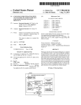
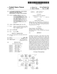
In order to meet these demands, a new data acquisition system had to be
designed. The system was named DAISY, an acronym for Data Acquisition
SYstem. Emphasis was put on modularity, both in the software and in the
hardware. The VMEbussystem waschosen as the building stone for the front-end
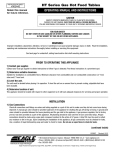
system. The host computer, a ND5800 from Norsk Data, was already present. An
overview of the system is presented in figure 1.1.
CAMAC B^
ND5800
VME
NIM
# V MC68020 J
Domino
MC68020,
ND 120
•H
Figure 1.1 Overview of the data acquisition system
3
2. VME front-end system
The front-end part of the acquisition systems is responsible for the read-out of
digitaLzation devices, pattern word generation and the creation of event buffers.
First, an introduction to the operation of the front-end data acquisition system is
given. The following chapters describe the hardware components and the soft
ware of this system.
2.1 Getting started ..
The front-end system is operated from the Apple Macintosh. First of all, ensure
that the VALET crate is powered on and that theconnection between the FIC 8230
CPU board and the Macintosh is present. On the VMEbus side, cable 9051 should
be plugged into the serial port marked TERMINAL. This cable should then be
connected to the modem port of the Macintosh.
Now it is time to launch the Bridge application. The program is found in the
folder DAISY. To start it, double-click the Bridge4.0 icon.
After a few seconds, the VALET-Plus login dialogue window will appear. The
settings shown are the appropriate ones. Generally, there should be no need to
change Li;^m. Click on the OK button (or give RETURN) to continue.
Welcome to the URLET-Plus Bridge U4.D
Connection to URLET uia :
® Mac Modem Port
O Mac Printer Port
Transmission baud rate :
® 19200
O9600
O4800
G Trace Selection
Communication on :
0 7 bits
<*> 8 bits
RTS/CTS [I'otocol:
O Enabled
® Disabled
G3 Issue Login Request
(
OK 1^
What then happens will depend on the state of the VALET. There are three
scenarious: Cold start, i.e. a VMEbus reset has been performed, warm start and
finally warm start with a running application.
First consider a cold start. The dialogue will then look like:
MC 63020 + MC 68881: rloniCa - version I . I
from 8 9 / 4 / 7 . Cold s t a r t . Begin:
>PILS
Welcome t o t h e DA I SV f r o n t - e n d system
The f o 11 oui i ng programs a r e ava i I ab I e :
USE E v e n t . e n d
: Data R e q u i s i t i o n
USE Capipari.cmd : CflMflC RDC/TDC S e t - U p
USE T e s t . a n d
: Test S u i t e
Command? c I ear ed i t s t y I e
L e a v i n g immediate mode
Command?
•
f o r p r o p e r o p e r a t i o n w i t h t h e Mac
Note that command prompt in MoniCa debugger is > and in PILS command
mode Command?.
The message shown above (Welcome to ...) is printed by a script named
STARTUP.PIL which is automatically run at PUS start-up.
After a warm start you will enter PILS command mode immediately, when an
application is running the screen will be blank. Issue CTRL C to return to PILS
command mode. It may be usefull to run the STARTUP.PIL script manually to set
up the correct path, select USE from the PILSfile menu.
According to the documentation, VALET-Plus is not multifinder compatible.
However, itispossibletorunundermultmnder if VVVLETW'/us is quit beforeanother
Macintosh application is started. The quickest way to quit the BRIDGE is to click
on the close icon.
,
_ . .
«
Bridge
5
ST
2.1.1 Preparing for a run
Before the acquisition is started, it is highly recomended to perform some basic
test functions and run through the set-up for CAMAC devices.
Two applications are available for this purpose; CAMPARI for CAMAC devices
set-up and TEST. The corresponding compilation and loading scripts are named
CAMPARI.CMD and TEST.CMD. They are located in the folder CMD. Select the
USE command from the PILSfile menu to activate them.
TEST
Issue the command
USE Test.cmd
or use the menus as described previously. The following menu will appear:
I
I
Oslo Cyclotron Laboratory
Test Programs
Choose A
B
C
D
E
I
I
Test TPU System
Test SILENfi 4418/U HDC"
Test SILENfl 4418/T TOS"
Test CflMflC datauray
Initialize CHCRC Crate
EXIT from testprogram
TEST>
A: The TPU test option launches a sub-menu. The results of the test are observed
by inspecting the front-panel LEDs.
B: Test the CAMAC ADCs. Two functions are provided, an internal test function
and a test using external input signals. The internal test is intended to show
whether all channels are working. The external test requires some input signals
from the detectors. Data are read without using the hit pattern, consequently
most channels will bee zero. This option may be used to see if all channels receive
data. Another useful application is to check the offsets. Zero energy, i.e. no signal,
should give zero as a result. Frequently, one will read numbers like 4094,6 and
so on. This implies that the offset should be adjusted. This is done by the program
CAMPARI.
C: The same test for the CAMAC TDCs.
6
D: Test the CAMAC Branch Highway bus. The Branch Highway connectors are,
unfortunately, rather fragile. It is therefore highly recommended to check it
before starting the acquisition. The test function writes bit patterns to a register
in the Borer Display Unit, located in slot 1, and reads them back. Any bit errors will
be reported. The test runs 10000 cycles before terminating.
E: Reset the CAMAC. This option issues a Z<ycle on CAMAC dataway.
CAMPARI
Thepurpose of this application is to set the parameters for the SILENA 4418/V and
SILENA 4418/TCAMAC ADCs and TDCs [1,2]. These devices havea parameter
memory which holds information on:
• Upper Level Discriminator (ULD)
• Lower Level Discriminator (LLD)
• Offset
• Common Threshold
The latter is applicable for ADCs only. The parameters loaded will survive a
CAMAC reset (Z-cycle), but will be zeroed after a power off.
The program is named CAMPARI, an acronym for CAMac PARameter Input. To
launch the program, issue the command
USE Campari.cmd
The following menu will appear:
Reading set-up data from f i l e
I
I
' SETUP.DAT'
Oslo Cyclotron
Experiment setup
Choose fi
B
C
D
Set CRMRC ADC parameters
Set CRMRC TOC parameters
SRUE setup to f i l e
I n i t i a l i s e CfUlfiC Crate
EXIT from setup
CAMPAR I>l
Selecting A pops up the sub-menu for ADC set-up:
7
I
I
I
CAM AC ADC Parameter Input
Choose fl
B
C
D
I
o e i luririun inresnoia
Set Upper Level Discriminators
Set Lower Level Discriminators
Set OFFSET values
EXIT
*
CflMPRRI>
The use should be self-explanatory. There is a choice between individual, i.e.
channel by channel set-up, or common set-up. To see the current values, select
individual mode. Typing "CR" in reply leaves the current value unchanged,
typing a "*" moves you one level up in the hierarchy.
After the values are successfully entered they may be saved to a file, SETUP. DAT,
found in the folder DAISY. The contents of this file will automatically be loaded
into parameter memory when the CAMPARI application is started.
As the parameter memory is cleared after a power off of the CAMAC crate, the
program should always be run to load the contents of SETUP.DAT. So far, the
ADCs and TDCs have proven to be verv stable as far as the offset is concerned.
The values currently saved to SETUP.DAT should probably be correct. Tabel 2.1
presents the current values from SETUP.DAT. The numbers in paranthesis are
the actual register contents.
It would, of course be more convenient to combine all test and set-up function into
one single application program. The small amount of memory (2 MBytes)
available on the FIC 8230 makes this impossible.
ADC1
ADC2
ADC3
ADC4
TDC1
20(4)
20(4)
20(4)
20(4)
-
ULD*i[mV]
0(255)
0(255)
0(255)
0(255)
0(255)
0(255)
0(255)
0(255)
LLD*[mV]
0(0)
0(0)
0(0)
0(0)
0(0)
0(0)
0(0)
0(0)
Offset "[ch]
4(132)
6(134)
4(132)
6(134)
0(128)
0(128)
0(128)
0(128)
f
Common '[mVJ
"
TDC2
100% of full scale
*
0% of full scale
41
128 - 0 channels
Table 2.1 The current settings of the parameter memory
8
TDC4
-
0 = 0.0 V. 255= 1.2 V
"
TDC3
2.1.2 Starting the data acquisition
The front-end system part of the data acquisition is started by typing the
command:
USE Eventcmcl
in PILS command mode. The following menu appears on the screen:
I
I
Oslo Cyclotron
Data Acquisition System
fl
B
C
D
*
:
:
:
:
:
Ctr^-C :
I
I
START data a c q u i s i t i o n
DUMP of data b u f f e r <buffer one)
P r i n t STATUS
E n a b l e / D i s a b l e TPUs
EXIT
STOP d a t a a c q u i s i t i o n
DfllSV>
After initialization, all three TPU modules will be enabled. If one or more
modules are not to be used, i.e. they will not have any cable connected to the ECL
input connector, they must be disabled. An unconnected module will make the
system hang.
Starting the acquisition is simply done by typing "A". The time and date of the
start-up is printed out.
Stopping the data acquisition is done by CTRL C. The program is restarted by
typing RUN.
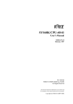
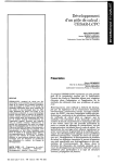
2.1.3 Resetting the VME system
If problem should occur during loading of the VALET-Plus system or if the
system otherwise should get stuck, a reset cycle must be issued. Press the upper
of the two buttons on the FIC 8230 front-panel extended console. The button is
indicated by an arrow on figure 2.1.
9
Figure 2.1 The VME front-end system. On top, the ADC interface crate is visible.
10
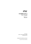
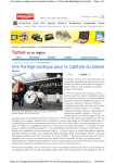
2.2 Hardware
A block diagram of the components comprising the front-end part of the acqui
sition system is shown if Figure 2.2.
urn
ADC
«NT
rn
VALET
PILS
ADC
NW
ADC
ADC
ADC
ADC
NT.
INT.
NT.
ITT^
CAMAC DATAWAV
•2MB
RAM
AOC
TPU
TPU
MAST.
SIAVE
16
BIT
PATT.
16
BIT
PATT.
ITTTTTT1
Figure 2.2 Block diagram of the VMEbus front-end system
2.2.1 Processor unit
The processor module used is the FIC 8230, Fast Intelligent Controller, from CES
[3]. It is based on the MC68020 ".-processor running at 16.67 MHz. The FIC 8230
has a dual bus architecture which permits simultaneous local computation and
direct access transfer from VMEbus to the global on-board memory. The unit is
equipped with a 2 MByte DRAM plug-on module and the MC68881 floating
point co-processor. The FIC 8230 has master and slave VMEbus ports and a
master-only VSB port.
Our CPU board has been configured to run the VALET-Plus system [4] developed
at CERN. The VALET-Plus firmware is delivered on 16 EPROMS. Two 128k x 8
11
bit EPROMS holding the MoniOt code is mounted on the CPU board using a
piggy-back module [5].
The 14 remaining EPROMS are mounted on a separate EPROM socket card, the
TSVME20416],
The FIC 8230 is connected to the Macintosh SE through a RS232 link.
2.2.2 Trigger pattern unit
The Trigger Pattern Unit (TPU) constitutes an interface to the trigger logic of the
experimental set-up [7]. The TPU module supplies information on which detec
tors actually giving signals. The list of active parameters is called the pattern
word. The pattern word is used by the read-out program to set up an event
structure and to read out the digitalization devices.
A full description of the module is found in [8]. The documentation available at
the cyclotron laboratory contains the latest updates and fixes. The TPUs were
originally designed with interrupt capabilities. This has, however, neither been
needed nor implemented.
STATUS REGISTER:
15
cw
14
13
12
ADC code
7
0
TPU baseaddress
Selector i
cw: control word
ADC code
TPU base address:
TPU1
TPU2
TPU3
14
8
no. of active channels
Jism i
15
$FFFFxO, 16bit.read/write
13
12
Current settina:
strap 29
strap27,2B
=1 <=> "OFF"
=1,0<=>"OFF"
U43
=0A <=> sw4,2
•OFF"
=0B <=> SW4.2.1 •OFF"
=0C <=> SW4.3
"OFF"
others "ON"
8
Write
7
6
LeCnMMBwMMI
tst LeCr: Enable Test« /Lecroy discr mir ators
Etst: Test the event line
opt Optional l ED
opt OptionaJ I ED
IntE n: Interruf >1 enable
Figure 2.3 The TPU master status register
12
3
2
1
0
Elat
opl
opt
ht
En
Note that the TPU modules must be placed in special slots, i.e. slot 7,8 and 9, as
the ECL supply and termination voltages are supported here only. Currently, one
master and two slave modules are installed in the VME crate. One extra module,
configured as master, is available. There are no extra printed circuit boards.
Figure 2.3 shows the TPUstatus register in read and write mode respectively. The
current settings are indicated.
2.2.3 NIM interface system
An interface from VME to NIM ADC's is provided using the NBI design. A
comprehensive description of this system is found in [91.
The system consists of three parts:
The NIM Controller is implemented on a double height VME card. The interface
to the VMEbus is found on this module. The VME base address is defined by
switches BA8-BA31. Currently the address is set to EFFF80 . This is done by
setting BA20, i.e. switch 5 on component U43, to "ON" while all other switchesare
"OFF. We utilize only the standard VME address, a 24 bits address. Note that the
address lines 24-31 are not correctly connected on the PCB board. This must be
corrected if a full 32-bits address is applied.
16
The PCB layout was performed on our CAD/CAE system using the Visula
software irom RACAL/REDAC. The cards were manufactured by EB-Elplex.
One NIM Controller module is installed in the VME crate and one spare module
is available. In addition, there are several printed circuit boards available.
The NIM Controller is connected to the ADC Controller through a flat-ribbon cable.
The ADC Controller mainly contains timing logic which is not usxl in our ap
plication. The ADC Controller is located in a separate single-height Euro crate.
PCB layout of the ADC Controller was performed on the institute's CAD/CAE
system using the Visula software from RACAL/REDAC. The cards were
manufactured by EB-EIp)ex. One module is in operation, another is available.
Several PCB cards exist.
The ADC Interface modules are located in this crate, one module for each NTM
ADC. There are 16 modules available, additional PCB cards may be obtained
from NBI.
The single-height crate has a power supply of its own, a VERO PK 25 mono volt
delivering 5A on 5V. The crate backplane is a home-brew, a flat-ribbon cable with
64 pins A-C row euro-connectors fitted.
13
2.2.4 CAMAC interface
Interface to CAMAC devices is accomplished through the CBD 8210 CAMAC
branch driver from CES [10]. It is connected to the CCA2 2110 crate controller
through Branch Highway.
The branch number isset to "1" on the CBD 8210. The Branch Highway cable suffers
from rather fragile connectors. The cable should not be touched unless absolutely
necessary. An extra Branch Highway cable (2 m) is available.
2.2.5 Power supply and crate
The VME crate is delivered by FORCE Computers [ 11 ]. It is equipped with full 21
slots PI and P2 backplanes supporting 32-bit data and address. Each signal line
is terminated with two 33OCI/470Q resistor networks.
The VME system is powered by a FORCE SYS68K/PWR-2Q primary switched
power supply [12]. It supplies the following output voltages:
+ 5V / 90A
+12V / 20A
-12V / 5 A
A DC-DC voltageconverter fitted on the rearprovides for the voltages-5.2V and
-2.0V needed for ECL circuitry. See [8].
14
2.3 Software
The software of the front-end system is developed using the VALET-Plus system
[13]. Valet-Plus is a modular VMEbus based microcomputer system developed at
CERN for use in applications like testing of electronics, equipment control and
data acquisition. The VALET-Plus architecture isolates instrumentation specific
hardware and software in a VMEbus crate which iscalled the VALET. The VALET
is driven by a MC68020 processor which runs application programs under a
resident monitor, MoniCa, using ROM based PILS (Portable Interactive Language
System) and standard libraries. It can access instrumentation buses like CAMAC,
FASTBUS, VMEbus and GPIB. Support for standard peripherals as well as the
interface to control the VALET are provided by a personal computer, in our case
a Macintosh. This personal computer is called the I/O server, running a utility
called the Bridge. The link between the VALET and the I/O server is made via a
RS232 (V24) serial link. Both systems request services from each other across this
link using a RPC (Remote Procedure Call) technique.
2.3.1 Event_Builder
The Event_Builder task is coded in PILS [14]. The actual coding is done on the
Apple Macintosh using the program editor QUED/M. When designing the pro
gram attention was put on speed. Coding elegance was sacrificed for the sake of
maximum throughput. Asa result, the main read-out loop contains no procedure
calls. Test has shown that calls to subroutines give rise to a considerable overhead
in PILS. Figure 2.4 shows a simplified float diagram of the task.
A double buffering technique is applied in order to achieve high throughput. The
two data buffers are 32kW long, a word length of 32 bits is used.
The event loop starts with thedetection of an event, a master gate provided by the
TPU master module. Before any read-out is performed, a pile-up* flag is checked.
If a pile-up condition is found, the event is discarded and all digitalization devices
reset.
The hit pattern words are fetched from the TPUs. Each pattern word is divided
into four hit pattern nibbles, again to gain speed in checking which ADCs/TDCs
to read out. (A nibble is a four bit entity).
Read-out of CAMAC devices is done using calls to the standard CA\.AC library
[15].
Finally, the ADCs and TDCs are reset and the Event_Builder is ready for next
event.
1
The pile-up flag is Mt by the input signal from the Quad Pile-Up Reject NIM module. A pile-up
condition occurs when two pulses overlap, thus producing a spurious energy signal.
15
Chang» bullar
HMMADCVTDC*
fltwl bullar poplar
•
•f
Endloop
RtpMttorTPU2,TPU3,...
J
Figure 2.4 Float diagram of the Event Builder
Measurements of the processing speed has been undertaken. The measurements
are carried out monitoring the INHIBIT signal from the master TPU on an oscil
loscope. By inserting jumps to the reset statement on various spots in the code,
the time elapsed for each operation can be found. The read-out time for an event
with two parameters only is about 215 lis, a three parameter event will take
approximately 240 us. Based on these numbers the maximum read-out speed,
using a typical event length, is about 180 kBytes/s .
16
On basis of these measurements we also observe that at least 70 us will elapse before
any read-out of ADCs/TDCs can lake place. After this period all ADCs/TDCs
will have finished their conversion. Consequently, it is not necessary to test this
condition.
2.3.2 Memory allocation
Data buffers:
The data buffers are freely allocated in PILS workspace. The actual start address,
defined at compilation time, is found using the PILS statement address. Absolute
VMEbus addressing is not utilized as calls to the VMEbus library introduce
considerable overhead.
However, one factor must be observed. As the VMV link operates through a 1
MByte window, the buffers must be contained within a 1 MByte boundary in
memory. The Event_Builder features a command :
C:
Trint STATUS
to examine the start and end addresses of the data buffers.
FIC8230 on-board DRAM
BUFFER 1 address space
BUFFER 2 address space
20002000
2010H660
2012A660
- 201FFFFF
- 2012R65C
- 2014A65C
Figure 2.5 The current data buffer addresses
Figure 2.5 shows the current start and end addresses for the two buffers. Any
change in the Event_Buildercodemay cause thebuffers tobemoved in workspace.
MC 68020 + MC 6888I: MoniCa - Begin:
> SVSC0NF
*** SYSTEM CONFIGURATION ***
Total RAM space : 2040 kbytes
First RAM address : 20002000
Last RFttl address : 20IFFFFF
Percentage of RRM for PILS workspace : 55
Additional Histogram space :
0 kbytes
Number of extra fiPC messages a l l o c a t e d :
1
CRMRC Branch d r i v e r without DMA for branch »
1
Figure 2.6 The VALET-Plus system configuration
17
If the buffers should fall outside such a 1 MByte boundary, this can be adjusted
by changing the percentage of RAM used for PILS workspace. This is examined
using the MoniCa command SYSCONF. Figure 2.6 displays the current configu
ration.
Message_Box:
Unlike the data buffers, the Message_Box is locked in memory at a given location
in VMEbus address space. The start address of the Message_Box is set to
201F7FD0,,. The first location of the Message_Box contains the data buffer start
address. The layout of the Message_Box is described in section 5.
2.3.3 Data format
The data format is fully under program control. It may thus easily be changed to
fit future application. A sketch of the data format is presented in figure 2.7. Note
that only the lower 16 bits are actually used in the processing despite the fact that
the Event_Builder operates with 32 bits wordlength.
DATA FORMAT
i
s
u
1
E V M I I toneth
TPUWant.
•
B
PATTERN WORD
E
V
E
N
T
DATA
DATA
1
TPU ManL
E
V
E
N
PATTERN WORD
DATA
DATA
DATA
DATA
•
I
1 f
Evwrtlinpfi
Figure 2.7 The data format
18
T
The first word of the event gives the event length. The example shown in figure
2.6 has a length of 11 words. The bits 12 - 1 5 are set to "1" as a tag for the event
header. Note that the identification tag itself does not provide a unique identifi
cation, pattern words may (though unlikely) have these bits set. However, since
the event length is known, problems are avoided.
Following the event header is a TPU identification word. Each TPU has a
associated code, TPU 1 has the code SOOA,^ TPU 2 is 800B and TPU 3 is 800C .
]6
16
The next word is a pattern word, each bit identifying a given detector. The scheme
is that each bit set will give rise to two datawords. That is, read-out of two
digitalization devices will take place.
2.3.4 Pattern bit allocation
As mentioned in the previous section, each bit of the pattern words are associated
with two ADC/TDC channels. Figure 2.8 shows how the patterns from the three
TPUs are allocated. Note that the channel number equals bit number + 1.
TPU1 has been allocated to NIM devices. Only the odd numbered channels are
used for data read-out. Channel 1 and 3 are used for the particle telescopes. The
8 telescopes are multiplexed into two groups, a and b. The first data word contains
the AE energy, the second the energy deposited in the end-counter, E. Channels
5,7,9,11,13 and 15may be used for other NIM interfaced detectors as for example
Ge counters. Here, the first data word gives the energy while the next contains
time information.
The even numbered channels may be used as logical bits. The actual meaning of
such a bit must bedefined in the sorting routine. They are typically used to denote
a singles or a coincidence event.
TPU 2 and TPU3 are allocated to CAM AC ADCsand TDCs. Again, each pattern
bit corresponds to two data words. The first is an energy, that is an ADC is read
out. The second is the time, hence a TDC is read out.
This allocation scheme may be changed to suit the experimental conditions. The
only part which will be affected is the sorting routine.
19
TPU1
1
2
3
4
5
•
7
«
9
S- A0C1
* » ADCS
,
AE,
E,
^ ADC3
* ^ ADC4
lEk
n.u.
^ - A0C5
V . ADCS
n.u.
11
« ^ ADC11
^ ADC12
12
n.u.
13
S- ADC13
^ A0C14
14
n.u.
15
^ ADC15
V . ADC1S
n.u.
ADC3.0 E
TDC3J) T
2
^
^
3
^
ADC1.2 E
V . TDC1.J T
V
ADC3.1 E
10(3,1 T
ADC3.2 E
TDC&2 T
. , ADC1.J E
V . TDC1.S T
^
A0C3.3 E
V . TDC3.S T
^ ADC1.4 E
V . TOC1.4 T
T
s* ADC3.4 E
V TDC3.4 T
- ADC3.S E
< , TDC3.S T
*. ADC1,( E
V . TDC1,« T
*• ADC3,« E
* » TDC3.6 T
,
*
A D C ,
,
'
TDC1,I
E
E
T
.
'
•
"
^
<
E
T
g
^ ADC2.0 E
•^» TDC3.0 T
n.u.
^ - ADC»
* ~ ADC10
^
V
^
ADC1.1 E
V . TDC1.1 T
>• <^
II.U.
- - ADC7
V . ADCS
i
2
4
E
T
TPU3
^ ADC1.0 E
V . TDC1.0 T
1
IUL
10
"
TPU2
1 0
„
E
T
1 2
E
T
,,
1 3
..
E
T
l
s
ADC1.7 E
T0C1.7 T
^ - ADC3.7 E
V TDC3.7 T
^
<-
ADC2.1 E
TDC2.1 T
10
^
ADC2.2 E
11
s*
V
ADC4.0 E
TDC4.0 T
s*-~
^
*-•
ADC4.1 E
TDC4,1 T
ADC4.2 E
TDC4,2 T
^ ADC2.3 E
V . TDC2.3 T
12
^
A0C4.3 E
*•» TDC4.3 T
^
<
ADC2.4 E
TDC2.4 T
13
^ - AOC4.4 E
* - TDC4.4 T
^
ADC2.5 E
< - TDC2.5 T
14
. - ADC4.5 E
* - . TDC4.5 T
s- ADC2,« E
V . T0C2,« T
15
V . TOC2.7 T
"
^
ADC4.0 E
*-> TDC4,0 T
^- ADC4.7 E
V . TDC4.7 T
Figure 2.8 Pattern map
A full listing of the Event_Builder task source code is found in Appendix A.
20
2.3.5 Compilation and loading
STARTUP.PIL:
CLEAR PAGE
SET INDENT 3
SET PATH d i s k : D A I S Y : c m d :
PRINT ""
PRINT
PRINT
PRINT
PRINT
PRINT
PRINT
PRINT
PRINT
PRINT
PRINT
PRINT
PRINT
P.1INT
PRINT
PRINT
nn
""
""
""
..
»
"
"
"
"
....
."
I
I
Welcome to the DAISY front-end syatem
I"
I"
I
I
I
I
I
I
The following programs are available :
I"
I"
I"
I"
I"
I"
."
USE Event.cmd
: Data Acquisition
USE Campari.cmd : CAMAC ADC/TDC Set-Up
USE Test.cmd
: Test Suite
PRINT
EVENT.CMD:
CLEAR ALL
CLEAR PAGE
PRINT " l o a d i n g e v e n t _ b u i l d e r :"
FETCH M A C _ P H I 2 % d i s k : D A I S Y : P r o g r a m s : E v e n t _ b u i l d e r
COM
RUN
21
3. VME to ND link
The transfer of data and handshake signals between the VMEbus front-end
system and the ND-5800 computer is realised using a VME to VME link. A
description of hardware and software is presented.
3.1 Operating the link
The software running in the link between the front-end and the MD-5800
computer requires no user interaction. Hence, this task should be invisible to the
user. It is none the less, necessary to check that the system is running.
The status of the task is easily checked by inspecting the LEDs BR3 and AS on the
CES VMDIS 8003 VMEbus monitoring unit. The LEDs will flash with an interval
of approximately 3 seconds when the DOMINO controller is running. If no ac
tivity is found, the controller must be restarted.
3.1.1 Restarting the DOMINO controller
The DOMINO controller is restarted from the ND-5800 computer. It is necessary
to be logged in as user SYSTEM in order to get access to the DOMINO MONITOR.
Ask the system administrator if the password is unknown. The procedure will be
as follows:
@nd (domino)domi-monitor
DM: open-path server 50
Connected to MC68020 based DOMINO
DM: soft
DM: place (kjf-daisy)ces
Placing (PACK-TWO:KJF-DAISY)CES:DSEG
Placing (PACK-TWO:KJF-DAISY)CES:PSEG
DM: run
Type T - M ' <CR> <CR>
t-m
<CR>
<CH>
- Data Buffer Eater Transfer of data buffers from VME
system to ND-5800 computer
22
@
DM: target-status
Controller status
Cache
Memory protection
: running
: on
: on
DM: exit
Unfortunately, it is not possible to run this procedure as a mode file. This is due
to a synchronization problem between the DOMINO controller and SINTRAN.
23
3.2 Hardware
3.2.1 The DOMINO
controller
An interface between ND-5000 computers and VMEbus has been developed by
Norsk Data [16]. A prototype has been installed on the laboratory's computer. It
is implemented asa MFbus card, located in a master slot in the MFbus crate inside
the ND-5800 computer.
The interface module is designed accord ingto the DOM/NO concept [17,18], which
is a standardization of I/O controllers for the 5000-series. The controller inter
faces the MFbus, the main bus of the ND computers, and a serial communications
bus, Octobus on the ND side. The VME device looks like a DOMINO to the MF
system, and the MF system looks like a VME master to the VME system. The
controller is designed as a VME master-only, using the SCB68172 bus controller
chip.
3.2.2 Internal VMEbus crate
The DOMINO controller may either be used mounting one VME card on the top
of the motherboard or by mounting a separate 3-slot VME backplane to the rear
of the MFbus crate. In our case, we needed 2 slots to accommodate the VBR8212/
VBE8213 modules. Unfortunately, our computer is not equipped with the proper
cabinet, the MAXON cabinet, and there is not sufficient space on the rear of the
crate. The problem was solved connecting the VME backplane to the MFbus
backplane with a flat-ribbon cable. It is obvious that this violates the VMEbus
specifications. However, we have experienced no problems so far. An ancillary
5V power supply for the VME modules is located inside the 3-slot VME crate.
Note that one of the VME slots is defect at our installation.
3.2.3 VME-VME link
The VME-VME connection is realised using the VMVbus concept of CES [19]
which extends the VMEbus to a multiple crate environment. The transfer band
width of this system is in excess of 8 MBytes/s (branch < 10 meters). Transfer on
the bus is mapped through a 1 MByte window.
24
The VMVbus is a multiplexed bus for the full 32 bits address and data of the
VMEbus. The electrical signals are transmitted differentially on two "twist-andflat" cables. Each signal line is terminated in both ends by an active terminator,
the plug-on module VBT 8214.
Up to 15 crates may be connected, each crate is identified by a hexadecimal
number (1 - F). In our set-up the internal VME crate in ND computer is number
"1" and the front-end acquisition crate is number "A".
3.2.4 Architecture
Figure 3.1 shows the architecture of the VME to Nord link. All transfers between
the two system:? are initiated from the Nord crate holding both the VBR 8212 and
the VBE 8213 units. The FIC 8230 processor module of the front-end crate acts as
a VME slave during transfers.
L
VBR
' i
VMV
REC
OVER
1
1
(
•
'•;,-'
• " ; - '
<
' - , ; -
'•-<
VMEb»
VBE
VBR
VMV
VMV
REC
EIVER
TRANS
MTTER
1
>
ND-5800
[1 J|
••
<
INTERNAL VMEDu. paloU)
>
1
VMEtoWlM*
2 0
• W»"
OCTOBUS 1
IMWTac* |
<
<
| DRAH
MFbia
Adipttr
1
MFtHM
1
OCTOflUS
DOMINO
CONTROLLER
1
Figure 3.1 Block diagram of the VME to Nord link
25
>
>J
3.3 Software
The software of the DOMINO Controller runs as a stand-alone task. The software
is developed in the programming language PLANC [20], a member of the
ALGOL/PASCAL family of block structured languages. PLANC is mainly
inteded for writing system software such as operative systems and compilers.
PLANC allows for in-line assembler code. This is important in the current
application as access to absolute physical memory addresses is performed.
It is vital to make the buffer transfers as fast as possible. The VME front-end
Nord wmmaphon loop
Figure 3.2 Float diagram of the Move_Buffers task
26
system is locked during data-buffer transfer. The actual transfer time has been
measured to 65 ms for a buffer of 32 k 32-bit words. This gives a transfer rate of
about2MBytes/s ingoodagreementwiththevaluecalculatedusingthenumbre
of processor cycles and clock frequency (16.67 MHz)
/
The choice of programming language for the DOMINO Controller was an easy
one, PLANC is the only cross-compiler excisting. The source code is compiled on
theND-5800 MC68020 PLANC compiler, linked with the corresponding libraries
and then downloaded to the DOMINO Controller.
Figure 3.2 shows a flow diagram for the main loop of the task running in the
DOMINO Controller, named Move_Buffers. The Move_Buffers task acts like an
intelligent DMA controller.
3.3.1 Memory mapping
The DOMINO controller has direct access to the physical memory of both the
VMEbus and to the ND Mpm5 multiport memory.
Addresses with bit 31 set to "1" are taken as MFbus addresses. Note that a task
running on the ND-120 processor must use an address offset when accessing the
Mpm5 memory due to the local ND-120 memory. The offset is 1200 0000 .
g
ND-120
MpmS
DOMINO controller
21660000B
766 0O00B
200 1754 0OOOB
476000H
1F6000H
B03E CO0OH
2176 0000B
7760000B
200 1774 0000B
47E000H
1FE0O0H
S03F C000H
Figure 3.3 The address mapping in the DOMINO controller
(B denotes octal, H hexadecimal)
Figure 3.3 displays the addresses of the data buffer and the Message_Box viewed
from theDOM/NOcontroller.Thedatabufferstartaddressis21660000 seenfrom
a ND-120 task, which gives the physical Mpm5 address 766 0000, (1F6000J. The
DOMINO controller address is then given as:
e
27
1F6000 • 2 -> Set bit 31 ->• 803E C0000
16
l6
The multiplication by 2 is due to that MC68k processors use a byte as the basic
addressable unit while ND uses a word (16 bits).
The DOMINO controller can access only 24 bit (16 MByte) on the VMEbus
directly. When a standard address is used, theaddress map for VME will be from
100 0000,, to IFF FFFF„. Bit 24 is set to "1" to route to the VMEbus address space.
The VMV system performs a mapping through a 1 MByte window. As an
example consider the first location of the message box which is located at 201F
FFD0 . In slave mode the address is 1F FFD0 . The VMV link maps the address
issued from the DOMINO controller as follows (c.f. [19]):
1S
I6
EF FFDO, : DOMINO address
OF FFFF : VMV mask
10
: VMV sets MSB
6
l6
I6
Which gives 1F FFD0 , the address in slave mode.
16
A full listing of the Move_Buffers task source code is found in Appendix B.
3.3.2 Compilation and loading
Compilation and linking of the Move_Buffers task is done running this mode-file
on the ND-5800 computer:
@g
0@
@S
88
Mode file to compile and load the Move_Buffers task
File: (kjf-daisy)move-buffers:mode
se
3del-fi (kjf-daisy)ces:nrf
8nd (plane)pl-mc6B-i
com (kjf-daisy)move-buffers,,"(kjf-dai3y)ces"
8LINK-LOAD
REL-DOM ces
DEL-DOM ces
SET-DOM "ces"
SET-SEGMENT-NUMBER OB,,,
OPEN-SEG "ces",,,
LOW-ADDRESS 600000B D
28
LOW-ADDRESS 400000B P
LOAD ces:NRF
LOAD (PLANC)PL-68020-I00
LI-E-D
LI-E-U
EX
Downloading of the code to the DOMINO controller can unfortunately not be
done through a mode file. The reason for this is that there Is no synchror ization
mechanism between the DOMINO controller and SINTRAN. The following
commands must be given:
nd (domino) domi-monitor
open-path s e r v e r 50
30ft
place (kjf-daisy)ces
run
t-m
[CR]
[CR]
8
Please note that the domino-monitor is accessible for user SYSTEM only.
29
4. Sorting and data storage
On-line sorting and data storage is done on the ND-5800 mini-computer. This
computer has two CPUs, a 32 bit ND-5000 CPU and a 16 bit ND-120 CPU. The
latter is responsible for I/O operations. This part of the acquisition system
consists of several real-time tasks, some run on the ND-5000 part, some on the
ND-120.
The storage devices available is Exabyte EXB-8500 and STC magnetic tape. The
storage capacity of the Exabyte is 5 CByte in 8500 mode and 2.5 GByte in 8200
mode. The capacity of the magnetic tape is about 180 MByte.
4.1 Controlling the data acquisition
Theoperatorcontrolofthedata acquisition takes place on theSHIVA [21] console
terminal (Terminal 44). The acquisition system has been interfaced to the SHIVA
command input task. A sub-menu (choice L in the top-level menu) implements
the commands. The commands are:
DAISY-LOAD-UNLOAD
DAISY-START
DAISY-PAUSE
DAISY-STOP
DAISY-STATUS
DAISY-DUMP
DAISY-CLEAR
DAISY-SNAPSHOT
4.1.1 The commands
• DAISY-LOAD-UNLOAD
This command must be issued prior to any other "DAISY" command. The com
mand is particularly useful when a new sorting application routine is to be
loaded.
• DAISY-START
Starts up the data acquisition. The acquisition may run with "NONE",
"MAGTAPE" or "EXABYTE" storage medium.
• DAISY-PAUSE
Temporarily stops the data acquisition. No filemark is written. The acquisition
may be restarted with DAISY-START.
30
• DAISY-STOP
Stops the data acquisition. A filemark will be written to the output medium. The
user will be asked if the medium should be unloaded.
• DAISY-STATUS
Prints out a page of status information. An example is shown below.
*
*
*
*
*
*
*
*
*
1991-02-26,09:53:54
Acquisition last started
SHIVA acquisition is
VME acquisition is
Storage Medium
EXABYTE Position
Records accumulated
Number of bad records
Fraction of records sorted
Average datarate
RUNNING
RUNNING
EXABYTE
8324
238
0
100%
81 evenls/s
The EXABYTE Position is the absolute record number (counted from beginning
of tape) on the Exabyte cartridge. Filemarks are not counted.
The fraction of events sorted depends on the event rate. During low-rate particlegamma runs, all data will be sorted. In singles runs it will typically drop to 50 %.
• DAISY-DUMP
Dumps the sorted spectra (histograms) in memory to disk file on the user area
KJF-SWAP. Two dump modes are available. A "singles" dump will write the 1D spectra S1-S32 only. The "multiparameter" dump will write all 1- and 2-D
spectra except S1-S32. A list of the spectra is given in Table 4.1.
• DAISY-CLEAR
Clears the spectra in memory. The spectra on disk files will not be affected.
• DAISY-SNAPSHOT
Prints out some few events from the current databuffer. The data is shown in
hexadecimal representation. C.f. chapter 2.3.3 for interpretation.
In order to make the spectra accessible for the SHIVA system, they must first be
dumped to disk files using the DAISY-DUMP command. This will take 4 0 - 6 0
seconds. A message notifies the user when the dumping is finished. Thedata may
then be imported to SHIVA using the READ-SPECTRUM command for 1-dimensional spectra and 2DIM-READ for the2-dimensional ones. First of all,define
the default directory and user by giving the command:
31
SET-DEFAULT-DIRECTORY (PACK-ELEVEN:KJF-SWAPj
As an example, consider the 2-dimensional spectrum THICKSP. Fust, we must
define a 2-dimensional spectrum in SHIVA:
SET-2D-SPECTRUM 2048 8
We have now defined the spectrum SP2DIM. Next, issue the command
2D-READ *THICKSP SP2DIM
to move the spectrum into SHIVA workspace.
Name
X-Dim
\-Dim
Comment
ESP
2048
8
E Counter
DESP
2048
8
AE counter
EDESP
THICKSP
2048
2048
8
Particle telescopes
8
Particle identification
GESP
4096
6
Ge counters
TGESP
NASP
512
2048
Ge time spectra
Nal counters
TNASP
512
6
32
32
PSP
2048
P1SP
2048
-
Particles in coincidence
Nal time spectra
Particle spectrum
GE1SP
4096
NA1SP
2048
TGE1SP
512
TNA1SP
512
S1
4096
S8
4096
S9
2048
-
S32
2048
-
Ges in coincidence with as
Nals in coincidence with as
Summed TAC with gate on as
Summed TAC with gate on as
General purpose singles spectra
Table 4.1 The on-line sorting spectra
32
4.2 Program architecture
In this section, the tasks comprising the NID part of the data acquisition system is
described. Both the ND-120 CPU and the ND-5000 CPU are utilized. The ND-I20
CPU takes care of the I/O intensive tasks while the ND-5000 CPU is used for
heavy calculations, i.e. the on-line sorting. All programs are coded in ND Fortran
77 [22].
Figure 4.1 displays the overall architecture of the various real-time programs. A
local control program, DACQC, takes care of the interface to SHIVA. The com
munication between the SHIVA command handler task and DACQC is imple
mented using the internal device mechanism in SINTRAN.
U M T Command Input
Local Contra! program
ioJ
MTDtIP/
EXDHP/
MDUUM
OSORT
SHADOW PROC
PE
13352
Q.Effl
D a l * Buffar
32 kW
u
A
H
B
T
-
MOVC.
•UFFEM
fnnuxé
»a»l>i.
Figure 4.1 The program architecture of the ND-120/ND-5000 tasks
33
The common data, namely the databuffer and the Message_Box is accessible to
the tasks using the link segment mechanism.
4.2.1 The link segment
The link segment mechanism permits several real-time tasks to have access to a
common data set [23]. Figure 4.2 shows the outline of the link segment. The
segment used is segment number 300, which is named DAISY. An inspection of
the link segment status is obtained giving the SINTRAN command:
LIST-SEGMENT DAISY
Logical adr
logical page
Lower 16 bit of physical
address must match logical
address.
Memory bar* 107B in Mpm5
mulUport memory Is used.
Addreue range:
21600000-21777777
327W «fcjmra. it> bit* wgrtftngfi
1600008
MESSAGE BOX
160012B
160024B
SCSI ParameMf
Figure 4.2 The link segment (300,) containing the data buffer and the Message.Box
34
The databuffer is loaded from logical address 60000 on the segment. Since the
program and the data on link segment cannot overlap in address space, the size
of the program is limited to 60000,. Note that the logical address must match the
lower 16 bits of the physical address.
8
The physical start address for the databuffer is 2166 0000, which corresponds to
page 10730,. The corresponding memory bank is 107,. Figure 4.3 shows the out
line of the memory banks comprising the Mpm5 multiport memory. The total size
of the memory is 16 MBytes. However, only the lower 4 MBytes can be accessed
from the DOMINO controller.
UpmSa
ND-100 adr
12000000
14000000
1BOO0OOO
400 0000
CONTROLLER
WINDOW
2000 0000
600 0000
«MByta
2200 0000
1000 0000
4"
<J « t f f M M ara In octal rapraaantafion
Ona mamory bank la 64 kw (La. 20 0000 wort* octal)
Figure 4.3 Layout of the memory banks of the Mpm5 multiport memory
Thedata segment must be fixed contiguosly in memory. As the ND-5000 monitor
will occupy all free pagis in memory after start-up, the reservation must take
place prior to starting the ND-5000 monitor. The command
FIXC 300,10730
is inserted in the LOAD-MODE :MODE file which is run automatically after a
computer restart.
35
4.2.2 The local control program
The local control program, DACQC, accepts the basic acquisition control com
mands from the SHIVA system and notifies the relevant tasks. Communication
withSHIVAisdoneusingtheintemaldevice212 . Communication with the sorting
and the MT dump tasks is achieved using monitor calls (RT and ABORT) and
through the Message_Box. Exabyte operations are performed using the SCSI
Command Library [24].
B
Terminal I/O is on terminal 44 (SHIVA terminal).
A listing of the program source code is given in Appendix C.l.
4.2.3 Magnetic tape transfer task
The transfer of raw data to magnetic tape, of 6250 bpi STC type, is achieved by
the ND-120 task MTDMP. The task utilizes the monitor call ABSTR (MON 131 )
for the transfer. This call implies a DMA transfer to the datafield of the MT unit,
it is thus a very fast way of moving the data.
8
The task is responsible for the handshaking with the Move_Bufiers task of the
DOMINO controller. Location 2 of the Message_Box is used for this purpose.
A listing of the program source code is given in Appendix C.2.
4.2.4 Exabyte transfer task
The transfer of raw data to the Exabyte EXB-8500, is done by the ND-120 task
EXDMP. The task utilizes the SCSI Command Library for the transfer.
This task is responsible for the handshaking with the Move_Butfers task of the
DOMINO controller. Location 2 of the Message.Box is used for this purpose.
A listing of the program source code is given in Appendix C.3.
4.2.5 Dummy handshake task
A dummy task which takes care of the handshaking when no storage medium is
supplied.
A listing of the program source code is given in Appendix C.4.
36
4.2.6 Data rate monitor task
A task, EVMON, calculates the data rate and gives an alarm signal when the
da tara te drops to zero. The calculation is performed with a variable time interval.
The start value is 30 s. If this interval is to short to give a reliable value, it will be
increased by 15 s. The maximum interval is 10 minutes.
The alarm will go off when no databuffer has been received within the interval.
The tone is constituted of groups of 5 beeps, separated by 2 s. After 50 beeps, the
alarm will go off for'timebase" seconds and then start again. In cases of extremely
low event rate, it may be necessary to disable the alarm. This is done by typing
ABORT EVMON in SINTRAN command level.
4.2.7 On-line sorting
The purpose for the on-line sorting task, named DSORT, is to sort event data into
histograms (spectra). These spectra are mainly used for monitoring the experi
ment.
The sorting is rather CPU demanding, thus the ND-5000 processor is used for this
purpose. Creating a real-time task on the ND-5000 requires a ND-120 shadow
process, named DSORT-DRIVER. This very simple program basically consists of
one single statement, the ND500F call to Place Library. This call will start the ND5000 task. The Place Library must be loaded together with the driver task.
Fortran is chosen as the "sorting language". The user part is implemented as a
subroutine which is linked to the main sorting program.
Another way of implementing a user defined sorting algorithm is to use a
dedicated sorting language. Examples of this approach is the previously used
TONE sorting language, the EVAL language used at NBI and LINDA, a sorting
language for ND-500/5000 computers currently being developed by the Bergen
group.
The advantages using a Fortran subroutine is that coding is done in a language
well known to the physicists. The compiler is well tested and supposedly
flawless.
The disadvantages with thisapproach is that the sorting probably is less effective.
It also lacks specific mechanisms as for example "gate" to ease the coding process.
Another problem is that Fortran gives the user to many possibilities. Remember
that this subroutine is called for every event. Using for example I/O statements
will slow down the sorting dramatically. A certain degree of self-imposed
discipline is thus necessary.
37
The implentation of the sorting tasks is done using an event matrix to isolate the
user subroutine from the details of the buffer structure and handshaking. The
layout of this matrix is shown in Figure 4.4.
COMMON /a»nt/matrh(0:8,0:15)
2
3
4
5
Figure 4.4 The event matrix
The sorting is designed to terminate when the DOMINO controller signals that
a new buffer is waiting to be transferred to the ND computer. In this way, the
sorting will not slow down the data acquisition. Since the sorted histograms are
intended to be used to monitor the experiment, it is not vital to have all data
sorted.
A listing of the sorting task is found in Appendix C.5.1 and Appendix C.S.2. An
exampleofthecurrently used userdefined subroutine is found in Appendix C.5J.
The source file is named SPROG:SYMB and is found on the user KJF-SORT.
The on-line sorting system is loaded running the mode-file DSORT.-MODE, found
on user KJF-DAISY. Go to the user KJF-DAISY and type:
MODE DSORT:MODE,
Cive the name of the application routine file name in reply to the question.
It is recommended to test compile the application routine in advance. Use the
compiler switched "UNASSIGNED-VARIABLE-CHECK ON" and "ARRAY-IN
DEX-CHECK ON" to minimalize coding flaws.
38
4.2.8 Survey of the ND-120/5000 files
The Nd part of the acquisition system consists of several files. All files are located
on the user KJF-DAISY, the password is VME. Table 4.2 provides a list of the
source code files. Binary files and segment files are not included.
File
Comment
DAISY-100-LOAD:MODE
Mode file to compile/load the ND-120 tasks
DACQC:SYMB
Data acquisition control program
MTDMP:SYMB
MT data transfer program
EXDMO:SYMB
Exabyte data transfer program
Simulates handshaking without MTdump
MDUMM:SYMB
EVMON.SYMB
Event monitor and alarm program
DAISY-BLOCK:SYMB
Block data containing the data buffer
DSORT-DRIVER:SYMB
Shadow process for the on-line sorting task
DSORT:MODE
Mode file to compile and load sorting system
DSORT-MAIN:SYMB
On-line sorting main program (ND-5800)
DSORT-ROUTINES:SYMB
Subroutines
BUFFER-DECL:DECL
Data buffer and message box declarations
SPEC-DECL:DECL
Declaration of sorting spectra
RANGE:DATA
GAINSHIFTrDATA
Gain and shift values for on-line sorting
Range curve
Sorted spectra (histograms) are stored as disk files on user KJF-SWAP
Table 4.2 The ND-120/5000 source code files
39
5. Handshaking
The acquisition system is constituted by several task running on loosely coupled
processors. It is evident that these tasks must synchronize their activities by some
sort of handshaking mechanism. Figure5.1 shows a simplified sketch of the three
major parts of the acquisition system; the front-end, the DOMINO controller and
the Nord computer.
VME FRONTEND TASK
"
SEMI
SEW
AT
1
*
3° *lii
OOMMO
CONTROLLER
TASK
P*t>iii
ND-130/5000
TASKS
Figure 5.1 The tasks of the acquisition system
The handshaking is implemented using flags or semaphores' in memory. Inter
rupts are not used in any part of the system. Figure 5.2 displays the use of such
flags for task synchronization.
FICB230CPU
•harod mamory
OOMINO conr/ollar
Local Memory
RMiWpon inoniory
Figure 5.2 The use of semaphores in the DAISY system
' The tenn semaphore does not stricktly apply, it Is not a semaphore as defined by Djikstra.
40
The flags and other communication parameters are stored in message boxes in
memory. Two massage boxes have been implemented. One is located in the VME
processor board memory and one in the ND5800 multiport memory. The first is
accessible by the Event_Builder and the Move_Buffers task, the latter by all ND
tasks and the Move_Buffers task.
5.1 The VMEbus message box
A sketch of the message box located in the FIC 8230 on-board memory is shown
in figure 5.3. The message box is found in the upper part of the FIC 8230 memory
slave port. The message box is constituted of 10 words, each of 32 bits length.
31
message_box(0)
0
Address:
buffer_address
201FFFDO
message_box{1)
bufferjength
201FFFD4
message__box(2)
semaphore_1
2C1FFFD8
message_box{3)
semaphore_2
201FFFDC
message_box{4)
N.U.
201FFFEO
message_box(5)
Vvmeslalus
201FFFE4
message_box(6)
V_ndstatus
201FFFE8
message_box(7)
N.U
201FFFEC
message_box(8)
N.U
201F FFF0
messagejx>x(9)
N.U
201FFFF4
N.U. Not Used
Figure 5.3 The VME message box
41
The buffer address is computed by the Event_Builder task. The value is read by
the Mbve_Buffers task. The two databuffers haveoneassociated semaphore each.
The field named "V_vmestatus" is defined by the Event_Builder task. It is set to
"1" when it is running, "0" otherwise. The field "V_ndstatus" is defined by the ND
tasks and takes the same values. These fields are exchanged by the ND message
box through the Move_Buffers task.
5.2 The ND message box
A similar message box is located in the Mpm5 multiport memory of the ND5800
computer. Figure 5.4 shows the layout. The field "Event Rate" is defined by the
15
0
message_box{0)
Event Rate
Address:
3FC000
messagejx>x(1)
Command
3FC002
message_box(2)
MTJIag
3FC004
message_box(3)
Event Length
3FC006
message_box(4)
SOJIag
3FC00B
messags_box(5)
message_box(6)
N_vmestatus
3FC00A
Nndstatus
3FC00C
message_box(7)
Bad Records.
3FC00E
message_box(8)
Fraction Sorted
3FC010
message_box(9)
Record Count
3FC012
Figure 5.4 The ND message box
data rate monitor task, EVMON. The field named "Command" is used to transfer
commands between the data acquisition control program and the on-line sorting
system. "MT_flag" is thesemaphore field. "Event Length" is calculated by the on
line sorting task. The field named "SOJlag" is a flag used to abort the sorting task
when a new databuffer is waiting to be transferred to the Nord memory. The next
two fields are the same as in the VME message box. The three last parameters are
all defined by the on-line sorting task.
42
REFERENCES
[1]
Mod. 4418/V, CAMAC 8-Input ADC, User's Guide
SILENA, Societa Industriale per I'Elettronica Avanzata
[2]
Mod. 4418/T, CAMAC 8-Input TOC, User's Guide
SILENA, Societa Industriale per l'EIettronica Avanzata
[3]
Fast Intelligent Controller - FIC8230 User's Manual
Creative Electronic Systems S.A., Geneva
[4]
VALET-Plus User's Guide, Version 4, CERN 1989
[5]
VALET-Plus Hardware Guide, Version 4
CERN, 1989
(6]
TSVME 204 RAM/EPROM memory card
Thomson Semiconductors
[7]
DAISY, a VME Based Data Acquisition System for the Oslo Cyclotron
Laboratory
T. Ramsay, B. Bjerke, B. Skaali and J.C. Wikne
In proceedings of VMEbus in Research, Zurich, 1988
[8]
TPU - Trigger Pattern Unit, User's manual
B. Bjerke
Department of Physics, University of Oslo, 1988
(9]
NIM Interface - User Manual
P. Hoy-Christensen
The Niels Bohr Institute, 1987
[10] CAMAC Branch Driver - CBD 8210 User's Manual
Creative Electronic Systems S.A., Geneva
(111 SYS68K/MOTH-A User's Manual
FORCE Computers Advanced Systems, 1988
[12] SYS68K/PWR-20 Power Supply Hardware User's Manual
FORCE Computers Advanced Systems, 1987
43
[13] VALET-Plus User's Guide (Macintosh version). Version 4
CERN, 1989
[14) PILS Reference Manual, Version 4
CERN, 1990
[15] CAMAC - ESONE/NIM Standard CAMAC Subroutines, Version 4
CERN, 1987
[16] DOMINO based MF-VME interface
S. Lied
Norsk Data, 1987
[17] DOMINO Standard Hardware Description, ND-14.001.1A EN,
Norsk Data 1987
[18] DOMINO and NUCLEUS Software Guide, ND-820G26.1 EN,
Norsk Data, 1988
[19] VMVbus - Vertical Bus System VBR8212/VBE8213 User's Manual,
Creative Electronic Systems S.A., Geneva
[20] PLANC - Reference Manual, ND-60.117.5 EN
Norsk Data, 1986
[21 ] SHWA - a multitask data acquisition system for the Oslo Cyclotron Lab.,
B. Skaali et al.,
IEEE Trans. Nucl. Sci., VOL. NS-30,5,1983
[22] ND FORTRAN - Reference Manual, ND-60.145.8 EN
Norsk Data
[23] SINTRAN HI - Real Time Guide, ND-60.133.02
Norsk Data, 1984
[24] A SCSI Command Library for ND100
T. Ramsey
Department of Physics, University of Oslo, 1991
44
FYSISK INSTITUTT
FORSKNINGSGRUPPER
DEPARTMENT OF
PHYSICS
RESEARCH SECTIONS
Biofysikk
Elektronikk
Elementærpartikkelfysikk
Biophysics
Electronics
Experimental Elementary
Particle physics
Condensed Matter physics
Nuclear physics
Plasma-, Molecular and
Cosmic physics
Structural physics
Theoretical physics
Faste staffers fysikk
Kjernefysikk
Plasma-, molekylar- og
kosmisk fysikk
Strukturfysikk
Teoretisk fysikk