1
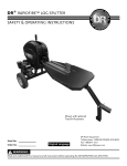
DR® DUAL-ACTION GAS LOG SPLITTER SAFETY & OPERATING INSTRUCTIONS Serial No. Order No. Original Language DR Power Equipment Toll-free phone: 1-800-DR-OWNER (376-9637) Fax: 1-802-877-1213 Website: www.DRpower.com Read and understand this manual and all instructions before operating the DR Dual-Action Gas Log Splitter. Table of Contents Chapter 1: General Safety Rules............................................................................................................................................................ 3 Chapter 2: Setting Up The DR DUAL-ACTION GAS LOG SPLITTER .................................................................................................. 7 Chapter 3: Operating The DR DUAL-ACTION GAS LOG SPLITTER ................................................................................................... 16 Chapter 4: Maintaining The DR DUAL-ACTION GAS LOG SPLITTER ................................................................................................ 19 Chapter 5: Troubleshooting .................................................................................................................................................................. 24 Chapter 6: DR DUAL-ACTION GAS LOG SPLITTER Road Towable Kit .............................................................................................. 26 Chapter 7: Parts Lists and Schematic Diagrams .................................................................................................................................. 30 Conventions used in this manual This indicates a hazardous situation, which, if not avoided, could result in death or serious injury. This indicates a hazardous situation, which, if not avoided, could result in minor or moderate injury. This information is important in the proper use of your machine. Failure to follow this instruction could result in damage to your machine or property. Serial Number and Order Number A Serial Number is used to identify your machine and is located on the Serial Number Label on your machine. An Order Number is used to check and maintain your order history and is located on the upper left portion of your packing slip. For your convenience and ready reference, enter the Serial Number and Order Number in the space provided on the front cover of this manual. Additional Information and Potential Changes DR Power Equipment reserves the right to discontinue, change, and improve its products at any time without notice or obligation to the purchaser. The descriptions and specifications contained in this manual were in effect at printing. Equipment described within this manual may be optional. Some illustrations may not be applicable to your machine. 2 DR® DUAL-ACTION GAS LOG SPLITTER Chapter 1: General Safety Rules Read this safety & operating Instructions manual before you use the DR DUAL-ACTION GAS LOG SPLITTER. Become familiar with the operation and service recommendations to ensure the best performance from your machine. If you have any questions or need assistance, please contact us at www.DRpower.com or call toll-free 1-800-DR-OWNER (376-9637) and one of our Technical Support Representatives will be happy to help you. Labels Your DR DUAL-ACTION GAS LOG SPLITTER carries prominent labels as reminders for its proper and safe use. Shown below are copies of all the Safety and Information labels that appear on the equipment. Take a moment to study them and make a note of their location on your LOG SPLITTER as you set up and before you operate the unit. Replace damaged or missing safety and information labels immediately. #13758 #18887 # 29395 #29394 CONTACT US AT www.DRpower.com 3 Protecting Yourself and Those Around You This is a high-powered machine, with moving parts operating with high energy. You must operate the machine safely. Unsafe operation can create a number of hazards for you, as well as anyone else in the nearby area. Always take the following precautions when using this machine: Keep in mind that the operator or user is responsible for accidents or hazards occurring to other people, their property, and themselves. Always wear protective goggles or safety glasses with side shields while using the Log Splitter to protect your eyes from possible thrown debris. Avoid wearing loose clothing or jewelry, which can catch on moving parts. We recommend wearing gloves while using the Log Splitter. Be sure your gloves fit properly and do not have loose cuffs or drawstrings. Wear shoes with non-slip treads when using your Log Splitter. If you have safety shoes, we recommend wearing them. Do not use the machine while barefoot or wearing open sandals. Wear long pants while operating the Log Splitter. Use ear protectors or ear plugs rated for at least 20 dBA to protect your hearing. Keep bystanders at least 50 feet away from your work area at all times. Stop the engine when another person or pet approaches. Safety for Children and Pets Tragic accidents can occur if the operator is not alert to the presence of children and pets. Children are often attracted to the machine and the splitting activity. Never assume that children will remain where you last saw them. Always follow these precautions: Keep children and pets at least 50 feet from the working area and ensure they are under the watchful care of a responsible adult. Be alert and turn the machine off if children or pets enter the work area. Never allow children to operate the Log Splitter. Hydraulic Safety High fluid pressures are developed in hydraulic machines. Pressurized hydraulic fluid escaping through a pin hole opening can puncture skin and cause severe blood poisoning. Therefore, the following Instructions should be heeded at all times. Do not operate the unit with frayed, kinked, cracked or damaged hoses, fittings, or tubing. Stop the engine, wait 5 minutes and relieve hydraulic system pressure before changing or adjusting fittings, hoses, tubing, or other system components. Do not change any Log Splitter relief valve settings. They are set at the factory for best Splitter performance and safety. Do not check for leaks with your hand. Leaks can be located by passing cardboard or wood over the suspected area: Look for discoloration. If injured by escaping fluid, see a doctor at once. Serious infection or reaction can develop if proper medical treatment is not administered immediately. Always wear safety glasses to protect your eyes from hydraulic fluid. 4 DR® DUAL-ACTION GAS LOG SPLITTER Safety with Gasoline - Powered Machines Gasoline is a highly flammable liquid. Gasoline also gives off flammable vapor that can be easily ignited and cause a fire or explosion. Never overlook the hazards of gasoline. Always follow these precautions: Never run the engine in an enclosed area or without proper ventilation as the exhaust from the engine contains carbon monoxide, which is an odorless, tasteless, and deadly poisonous gas. Store all fuel and oil in containers specifically designed and approved for this purpose and keep away from heat and open flame, and out of the reach of children. Replace rubber fuel lines and grommets when worn or damaged and after 5 years of use. Fill the gasoline tank outdoors with the engine off and allow the engine to cool completely. Don't handle gasoline if you or anyone nearby is smoking, or if you're near anything that could cause it to ignite or explode. Reinstall the fuel tank cap and fuel container cap securely. If you spill gasoline, do not attempt to start the engine. Move the machine away from the area of the spill and avoid creating any source of ignition until the gas vapors have dissipated. Wipe up any spilled fuel to prevent a fire hazard and properly dispose of the waste. Allow the engine to cool completely before storing in any enclosure. Never store a machine that has gas in the tank, or a fuel container, near an open flame or spark such as a water heater, space heater, clothes dryer or furnace. Never make adjustments or repairs with the engine running. Shut down the engine, disconnect the spark plug wire, keeping it away from the spark plug to prevent accidental starting, wait 5 minutes before making adjustments or repairs. Never tamper with the engine’s governor setting. The governor controls the maximum safe operation speed and protects the engine. Over-speeding the engine is dangerous and will cause damage to the engine and to the other moving parts of the machine. If required, see your authorized dealer for engine governor adjustments. Keep combustible substances away from the engine when it is hot. Never cover the machine while the muffler is still hot. Do not operate the engine with the air cleaner or the carburetor air intake cover removed. Removal of such parts could create a fire hazard. Do not use flammable solutions to clean the air filter. The muffler and engine become very hot and can cause a severe burn; do not touch. Towing (optional Road Tow Kit) ALWAYS check before towing to make certain your splitter is correctly and securely attached to the towing vehicle. Be sure that the ball hitch you are using is the proper size for the hitch coupler on the splitter. Be sure the safety chains are properly hooked to the vehicle leaving enough slack for turning. ALWAYS raise the jack to the highest setting before transporting the splitter. ALWAYS use accessory lights and devices when transporting on a road or highway to warn operators of other vehicles. Check your local government regulations for DOT information. ALWAYS allow for added length of the splitter when turning, parking, crossing intersections, and in all driving situations. ALWAYS be careful when backing up. You could jackknife your splitter if care is not taken. ALWAYS travel slowly over rough terrain, on hillsides, and around curves to prevent tipping. NEVER exceed 30 mph. when towing your splitter. Obey all state and local regulations when towing on state and local roads and highways. Adjust your speed for terrain and conditions, as needed. Be extra cautious when towing over rough terrain, especially over a railroad crossing. NEVER allow anyone to sit or ride on your splitter. NEVER carry any cargo on your splitter. NEVER tow the splitter near the edge of a ditch. CONTACT US AT www.DRpower.com 5 General Safety Operating this Log Splitter safely is necessary to prevent or minimize the risk of death or serious injury. Unsafe operation can create a number of hazards for you. Always take the following precautions when operating this Log Splitter: Your Log Splitter is a powerful tool, not a plaything. Exercise extreme caution at all times. The machine is designed to split logs. Do not use it for any other purpose. Know how to stop the Log Splitter quickly; see “stopping the engine” in chapter 3. Never operate your unit on a slippery, wet, muddy, or icy surface. Exercise caution to avoid slipping or falling. See manufacturer’s instructions for proper operation and installation of accessories. Only use accessories approved by DR Power Equipment. Never use the machine without ensuring that all guards and shields are in place. Never, under any conditions, remove, bend, cut, fit, weld, or otherwise alter standard parts on the Log Splitter. This includes all shields and guards. Modifications to your machine could cause personal injuries and property damage and will void your warranty. Allow only one person to operate the Log Splitter at any time. If the machine should start making an unusual noise or vibration, shut down the engine, disconnect the spark plug wire, keeping it away from the spark plug to prevent accidental starting, wait 5 minutes for machine to cool down, then inspect for damage. Vibration is generally a warning of trouble. Check for damaged parts and clean, repair and/or replace as necessary. Never tamper with safety devices. Check their proper operation regularly. Before performing any maintenance or inspection procedure on the Log Splitter shut down the engine, disconnect the spark plug wire keeping it away from the spark plug to prevent accidental starting, wait 5 minutes for machine to cool down. Never allow people who are unfamiliar with these instructions to use the Log Splitter. Allow only responsible individuals who are familiar with these rules of safe operation to use your machine. Never overload or attempt to split logs beyond the manufacturer’s recommendation. Personal injury or damage to the machine could result. While using the Log Splitter, don't hurry or take things for granted. When in doubt about the equipment or your surroundings, stop the machine and take the time to look things over. Never operate the machine when under the influence of alcohol, drugs, or medication. Use the machine only in daylight. Stay alert for hidden hazards or traffic. Keep all nuts and bolts tight and keep the equipment in good operating condition. A Note to All Users Under California law, and the laws of some other states, you are not permitted to operate an internal combustion engine using hydrocarbon fuels without an engine spark arrester. This also applies to operation on US Forest Lands. All DR® Dual-action gas log splitters shipped to California, New Mexico and Washington State are provided with spark arresters. Failure of the owner or operator to maintain this equipment in compliance with state regulations is a misdemeanor under California law and may be in violation of other state and/or federal regulations. Contact your State Park Association or the appropriate state organization for specific information in your area. No list of warnings and cautions can be all-inclusive. If situations occur that are not covered by this manual, the operator must apply common sense and operate this DR® Dual-action gas log splitter in a safe manner. Contact us at www.DRpower.com or call 1-800-DR-OWNER (376-9637) for assistance. 6 DR® DUAL-ACTION GAS LOG SPLITTER Chapter 2: Setting Up The DR DUAL-ACTION GAS LOG SPLITTER It may be helpful to familiarize yourself with the controls and features of your DR Dual-Action Gas Log Splitter as shown in Figure 1 before beginning these procedures. If you have any questions at all, please feel free to contact us at www.DRpower.com. DR DUAL-ACTION GAS LOG SPLITTER Controls and Features Splitting Wedge Log Tray Dipstick/Hydraulic Fluid Fill Pneumatic Tires Operator Lever Jack Tow Hitch Oil Fill Maintenance Meter (option) Fuel Shut-off Gas Fill Key Switch Choke Lever Starter Cord Throttle Lever Figure 1 CONTACT US AT www.DRpower.com 7 Specifications Engine Bed height Wedge Log Trays Force/Tonnage Log Length Log Diameter* Cycle Time Wheels & Tires Weight Dimensions Cylinder Size Hydraulic Tank Pump Control Valve Hydraulic Fluid Manual Start Refer to Engine Manufacturers User Manual for Engine Specifications 24" (610mm) 6.61" (168mm) h, .75" (19mm) w high carbon steel. 27.45in (697mm) L x 11.45in (290mm) W 15 ton 20 inches 30 inches Approx. 11 seconds Dot Approved, 4.8/4-8, Steel Wheel With Taper Roller Bearings Electric Start Refer to Engine Manufacturers User Manual for Engine Specifications 24" (610mm) 6.61" (168mm) h, .75" (19mm) w high carbon steel. 27.45in (697mm) L x 11.45in (290mm) W 15 ton 20 inches 30 inches Approx. 11 seconds Dot Approved, 4.8/4-8, Steel Wheel With Taper Roller Bearings 328 lbs (150kg) 64"L X 40.5"W X 38.5"H 3" (76mm) Bore, 18.51" (470mm) Stroke 6 Quarts Single Stage, 2.84Gal/min (10 L/minute) Integrated Pressure Relief See Table-1 on page 10 336 lbs (153kg) 64"L X 40.5"W X 38.5"H 3" (76mm) Bore, 18.51" (470mm) Stroke 6 Quarts Single Stage, 2.84Gal/min (10 L/minute) Integrated Pressure Relief See Table-1 on page 10 *The diameter listed is indicative of the maximum suggested size - a small log can be difficult to split when it contains knots or a particularly tough fiber. On the other hand, it may not be difficult to split logs with regular fibers even if its diameter exceeds the maximum indicated above. Assembling the DR DUAL-ACTION GAS LOG SPLITTER Tools and Supplies Needed: Two 3/4" Wrenches 1-1/2" Wrench Pliers Soft Face Hammer Two 1/2" Wrenches 7/8" Wrench 8 DR® DUAL-ACTION GAS LOG SPLITTER 17mm Wrench Two 7/16" Wrenches Jack Stands Utility Knife Wire Cutters Safety Glasses 1. Open the Parts Box and lay them out on a clean flat area (Figure 2). 1 Note: For assembly location, the part numbers in the following list can be referenced to the Parts List and illustrations in Chapter 6. 2 Parts Box (Figure 2): Item # Part # Description Qty 1 ............. 13443 .............. Bolt, HCS, 5/16-18 X 1-1/2, Gr5, ZP .............. 4 2 ............. 11238 .............. Washer, Flat, 1/4" USS .................................. 12* 3 ............. 11076 .............. Nut, Nylon Lock, 5/16-18, ZP ........................ 4 4 ............. 29054 .............. Mount, Tow Hitch, Rear................................. 1 5 ............. 29367 .............. Dipstick ........................................................... 1 6 ............. 27610 .............. Abrasion Resistant Sheathing, 15.5in............ 1 7 ............. 11214 .............. Cable Tie, 7-1/2 Long ..................................... 2 8 ............. 25616 .............. Hyd Adapter jcm08-obm08-90 ....................... 1 9** ......... 24230 .............. Strap, Battery .................................................. 1 10** ....... 29365 .............. Mount, Battery................................................ 1 11** ....... 11149 .............. Bolt, HCS, 1/4-20 X 1.00, GR5, ZP ................ 2 12** ....... 11073 .............. Nut, Nylon Lock, 1/4-20, ZP .......................... 2 13** ....... 13447 .............. Battery, 12V, 9AH ........................................... 1 14 ........... 15192 .............. Pin, Hitch Clip, 5/16" - 3/8" ........................... 4 15 ........... 25311 .............. Pin, Cotter, 3/16" X 2.5"................................. 2 16 ........... 25310 .............. Nut, Slotted, 1-14, ZP..................................... 2 17 ........... 25318 .............. Cap, Dust ........................................................ 2 18 ........... 11075 .............. Nut, Nylon Lock, 3/8-16, ZP .......................... 4 19 ........... 11241 .............. Washer, Flat, 5/16 USS, ZP ........................... 4 20 ........... 29377 .............. Clamp, 2 inch, Jack ......................................... 2 21 ........... 29378 .............. U-bolt, 3/8-16 X 2 X 4, ZP .............................. 2 5 4 3 7 21 6 20 19 17 18 14 16 15 13 12 8 2 9 11 10 Figure 2 * Quantity of 8 for manual start Engine. ** Electric Start only. Compare the contents of the Parts Box, Product Pack and Shipping Box with the “Parts Supplied” list above. If you have any questions please contact us at www.DRpower.com or call 1-800-DR-OWNER (376-9637) for assistance. Assembly We recommend two people when handling assemblies during the following procedures. The assemblies involved are heavy and could cause injury when lifting or if dropped. 1. Position the Beam at the center of the pallet and lay it on its side to remove the four sets of Bolts, Flat Washers and Locknuts where the Axle assembly attaches (Figure 3). 2. Set the Beam assembly onto the Axle assembly and align the holes (Figure 4). 3. Insert the four Bolts, Flat Washers (outside of main Beam) and Locknuts and tighten with two 3/4" Wrenches. Bolts, Washers and Locknuts Figure 3 Beam Assembly Bolts, Flat Washers and Locknuts Axle Assembly Figure 4 CONTACT US AT www.DRpower.com 9 4. Place Jack Stands under the Axle assembly to allow room to install the Wheels. 5. Place a Wheel onto the Axle with the Valve Stem facing out and the loose Tapered Bearing on the outside (Figure 5). Note: Make sure the rollers of the Tapered Bearing are facing in. The Hub and Bearing were greased at the factory. Do not remove the grease. Taper Bearing 6. Install the Castle Nut onto the Axle Threads with a 1-1/2" Wrench until the Tapered Bearing is just pushing against the inside of the Wheel Hub but not too tight (Figure 6). There should be minimal amount of drag on the Wheel when rotated by hand. Figure 5 7. Turn the Castle Nut back only as far as needed to align the closest slot in the Nut with the Hole in the Axle. Insert the Cotter Pin and bend the ends around with Pliers to secure the Nut. Check that the wheel will rotate freely and does not wobble on the axle. Castle Nut Cotter Pin Figure 6 8. Install the Dust Cap with a soft face Hammer (Figure 7). 9. Repeat steps 5 thru 8 for the second Wheel. 10. Use a Jack Stand to raise the front of the Splitter allowing room for installing the Tow Hitch and Jack. 11. Remove the six sets of hardware (three per side) that are installed at the front of the Beam assembly (Figure 8). 12. Position the Tow Hitch and secure the right side with three sets of the Bolts, Lock Washers and Locknuts and one set on the left side using two 3/4" Wrenches (Figure 9). Dust Cap 13. Install the Jack, Spacers and U-Bolts with the lower Clamp and U-Bolt located between the two positioning rings of the Jack Housing (Figure 10). Figure 7 Note: The Jack must be installed at a 45° angle for Handle clearance. Temporarily install a Tray as a guide for checking Handle clearance. 14. Secure the U-Bolts with Flat Washers and Locknuts using a 9/16" Wrench. 15. Remove the Jack Stand and roll the Splitter from the Pallet. Bolts, Washers and Locknuts (both sides) Jack Figure 8 U-Bolt Leave These Out Tow Hitch Assembly Clamp Hitch Pin Figure 10 Figure 9 10 Tray DR® DUAL-ACTION GAS LOG SPLITTER Position Rings Note: The Slots of the Engine Mount are for Gas Engine mounting and the round holes are for Electric Motor mounting. 16. Position the Engine onto the Bracket and align the Engine Base holes with the slots of the Bracket (Figure 11). 17. Electric Start only: Route the Harness down to the front left corner of the Engine and connect the green wire ground Terminal of the Harness to the Engine mounting flange with a Bolt, Flat Washers (top and bottom) and Locknut using two 1/2" Wrenches (Figure 12). 18. Install the four sets of Bolts, Flat Washers (top and bottom) and Locknuts using two 1/2" Wrenches to secure the Engine to the Mount (remaining three sets for electric start). Note: Remove protective Caps as needed for the following Hydraulic Hose connections. Figure 11 Hole Engine Hardware Engine Mount Wire Harness 19. Install the Elbow Hydraulic Fitting into the Tank assembly by hand until it cannot be turned any more with your hand. If needed, turn the Elbow back to align it parallel with the ground and facing out (Figure 13). Ground Terminal 20. Tighten the Elbow Jam Nut against the Tank with a 7/8" Wrench. 21. Use Wire Cutters to cut the Cable Ties holding the Hydraulic Hoses together. 22. Install the Fluid Suction Hose onto the Pump and Tank fittings using a 7/8" Wrench.4 Figure 12 Elbow 23. Slide the Sheathing over one of the Pressure Hoses and secure it to the Hose with a Cable Tie near each end (Figure 14). Jam Nut Note: When installing the following Hose fittings they should be tight, but try not to over tighten. Start with a snug fit and if leaking is detected then tighten a bit more until no leaks are detected. Pump 24. Install the Hose with Sheathing to the Control Valve (long elbow end) and Pump using a 7/8" Wrench. 25. Install the Fluid Return Hose (long elbow end) at the Control Valve and the top of the Tank using a 7/8" Wrench (Figure 15). Long Elbow Suction Hose Figure 13 Fluid Return Hose Long Elbow Cable Tie Pressure Hose Control Valve Sheathing Pump Tank Figure 15 Cable Tie Figure 14 CONTACT US AT www.DRpower.com 11 26. Install Hydraulic Cap/Dipstick into the hole on top of the Tank (Figure 16). 27. Remove the Nut and Flat Washer from the Control Lever threads and reinstall the Nut all the way onto the threads (Figure 17). Hydraulic Cap/Dipstick 28. Place the Washer onto the threads and screw the Control Lever into the top of the Control Valve as far as it will go. Turn it back to the desired position depending of your preference to split on the right or left side of the splitter. Tighten the Jam Nut against the Valve to secure the Lever using a 17mm Wrench. 29. Install the Trays onto the sides of the Beam assembly by aligning the legs with the receiving tubes and secure with the Hitch Clips (Figure 18). Figure 16 Control Lever 30. Remove the two left side Bolts, Flat Washers and Locknuts from the Tank and Axle using two 3/4" Wrenches. Position the Tow Bracket and secure with the hardware you just removed (Figure 19). 31. Raise the Jack so the Wood Splitter is parallel with the ground. 32. The following steps are for Electric Start only: Position the Battery Mount and Hold down under the Engine and install a Bolt, Washer (each side) and Locknut closest to the axle by hand (Figure 20). Jam Nut Flat Washer 33. Place the battery into the Hold Down with the Terminals facing to the rear of the Splitter. 34. Rotate the Mount and Battery into position and install the second mounting Bolt, Washer (each side) and Locknut. Tighten both sets of Hardware using two 7/16" Wrenches (Figure 21). Figure 17 35. Install the red positive Terminal to the Battery. Do not install the Negative Terminal at this time. Trays Receiving Tubes Hardware Battery Hold Down Figure 18 Battery Mount Figure 20 Hold Down Positive Terminal Bolts, Washers and Locknuts Tow Bracket Figure 19 Battery Mount Figure 21 12 DR® DUAL-ACTION GAS LOG SPLITTER Bolts and Locknuts Adding Oil and Gasoline Engine Oil Refer to Engine Manufacturers User Manual for Engine Oil type and quantity Fuel Unleaded gasoline NOTE: Use only the recommended High Detergent Engine Oil. Other types of oil could cause problems operating your machine. Please refer to your Engine Owner’s Manual for detailed oil information. Oil Check/Fill Gas Cap The Frame and Engine must be level to get an accurate reading when adjusting the oil level. Use the Jack to adjust the height of the Log Splitter to level the Frame. 1. Position the machine so the Frame and Engine are level. Remove the Oil Fill/Dipstick (Figure 22) and clean the end of it with a rag. 2. Machines are shipped with no oil. Initially add 16 oz. of the oil recommended by the Engine Manufacturer. Wait one minute for the oil to settle. Figure 22 3. Replace the Dipstick, and screw it in to ensure an accurate reading and then remove it to check the oil level (clean the Dipstick with the rag after checking). 4. Continue adding a few ounces of oil at a time, rechecking the Dipstick until the oil reaches the fill mark. Be careful not to overfill. 5. Replace the Dipstick and screw all the way down when full. 6. Remove the Gas Fill Cap and fill the Gas Tank with fresh, unleaded gas (with a minimum of 85 Octane) to approximately 1" to 1-1/2" below the top of the fill neck to allow for fuel expansion. Be careful not to overfill and reinstall the Gas Fill Cap before starting the engine. See your Engine Owner’s Manual for more detailed information. NOTE: To refill the Gas Tank, turn the engine OFF and let the engine cool at least five minutes before removing the Gas Fill Cap. CONTACT US AT www.DRpower.com 13 Adding Hydraulic Fluid Hydraulic Fluid Fill Cap Tools and Supplies Needed: Paper Towels Hydraulic Fluid (see table-1) Fluid Half Way on the Steel Rod Figure 23 HYDRAULIC OIL ISO RECOMMENDATIONS ISO 68 ISO 46 ISO 32 ISO 22 You must add hydraulic fluid before using the splitter. This machine is shipped without hydraulic fluid in the hydraulic tank. When performing the following procedures, fill the hydraulic tank slowly, checking the level frequently to avoid overfilling. To get an accurate reading when checking the hydraulic fluid level: - the machine should be on a level surface. - the dipstick should be pushed in fully to ensure an accurate fluid level reading. TIP: Check the Fluid level by removing the Hydraulic Fluid Filler Cap and wiping the steel rod of the Dipstick with a Paper Towel. Reinsert the Cap fully (Figure 23). Remove the Cap and lay the Steel Rod onto a dry Paper Towel and read the level by the wet mark that is transferred from the Steel Rod to the Paper Towel. 7. Remove the Hydraulic Fluid Fill Cap Dipstick and fill the Hydraulic Tank with the recommended fluid (see table-1). 0° 10° 20° 30° 40° 50° 60° 70° 80° 90° (-18°) (-12°) (-7°) (-1°) (4°) (10°) (16°) (21°) (27°) (32°) TEMPERATURE FAHRENHEIT (CELSIUS) Table-1 NOTE: The Tank is full when the fluid level is within the recommended level on the Dipstick. The recommended level is in the middle of the two marks on the Steel Rod. Do not deviate past the marks up or down from that point. If the fluid level is not within this range, fluid must be added or removed to bring it within that range. NOTE: The operator should initially only need to add about 5 quarts before checking the level because some fluid has already been added to the Cylinders. 8. Start the Engine and cycle the cylinder several times (see “Operating Your DR Dual-Action Log Splitter”, Chapter 3). 9. Retract the Cylinder, shut off the Engine and recheck Fluid level. 10. Adjust level as needed. 14 DR® DUAL-ACTION GAS LOG SPLITTER Check the Tire Pressure Tools Needed: Tire Pressure Gauge Air Compressor Do not over inflate the tires. Inflate to the manufacturers recommended pressure found on the tires. Valve Stem Protective Cap 1. Remove the Valve Stem Protective Cap (Figure 24) and check the Tire pressure with a Tire Pressure Gauge. 2. Check what the manufacturers recommended pressure is that is stamped on the side of the Tire. 3. If the pressure is too low, add air through the Valve Stem with an air hose. 4. Replace the Valve Stem Protective Cap when finished. Figure 24 Connecting the Battery (electric start models) 1. Connect the Black Negative Terminal onto the negative Battery Lug (Figure 25). Negative Battery Lug Negative Terminal Figure 25 CONTACT US AT www.DRpower.com 15 Chapter 3: Operating The DR DUAL-ACTION GAS LOG SPLITTER It may be helpful to better familiarize yourself with the features of your Log Splitter by reviewing Figure 1 in Chapter 2 before beginning the steps outlined in this chapter. Operator Zone Operator Zone TOP VIEW Figure 26 Read and understand all instructions, safety precautions, and/or warnings listed in “Chapter 1 General Safety Rules” before operating this DR Dual-action gas log splitter. If any doubt or question arises about the correct or safe method of performing anything found in this manual, please contact our Customer Service Representatives at our toll free number: 1-800-DR-OWNER (376-9637). When operating the Log Splitter, make sure you are standing in the safe operating area (OPERATOR ZONE) (Figure 26). You must stay in the safe operating area at all times when the splitting wedge is in motion (whether extending or retracting). Never place any part of your body into a position that causes an unsafe operating condition. Before loading and operating the Log Splitter, always wear protective gear, INCLUDING safety goggles, hearing protection, tight-fitting gloves without draw strings or loose cuffs, and steel-toed shoes. Use the following photos for the correct and incorrect methods of splitting logs. Never split a log using an incorrect or unsafe method. Starting Choke Control Lever Fuel Shut-off Valve 1. Position your Log Splitter on flat, dry ground and block the two back Wheels and the Jack Wheel to prevent it from moving. Throttle Control Lever 2. Make sure the Fuel Shut-Off Valve is in the “ON” position (Figure 27). 3. Move the Choke Control Lever to the “CHOKE” position (should only be needed if the Engine is cold). 4. Move the Throttle Control Lever to the fast (rabbit) position. Key Switch Recoil Starter Handle Figure 27 5. Manual Start: Turn the Ignition Switch to the “On” position. Grasp the Recoil Starter Handle and slowly pull until you feel resistance. Let the Cord retract a little bit then pull the Cord rapidly to start the Engine. One or two pulls usually starts the Engine. Electric Start: Turn and hold the Key in the start position until Engine starts then let the Key return to run position. 6. Move the Choke Control Lever (if used for cold engine) back to the “RUN” position when the Engine is running well. 7. If the Log Splitter has not been running (cold engine), warm up the Engine and Hydraulic System by running the Engine at half throttle for 3 to 4 minutes, then advance the Engine Throttle Control to maximum speed for splitting. Stopping 1. Move the Throttle Lever to Idle. 2. Manual Start: Turn the Ignition Switch to the “Off” position (Figure 27). 3. Electric Start: Turn the Key to the Off position. 16 DR® DUAL-ACTION GAS LOG SPLITTER Splitting Note: All logs should be no longer than 20". Do not place your hands on the ends of the log when loading the Log Splitter. This is a very UNSAFE method and could result in injury to your hands (Figure 28). Do not reach or step across the rail while the Log Splitter is running. This is a very UNSAFE method which could cause personal injury or even death. Figure 28 Never attempt to split wood across the grain. The Log Splitter was not designed for cross-grain splitting. Doing so could damage the Log Splitter and may cause personal injury (Figure 29). Make sure both ends of the log you are splitting are cut as square as possible. This will prevent the log from sliding out of position while under pressure (Figure 30) Never run the Log Splitter unless the hydraulic fluid tank is at the proper level. Figure 29 1. Place the log on the Log Splitter. Grasp the log on the sides near the middle of the block (Figure 31). Center the log, side-to-side, on the rail of the Log Splitter, making sure that one end is against the Stop Base. 2. Using only your hand, push the Valve Control Handle forward (towards the log) (Figure 32). If the log moves before it is contacted by the Wedge, release the Valve Control Handle and then reposition the log. Figure 30 Valve Control Handle Hands on Sides of Wood Wedge Wood Against Stop Base Figure 32 Figure 31 CONTACT US AT www.DRpower.com 17 If the log does not split immediately, do not continue the forward thrust of the ram for more than five (5) seconds. This can damage the splitter. Try repositioning the log on the splitter or set the log aside. 3. Hold the Valve Control Handle, moving the Wedge towards the Log until the log is split or the Cylinder Rod stops at its maximum travel position. Stop the Log Splitter (forward movement), at any point in the splitting process, if you feel an unsafe splitting condition is occurring. As the log is being split, DO NOT reach forward and attempt to catch the split wood — let it fall to the Tray. 4. Once the Wedge reaches its full forward travel, let go of the Valve Control Handle and the Wedge will stay at that position. 5. Load another log on the other side of the Wedge and pull the Valve Control Handle, moving the Wedge towards you and the Log until the log is split or the cylinder rod stops at its maximum travel position. Depending on the type of wood being split, a log may not always split into two pieces and fall onto the trays. If a log sticks to the wedge, move the Wedge away from the Base, stop the engine, and carefully remove the log from the wedge. If the Log is stuck onto the Wedge and you can’t remove it by hand, a piece of wood cut into a wedge shape can be used between the Log and Base to lift the Log from the machine as you actuate the Lever. Splitting Large Logs When splitting a large log, or one in which the wood is extremely tough or stringy (such as elm), the first pass through the Splitter may not split the log into two sections. If this happens, turn the log and split off small sections. Repeat this process as necessary to split the entire log. 18 DR® DUAL-ACTION GAS LOG SPLITTER Chapter 4: Maintaining The DR DUAL-ACTION GAS LOG SPLITTER Regular maintenance is the way to ensure the best performance and long life of your machine. Please refer to this manual and the engine manufacturer's owner's manual for maintenance procedures. Service intervals listed in the checklist below supersede those listed in the engine manufacturer's owner's manual. Before performing any maintenance procedure or inspection, stop the engine, wait five (5) minutes to allow all parts to cool. Disconnect the spark plug wire, keeping it away from the spark plug. Disconnect the Battery Terminals (Electric start only). Regular Maintenance Checklist PROCEDURE Check Engine Oil Level Check the general condition of the Log Splitter (e.g. nuts, bolts, welds, etc). Check the Wedge for smooth travel and sharpness Check the Hydraulic Fluid level (See “Adding Hydraulic Fluid” in Chapter 2) Check Tire Pressure Clean Engine Exterior and Cooling Fins Change Engine Oil Replace Air Filter Change Hydraulic Fluid Replace Spark Plug BEFORE EACH USE EVERY 25 HOURS EVERY 100 HOURS ▲ ▲ ▲ ▲ Before towing 1st time 5 hours ▲ ▲ ▲ ▲ 1st Time 25 Hours ▲ ▲ General Maintenance Check (before operating) The hydraulic system (Hoses, Cylinder, and Pump) should be carefully inspected before each use. Also, inspect the mechanical parts at the same time. Make sure all Clamps, Nuts, Bolts, Fittings, etc. are properly installed and tightened. Do not check for leaks with your hand. Leaks can be located by passing a piece of cardboard or wood around the suspected leak and looking for discoloration. High-pressure fluid escaping from a very small hole can be almost invisible. Escaping fluid under pressure can have sufficient force to penetrate skin, causing serious injury or even death. If fluid is injected into your skin, it must be treated immediately by a doctor familiar with this type of injury. Always replace frayed, kinked, or cracked hoses and/or other damaged hydraulic components with DR Power Equipments authorized parts and components specified in the “Parts” section (Chapter 7) of this manual. Replacement parts from secondary suppliers (not original DR Power Equipments replacement parts) can lead to product damage and/or personal injury, and will void the warranty. Do not remove the cap from the hydraulic tank or reservoir while the Log Splitter is running. Hot fluid, under pressure, could be expelled resulting in serious injury. Should it become necessary to loosen or remove any Hydraulic Fitting or Line, be sure to relieve all hydraulic pressure by shutting off the Engine, removing the Spark Plug Wire, and moving the Valve Control Handle back and forth several times until no cylinder movement is visible. CONTACT US AT www.DRpower.com 19 Engine Service Refer to the engine manufacturer’s manual for engine maintenance, repair and storage. Hydraulic Fluid Change Tools and Supplies Needed: Adjustable Wrench Clean Rags Approved Container (8 quart capacity) Small funnel Dipstick Screen Filter Inlet Hose to Pump Inlet Hose to Tank Figure 33 Never run the Log Splitter unless the hydraulic fluid tank is at the proper level. Hydraulic Fluid Specifications See Table-1 on page 10. 1. Drain the hydraulic tank. a. b. Filter Screen Elbow Figure 34 c. d. e. f. g. h. i. Place an approved Container under the Inlet Hose. Disconnect the Inlet Hose at the Pump Elbow using an Adjustable Wrench and lower the Hose to drain the Fluid into the Container (Figure 33). Remove the Hydraulic Fluid Dipstick to let air in to improve fluid flow. Completely drain the Tank. Disconnect the Inlet Hose at the Tank Elbow using an Adjustable Wrench. Remove the Screen (with elbow) from the Tank with an Adjustable Wrench and clean any debris from the Screen or replace as needed (Figure 34). Reinstall the Screen (with elbow). Reconnect the Inlet Hose at the Tank Elbow using an Adjustable Wrench. Reconnect the Inlet Hose at the Pump Elbow using an Adjustable Wrench. 2. Refill the hydraulic tank. a. b. Remove the Hydraulic Fluid Dipstick from the Hydraulic Tank (Figure 33). Fill the Hydraulic Tank as described in the “Adding Hydraulic Fluid” section in Chapter 2. 3. Start the engine and cycle the cylinder. a. b. c. d. Replace the Spark Plug and Spark Plug Wire. Start the engine and cycle the Cylinder several times (see “Operating Your Log Splitter”, Chapter 3). Retract the Cylinder and shut off the engine. Recheck the Hydraulic Tank to make sure fluid is up to the proper level. Hydraulic Fluid Capacities Hydraulic Tank . . . . . . . 6 quarts (5.6 liters) 20 DR® DUAL-ACTION GAS LOG SPLITTER Replacing the Wheels Tools and Supplies needed: Dust Cap Channel lock Pliers Clean Rags Adjustable Wrench Needle Nose Pliers Jack and Jack Stands Soft FaceHammer 1. Jack the Splitter off the ground and secure with Jack Stands. 2. Remove the Dust Cap from the Wheel Assembly with Channel Lock Pliers (Figure 35). Figure 35 3. Straighten the ends of the Cotter Pin with Needle Nose Pliers so the Cotter Pin can be pulled from the hole in the Axle (Figure 36). 4. Remove the Castle Nut with the Channel Lock Pliers. 5. Pull the Wheel assembly and Taper Bearing from The Axle (Figure 37). 6. Slide a Wheel Assembly onto the Axle Shaft. Make sure the open side of the Wheel Hub with the loose Taper Bearing is facing towards you. Castle Nut Cotter Pin Figure 36 7. Screw the Castle Nut onto the Axle and tighten it with an Adjustable Wrench to seat the Bearings (Figure 36). 8. Back the Castle Nut off and then snug it up to the Bearing lightly. 9. Insert a Cotter Pin through the slots of the Castle Nut and into the hole in the Axle. 10. Bend the ends of the Cotter Pin with Needle Nose Pliers to secure it. 11. Place the Dust Cap onto the Wheel Assembly Hub and work it into the Hub using a soft face Hammer (Figure 35). 12. Jack the back of the Splitter up and remove the Jack Stands. 13. Lower the Splitter to the ground. Taper Bearing Figure 37 CONTACT US AT www.DRpower.com 21 Battery Care (electric start models) Proper care can extend the life of a Battery. Follow these recommendations to ensure your Battery’s best performance and long Battery life: When you are finished charging the battery, disconnect the charger from the outlet first, then disconnect the battery charger wires from the battery. If you leave the battery charger wires connected to the battery, the battery will discharge itself back into the charger. Do not allow the Battery charge to get too low. If the machine is not used, charge the Battery every 4 – 6 weeks. Operate the engine for at least 45 minutes to maintain proper Battery charge. Store an unused Battery in a dry environment with temperatures between +40°F (+5°C) and +95°F (+35°C). Make sure the storage temperatures will never be outside of these limits. The lower the storage temperature is within the specified temperature, the better as the Battery will discharge more slowly at low temperatures. Do not charge an already charged Battery. In theory, you cannot overcharge our Battery with a Trickle Charger; however, when a Battery is fully charged and the Charger is still on, it generates heat that could be harmful to the Battery. A fully charged Battery will read 12V-13.2V with a Voltmeter. Do not continue to crank your Engine when the Battery charge is low. Charging the Battery Operate the Engine for at least 45 minutes to maintain proper Battery charge. If the Battery loses its charge, you will need to use a Trickle Charger (like the DR Battery Charger) to recharge it. The Charger should have an output of 12 volts DC at no more than 2 amps. At 1 amp the Battery may need to be charged for as long as 48 hours. At 2 amps, the Battery may need to be charged for as long as 24 hours. NOTE: Using the Recoil Starter and then running the Engine will not recharge a dead or significantly discharged Battery. To connect a Battery Charger to your DR DUAL-ACTION GAS LOG SPLITTER, follow the steps listed below. 1. Attach the Black (-) alligator clipped wire from the Charger Adapter to the Negative (-) terminal of the Battery, then attach the Red (+) alligator clipped wire to the Positive (+) Battery terminal. 2. Plug the Charger into a standard wall outlet. 22 Typically, the Battery takes between 6 and 8 hours to fully charge. Do not leave the charger on the Battery longer than 24 hours for a 2 amp charger, or 48 hours for a 1 amp charger as you could potentially damage the Battery.. You can charge the Battery many times. The Battery lasts longer if you charge it before it is fully drained. Keep it fully charged and at room temperature when not using your DR DUAL-ACTION GAS LOG SPLITTER. If the Battery does not hold its charge for very long under normal conditions or it simply won’t hold a charge, then replace it. You can purchase replacement Batteries directly from us. To install your new Battery, follow the directions below. DR® DUAL-ACTION GAS LOG SPLITTER Replacing the Battery Tools Needed: Battery Clamp Terminals Two 7/16" Wrenches 1. Disconnect the Battery Terminals (Figure 38). 2. Remove the Bolts and Locknuts that secure the Battery Clamp using two 7/16" Wrenches. 3. Remove the Clamp, Bracket and the dead Battery. 4. Position the new Battery onto the Bracket. 5. Install the Battery Clamp and secure with the Bolts and Locknuts using two 7/16" Wrenches. Battery Bracket Bolts and Locknuts Figure 38 6. Attach the Battery Terminals. Black Wire to negative black Terminal and Red Wire to positive red Terminal. Disposing of the Battery Responsibly The Battery is a sealed lead-acid Battery. Recycle or dispose of it in an environmentally sound way. Do not dispose of a Lead-Acid Battery in a fire; the Battery may explode or leak. Do not dispose of a Lead-Acid Battery in your regular, household trash. Law in most areas prohibits incinerating, disposing in a landfill, or mixing a sealed Lead-Acid Battery with household trash. Recycling a Used Battery Please dispose of your used Batteries responsibly by recycling them. Call your local Solid Waste Management District or your local waste handler to locate the collection site nearest you. Some collection sites recycle Batteries year-round; others collect them periodically. You can also visit the Web site of Earth 911 for more information [www.earth911.org]. Once there, click the Municipal HHW link under Hazardous Household Waste, and enter your zip code. The site lists recycling centers located near you. For a fee, you can recycle your Batteries with the International Metals Reclamation Company. Visit them at www.inmetco.com and click Services; or contact them at: INMETCO, One INMETCO Drive, Ellwood City, PA 16117, (724) 758-2800; fax (724) 758-2845 To learn more about hazardous waste recycling, visit the Web site for Battery Council International [www.batterycouncil.org] or for the Environmental Protection Agency [www.epa.gov]. To learn more about hazardous waste recycling, visit the Web site for Battery Council International [www.batterycouncil.org] or for the Environmental Protection Agency [www.epa.gov]. CONTACT US AT www.DRpower.com 23 Chapter 5: Troubleshooting Most problems are easy to fix. Consult the Troubleshooting Table below for common problems and their solutions. If you continue to experience problems, contact us at www.DRpower.com or call toll-free 1-800-DR-OWNER (376-9637) for support. Before performing any maintenance procedure or inspection, stop the engine, wait five (5) minutes to allow all parts to cool. Disconnect the spark plug wire, keeping it away from the spark plug. Troubleshooting Table SYMPTOM POSSIBLE CAUSE With Engine running and the valve control handle is pushed, the wedge does not move or is slow to respond. Air in the system; Bleed any accumulated air from the hydraulic system. The Log Splitter may not be on a level surface. The hydraulic fluid may be low. Check and adjust the level as required. In extreme high temperature and heavy rapid use, the hydraulic fluid may have overheated. Allow the machine to cool. The wood you are splitting may be too hard, it has knots, or its fiber is very tough. Check the high-pressure hose, fittings, and valve openings for dirt and debris that may have obstructed the openings. If the Wedge will still not move or is slow to respond, Visit our website at www.DRPower.com, call 1-800-DR-OWNER (376-9637), or call a qualified hydraulic mechanic for assistance to replace worn components. Be sure to reference Hydraulic Safety in Chapter 1. The engine won’t start. Check that the Fuel Shut-Off Valve is turned ON (See “Operating your WOOD SPLITTER”, Chapter 3). Are you using fresh, clean gas? If the gas is old, change it. Use a fuel stabilizer if you keep gas longer than 30 days. Is the spark plug clean? If the spark plug is dirty or cracked, change it. If it’s oily, leave it out, hold a rag over the plug hole and pull the recoil cord several times to blow out any oil in the cylinder, then wipe off the plug and reinsert it. If your engine still won’t start, contact us at www.DRpower.com for assistance. (Please refer to the engine owner’s manual for engine-specific procedures.) The engine lacks power or is not running smoothly. (Please refer to the engine owner’s manual for engine-specific procedures.) Engine smokes. (Please refer to the engine owner’s manual for engine-specific procedures.) 24 Check that the Throttle Lever is in the fast (rabbit) position. Is the air filter clean? If it’s dirty, change it following the procedure in the engine manufacturer’s owner’s manual. Is the spark plug clean? If it’s fouled or cracked, change it. If it’s oily, leave it out, hold a rag over the plug hole and pull your recoil cord several times to blow out any oil in the cylinder, then wipe off the plug and reinsert it. Are you using fresh, clean unleaded gas? If it’s old, change it. Use a fuel stabilizer if you keep gas longer than 30 days. Does your engine have the right amount of clean oil? If it’s dirty, change it following the procedure in the engine manufacturer’s owner’s manual. Check the oil level and adjust as needed. If your engine still lacks power, contact us at www.DRpower.com for assistance. Check the oil level and adjust as needed. Check the air filter and clean or replace if needed. You may be using the wrong oil—too light for the temperature. Refer to your Engine Owner’s Manual for detailed information. Clean the cooling fins if they’re dirty. If the engine still smokes, contact us at www.DRpower.com for assistance. DR® DUAL-ACTION GAS LOG SPLITTER Troubleshooting Table (Continued) Before performing any maintenance procedure or inspection, stop the engine, wait five (5) minutes to allow all parts to cool. Disconnect the spark plug wire, keeping it away from the spark plug. SYMPTOM POSSIBLE CAUSE The engine stalls when the wedge engages the wood. The engine may not be properly adjusted. Contact us at www.DRpower.com for assistance. Hydraulic fluid squirts from the fill plug during operation. The hydraulic fluid tank may be over-filled. Drain fluid down to the proper level. The LOG SPLITTER is not level. Make sure the LOG SPLITTER is on level ground. CONTACT US AT www.DRpower.com 25 Chapter 6: DR DUAL-ACTION GAS LOG SPLITTER Road Towable Kit Tools and Supplies Needed: Original Tow Hitch Installing the Road Towable Kit Hardware 1. Remove the existing Hitch from the Log Splitter by removing the large Bolt, Washers and Locknut using a 15/16" Wrench and Ratchet with a 15/16" Socket (Figure 39). Figure 39 Hitch Hardware 2. Attach the new Tow Hitch to the Frame with the two 1/2-13 x 4" Bolts and Locknuts using two 3/4" Wrenches (Figure 40). New Tow Hitch 3. Position the Safety Chains at the holes in the Frame and secure with two 3/816 x 1-1/2" Bolts, four Washers (one on Bolt side and one on Locknut side) and Locknuts using two 9/16" Wrenches. Chain Hardware Safety Chains 4. Place the Vehicle Connector end of the Wire Harness near the Tow Hitch and let it extend about two feet past the Hitch. Place the 7/16" Tube Clamp around the Harness and secure the Clamp to the Frame using two 7/16" Wrenches (Figure 41). Note: Make sure there is enough of the Harness past the Tube Clamp to be connected to the tow vehicle. Figure 40 Small Tube Clamp Vehicle Connector This End Figure 41 Tube Clamp Hardware Hose Clamp Figure 42 26 Two 7/16" Wrenches Two 1/2" Wrenches Two 9/16" Wrenches Two 3/4" Wrenches 15/16" Wrench 15/16" Socket with 1/2" Ratchet DR® DUAL-ACTION GAS LOG SPLITTER 5. Guide the other end of the Harness behind the Hitch and under the Frame. Feed the Harness over the center of the Hydraulic Tank so it is at the Back of the machine. 6. Remove a Bolt, Washer and Locknut at the center of the Frame on the Left side with two 9/16" Wrenches (Figure 42). Place the large Tube Clamp over the Harness and secure to the Frame with the Bolt, Washer and Locknut from the kit. Tighten the Clamp Hardware with two 1/2" Wrenches. 7. Assemble the Fenders to the Frame with eight 5/16-18 x 3/4" Carriage Bolts (fender side) and Locknuts using a 1/2" Wrench (Figure 43). Nylon Locknut 8. Position the roadside Tail Light (yellow/brown wires) and curbside Tail Light (green/brown wires) onto the Fenders and secure with one of the 1/420 Locknuts on the outside stud using a 7/16" Wrench. Roadside Fender Carriage Bolts and Locknuts 9. Route the Yellow/Brown Wire Connector with a White Ground Wire behind the Tank on the roadside (left side) of the Log Splitter. 10. Plug in the Connector, place the Ground Wire onto the inner Stud and secure it with a 1/4-20 Locknut using a 7/16" Wrench (Figure 44). 11. Route the Green/Brown Wire Connector with a White Ground Wire behind the Tank on the curbside (right side) of the Log Splitter. Yellow and Brown Wires (roadside) Roadside Tail Light Figure 43 12. Plug in the Connector, place the Ground Wire onto the inner Stud and secure it with a 1/4-20 Locknut using a 7/16" Wrench. 13. Use the Cable Ties to secure the excess Harness to the Engine Mount hole. Secure the center portion of Harness to the two holes in the Frame. Trim all Cable Ties with Wire Cutters. Cable Ties Green and Brown Wires (curbside) White Ground Wire (both sides) Locknut Figure 44 CONTACT US AT www.DRpower.com 27 Attaching to Tow Vehicle Making sure the Splitter is securely attached to the vehicle is the responsibility of the owner/operator. Failure to securely attach the Log Splitter can cause loss of control of the vehicle or the Log Splitter being separated from the towing vehicle, resulting in serious injury or death. ALWAYS use accessory lights and devices when transporting on a road or highway to warn operators of other vehicles. Check your local government regulations. 1. Close the Latch Assembly on the Tow Hitch Assembly to lock the Tow Hitch Assembly onto the Tow Ball (Figure 45). Attach the towing Safety Chains to the Tow Vehicle ensuring there is enough slack for turning. Latch Assembly 2. Make sure the Hitch Coupler is properly and securely attached to the Tow Ball. 3. Insert the Locking Pin into the hole of the Latch Assembly to lock it in the closed position (Figure 46). 4. For extra safety and security, you may want to purchase a Lock to install into the hole of the Latch Assembly. Safety Chains Tow Hitch Assembly 5. Plug the Harness Connector to the Tow Vehicle. Hitch Coupler Adjustment Check Figure 45 1. Place a 2" Ball in the Socket of the Coupler and close the Latch Assembly (Figure 47). Verify that the Locking Trigger is properly engaged in its detent. Locking Pin 2. Pull on the Ball and/or Coupler, trying to remove the Ball from the Socket. If the Ball moves more than 1/16" in the Coupler’s Socket, the Clamp requires adjustment. Follow the proper adjustment procedure in the following steps. Hitch Coupler Adjustment 1. With the proper size Ball in the Socket of the Hitch Coupler, close the Latch of the Coupler completely (Figure 48). Verify that the Locking Trigger is properly engaged in its detent. Latch Assembly 2. Tighten the Locknut on the underside of the Coupler until the Spring between the Nut and the Clamp is fully compressed. Then back off the Locknut 1/2 turn or just enough that the Latch is able to Clamp and Figure 46 unclamp from the Ball. Locking Trigger Pull Spring 1/16" Movement Lock Nut Ball Clamp Figure 47 Figure 48 28 DR® DUAL-ACTION GAS LOG SPLITTER CONTACT US AT www.DRpower.com 29 Chapter 7: Parts Lists and Schematic Diagrams Parts List - FRAME ASSEMBLY NOTE: Part numbers listed are available through DR Power Equipment. Ref# Part# Description Ref# Part# Description 1 2 3 4 5 6 7 8 9 10 11 12 13 Washer, Flat, 5/16", USS Beam Assembly, With Labels Nut, Nylon Lock, 3/8-16 Bolt, HHCS, 1/2-13 X 1.5" Gr5, ZP Washer, SAE Flat, 1/2", ZP Nut, Nylon Lock, 1/2-13 Pin, Snap Safety, 3/8" X 2.75" Dipstick Clevis, Hitch Washer, Flat, 5/8", USS Mount, Tow Hitch, Rear Wheel and Tire Assembly, W/ Dust cap Axle 14 15 16 17 18 19 20 21 22 23 24 25 Reservoir, With Labels Mount, Hitch, Tow Jack, Trailer, Wheeled Bolt, HCS, 5/8-11 X 1.75", Gr5, ZP Washer, .640" ID X 1.5" OD X .25" Nut, Nylon Lock, 5/8-11 U--bolt, 3/8-16 X 2" X 4", ZP Label, DR Logo, 4.0", 4 Color Clamp, 2", Jack Nut, Slotted, 1-14, ZP Pin, Cotter, 3/16" X 2.5" Dust cap 30 11241 29387 11075 22909 23499 11072 21155 29367 19295 15745 29054 25297 29045 DR® DUAL-ACTION GAS LOG SPLITTER 29386 29053 29382 19296 10174 10131 29378 19202 29377 25310 25311 25318 Schematic – FRAME ASSEMBLY CONTACT US AT www.DRpower.com 31 Parts List – BEAM ASSEMBLY NOTE: Part numbers listed are available through DR Power Equipment. Ref# Part# Description Ref# Part# Description 1 2 3 4 5 6 7 8 9 10 11 12 13 14 15 Pin, Hitch Clip, 1/2" To 9/16", .12" Wire Washer, Flat, 5/16", USS Valve, Hyd, 3200 Psi Cylinder Assembly, Hydraulic Bolt, HCS, 5/16-18 X 1" Washer, Lock, Split, 5/16" Nut, Nylon Lock, 1/2-13 Washer, 26mm X 44mm X 3.5mm Bolt, HHCS, 1-14 X 6", Gr5, ZP Washer, SAE Flat, 1/2", ZP Pin, Cotter, 3/16 X 2.5" Hyd Adapter, Jcm06-Obm08 Hyd Adapter, Obm08-Jcsf06 Bolt, HHCS, 1/2-13 X 1.5", Gr5, ZP Nut, Slotted, 1-14, ZP 16 17 18 19 20 21 22 23 24 25 26 27 28 29 30 Brace, Lower Cylinder Guard, Seal Label, DR Branding Label, Warning, Do Not Sit or Stand Tray, Log, With Labels Cover, Valve, With Label Label, Controls Bolt, HCS, 3/8-16 X 5.5", Gr5, ZP Plug, Hour Meter Hole, 2" X 1-1/4" Nut, Nylon Lock, 3/8-16 Washer, Flat, 1/4", USS Bolt, HCS, 5/16-18 X .75" Nut, Nylon Lock, 5/16-18 Handle Assembly, Control Valve O-ring, 22mm X 2.4mm 32 16003 11241 29047 29043 11158 11243 11072 29502 29375 23499 25311 25346 29371 22909 25310 DR® DUAL-ACTION GAS LOG SPLITTER 29046 29370 29519 29395 29389 29388 29394 29373 15131 11075 11238 12321 11076 29513 29503 Schematic – BEAM ASSEMBLY CONTACT US AT www.DRpower.com 33 Parts List – ENGINE AND PUMP ASSEMBLY NOTE: Part numbers listed are available through DR Power Equipment. Ref# Part# Description Ref# Part# Description 1 2 3 4 5 6 7 8 9 10 11 12 13 14 15 Sheathing, Abrasion Resistant, 15.5" Tie, Cable, 7 1/2"L Hyd Adapter, Jcm08-Obm08-90 Hyd Adapter, Jcm06-Obm08 Hyd Adapter, Jcm06-Obm08-90 Hose Assembly, Hyd, Tank-Pump, 12.5" Hose, Hyd, 15" Washer, Flat, 1/4", USS Nut, Nylon Lock, 5/16-18 Filter, Hyd, In tank Bolt, 5/16-18 X 1.5" Set Screw, 1/4-20 X 1/4", Cup Point Coupling, Pump, Hyd, Gas Washer, Lock, Split, 5/16" Bolt, SHCS, 5/16-24 X 1", ZP 16 17 18 19 20 21 22 29048 29049 27627 29507 13447 24230 29397 23 24 25 26 27 28 29 11073 11149 29503 29511 18887 12781 29365 Mount, Pump, Hyd Pump, Hyd, 10L/Min Wire Jumper, B&S, ES Charging Wire Harness, Wire Battery, 12V, 9Ah Hold Down, Battery Engine, Briggs, 900series, ES, With Labels Nut, Nylon Lock, 1/4-20 Bolt, HCS, 1/4-20 X 1.00", Gr5, ZP O-ring, 22mm X 2.4mm O-ring, 28.5mm X 2.4mm Label, Hot Surface, R/C Label, Warning, Add Oil Mount, Battery 34 27610 11214 25616 25346 25348 25333 29364 11238 11076 29512 13443 11168 29055 11243 27625 DR® DUAL-ACTION GAS LOG SPLITTER Schematic – ENGINE AND PUMP ASSEMBLY CONTACT US AT www.DRpower.com 35 Parts List – ROAD-TOW ACCESSORY NOTE: Part numbers listed are available through DR Power Equipment. Ref# Part# Description Ref# Part# Description 1 2 3 4 5 6 7 8 9 10 Nut, Nylon Lock, 1/2-13 Nut, Nylon Lock, 1/4-20 Nut, Nylon Lock, 3/8-16 Nut, Nylon Lock, 5/16-18 Bolt, HCS, 1/4-20 X 1.00", Gr5, ZP Washer, Flat, 1/4", USS Washer, Flat, 3/8, USS Bolt, HCS, 3/8-16 X 1.5" Bolt, Carriage, 5/16-18 X .75" Receiver, 2", Class ll 11 12 13 14 15 16 17 18 Bolt, HHCS, 1/2-13 X 4", Gr8 Fender, Curbside Fender, Roadside Chain, Safety, Pair, 36" Tail Light, Roadside Tail Light, Curbside Tube Clamp, 7/16", Vinyl Coated Tube Clamp, 3/4", Vinyl Coated 11072 11073 11075 11076 11149 11238 11239 11985 14529 24648 24666 25305 25308 25312 25351 25352 28320 29379 Items Not shown in illustration 25353 36 DR® DUAL-ACTION GAS LOG SPLITTER Wire Harness, Tow Kit Schematic – ROAD TOW ACCESSORY CONTACT US AT www.DRpower.com 37 Notes: 38 DR® DUAL-ACTION GAS LOG SPLITTER Notes: CONTACT US AT www.DRpower.com 39 Daily Checklist for the DR LOG SPLITTER To help maintain your DR LOG SPLITTER for optimum performance, we recommend you follow this checklist each time you use your Log Splitter. Before performing any maintenance procedure or inspection, stop the engine, wait five (5) minutes to allow all parts to cool. Disconnect the spark plug wire, keeping it away from the spark plug. [ [ [ [ [ [ [ [ ] ] ] ] ] ] ] ] Check the Engine Oil and Gas Tank level. Check that Engine is clean of debris. Check the general condition of the Log Splitter, e.g.; Nuts, Bolts, Welds, etc. Check Hydraulic Fluid level and fill as needed. Check Tire Pressure and wear. Check Hydraulic Hoses for cracks or wear. Check the Frame for wear and damage. Check the Wedge for tightness, nicks and wear. End of Season and Storage Before performing any maintenance procedure or inspection, stop the engine, wait five (5) minutes to allow all parts to cool. Disconnect the spark plug wire, keeping it away from the spark plug. Change the Engine Oil. Clean or replace the Air Filter. Check the Wedge for nicks and wear. Sharpen as needed. Grease bottom surface of Slide Rail. If your DR DUAL-ACTION GAS LOG SPLITTER will be idle for more than 30 days, we recommend using a Gas Stabilizer. This will prevent sediment from gumming up the Carburetor. If there is dirt or moisture in the Gas or Tank, remove it by draining the Tank. Completely fill the Tank with fresh, unleaded Gas and add the appropriate amount of Stabilizer or Gasoline Additive. Run the Engine for a short time to allow the Additive to circulate. Clean the exterior of the unit to remove all dirt, grease, and any other foreign material. Clean dirt and debris from the Cylinder Head Cooling Fins and Muffler area of the Engine. To prevent rust, touch up painted surfaces that have been scratched or chipped. Be sure all Nuts, Bolts, and Screws are securely fastened. Remove the Spark Plug(s) and pour about 1 ounce of Motor Oil into the Cylinder hole. Replace the Plug(s) and crank the Engine over a couple of times using the Pull Cord, or the Electric Starter (for Electric Start Machines). This will coat the piston and seat the Valves to prevent moisture buildup. If possible, store the Log Splitter in a dry, protected place. If it is necessary to store the Log Splitter outside, cover it with a protective material (especially the Engine). For Electric Start Model, store the machine in a dry environment with temperatures between +40°F (5C) and +95°F (+35C). Make sure the storage temperatures will never be outside of these limits. The lower the storage temperature is within the specified temperature the better as the Battery will discharge more slowly at low temperatures. If it is necessary to store the Log Splitter outside make sure to disconnect the Battery and store it in an environment as listed above. Make sure the disconnected Battery Terminals are not resting on any surface that may be prone to collecting water, snow or any other liquid as this may cause damage to the Terminals and to the Battery when reconnected. 75 MEIGS ROAD, P.O. BOX 25, VERGENNES, VERMONT 05491 ©2013 Country Home Products, Inc. All rights reserved 276141A