1
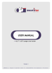
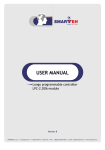
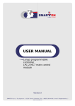
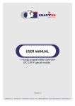
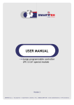
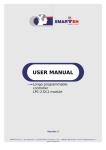
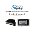
USER MANUAL
Longo programmable controller
LPC-2.MC8
Main Control module
Version 8
SMARTEH d.o.o. / Poljubinj 114 / 5220 Tolmin / Slovenia / Tel.: +386(0) 388 44 00 / e-mail: [email protected] / www.smarteh.si
Longo programmable controller LPC-2.MC8
Written by SMARTEH d.o.o.
Copyright © 2014, SMARTEH d.o.o.
User Manual
Document Version: 008
December, 2015
i
Longo programmable controller LPC-2.MC8
STANDARDS AND PROVISIONS: Standards, recommendations, regulations
and provisions of the country in which the devices will operate, must
be considered while planning and setting up electrical devices. Work
on 230 V AC network is allowed for authorized personnel only.
DANGER WARNINGS: Devices or modules must be protected from
moisture, dirt and damage during transport, storing and operation.
WARRANTY CONDITIONS: For all modules LONGO LPC-2 – if no
modifications are performed upon and are correctly connected by
authorized personnel – in consideration of maximum allowed
connecting power, we offer warranty for 24 months from date of sale
to end buyer. In case of claims within warranty time, which are based
on material malfunctions the producer offers free replacement. The
method of return of malfunctioned module, together with description,
can be arranged with our authorized representative. Warranty does
not include damage due to transport or because of unconsidered
corresponding regulations of the country, where the module is
installed.
This device must be connected properly by the provided connection
scheme in this manual. Misconnections may result in device damage,
fire or personal injury.
Hazardous voltage in the device can cause electric shock and may
result in personal injury or death.
NEVER SERVICE THIS PRODUCT YOURSELF!
This device must not be installed in the systems critical for life (e.g.
medical devices, aircrafts, etc.).
If the device is used in a manner not specified by the manufacturer,
the degree of protection provided by the equipment may be impaired.
Waste electrical and electronic equipment (WEEE) must be collected
separately!
LONGO LPC-2 complies to the following standards:
• EMC:EN 61000-6-2 (EN 50082), EN 61000-6-4 (EN 50081)
• LVD: IEC 61131-2
• Vibrations and climatic-mechanical: EN 60068-2-6, EN 60068-2-27,
EN 60068-2-29
Smarteh d.o.o. operates a policy of continuous development.
Therefore we reserve the right to make changes and improvements to
any of the products described in this manual without any prior notice.
MANUFACTURER:
SMARTEH d.o.o.
Poljubinj 114
5220 Tolmin
Slovenia
ii
Longo programmable controller LPC-2.MC8
Longo programmable controller LPC-2.MC8
1 DESCRIPTION...................................................................................1
2 FEATURES.......................................................................................2
3 OPERATION.....................................................................................3
4 INSTALLATION..................................................................................5
4.1 Connection scheme....................................................................5
4.2 Mounting instructions.................................................................7
4.3 Module labeling........................................................................8
5 TECHNICAL SPECIFICATIONS..................................................................9
6 CHANGES .....................................................................................10
7 NOTES..........................................................................................11
iii
Longo programmable controller LPC-2.MC8
1 DESCRIPTION
LPC-2.MC8 (Main Controll module) is an open programmable PLC controller.
On its sides, there are two extensions buses where various inputs, outputs, special and
communication modules can be attached. It has integrated USB programming port, port for
connection of intelligent peripheral modules and Ethernet Modbus port, for network connectivity.
Controller is powered from main power supply.
Controller is accompanied with Smarteh IDE application. It is a tool, where various modules can be
put together to a configuration, based on number and type of electrical signals needed. Smarteh IDE
takes care for proper modules position. After configuration is finished, select program at home
page, to write PLC application.
NOTE: For proper system configuration and data allocation please refer to Smarteh IDE software
help menu.
1
Longo programmable controller LPC-2.MC8
2 FEATURES
Figure 1: LPC-2.MC8 module.
Table 1: Technical data
Ethernet connectivity with Modbus TCP slave (server) functionality
USB port for Debugging, Application and Default parameters transfer
CAN ports
RS-485 connectivity for intelligent peripheral modules (thermostat, RFID, IR, operator terminal...)
Integrated RTC with Super Cap backup
32 kB non-volatile memory
4 kb Flash memory available for parameter storage
Mains power supplied
2
Longo programmable controller LPC-2.MC8
3 OPERATION
There are several logical units attached with this module. They can be accessed from Smarteh IDE
application. Some units are enabled by default, others can be enabled through Smarteh IDE. Unit is
enabled when any of its variables is used.
PLC has 32 kB of non-volatile memory, which is available to any variable used inside application,
simply by setting the variable Option to Retain.
PLC also provides 4 kB of ROM (flash) memory area to the user who would like to use some
initialization data or some fixed parameters. This area can be accessed from application only for
reading. Setting the values of variables in Flash can be issued with Flash uploader page.
In Flash memory area there are some preloaded data stored:
MAC: is unique for every unit produced. This value can be also found on the label attached
on the housing of the unit.
IP: default value is 192.168.19.223.
MASK: default value is 255.255.255.0
Gateway, Primary DNS, Secondary DNS: default 0.0.0.0
Flash memory unit
This unit enables only reading from its variables. Setting the variables is issued with one of Smarteh
IDE plugins, Flash uploader page.
Flash unit provides reading of a portion of a flash memory inside MC8 module. Flash memory is nonvolatile, therefor keeps data for ever.
Usually this area is used for setting some data to the default value, even before installation of the
unit to its position. After, when PLC is commissioned, the data are already present and there is no
need for further setting. This keeps its data in this area some startup parameters can be written.
RTC unit
For RTC back-up and for Retain variables there is Super Capacitor instead of battery integrated
inside
PLC.
This
way
replacement
of
the
discharged
battery
is
avoided.
The Retention time is minimum 30 days from the power down.
RTC time provides date and time information. Along, alarming function is also supported.
Modbus slave unit
ModbusTCP slave has 512 addresses in each memory section.
Coils:
Discrete Inputs:
Input Register:
Holding Registers:
00000
10000
30000
40000
to
to
to
to
00511
10511
30511
40511
Supports up to 3 connections to the slave unit.
Scan rate is 500 ms or greater.
3
Longo programmable controller LPC-2.MC8
CANopen unit
CANopen unit consists of Master and Slave communication ports. They are independent, thus can be
connected to two different CAN networks at the same time.
The ports can operate at baud rates 50 kbps, 125 kbps or 250 kbps.
It follows the internationally standardized (EN 50325-4) CAN-based higher-layer protocol for
embedded control systems. Advised rules and concepts by this standard must be followed to fulfill
the conditions and so achieving normal operation and results.
The structure of the network as cable type and lengths, baud rates, number of the nodes and
termination must be taken into account within the recommendations and requirements, when
designing the network.
The bus network can consist of at least one Master and at list one Slave node by the standard, but it
is advised that with increased number of nodes, the Master node fastest interval is extended. Below
are two examples:
Example1: network with 1 master and 9 slaves, every slave have defined 32 (4x8) byte of data and
baud rate 125 Kbps. Fastest Cycle time for this configuration is 50 ms.
Example2: network with 1 master and 4 slaves, every slave have defined 4 byte of data and baud
rate 250 Kbps. Fastest Cycle time for this configuration is 5 ms.
5 millisecond is the fastest recommended cycle time.
It is recommended to power-up all the nodes on the same network at the same time, if some or all
nodes had been reprogrammed (to reinitialize the communication properly).
Additional operational information
After the installation of the PLC it must be at least 20 minute enabled power supply, before the
internal battery is charged and the retain memory is ready to save variables without loosing them
switching power supply off.
RUN / STOP Switch
Run mode: Status (RUN) LED on indicate that the PLC program is up and user program is running.
Stop mode: When the switch is turn to STOP state, the status (RUN) LED is Off. The application
switch to the bootloader, this fact allow users to program LPC-2.MC8.
When the user is done programming the PLC via USB the switch must be turned ON and the MC8
starts the application.
PLC task cycle time
Main PLC task interval (under Project tab -> Resource → Tasks → Interval) time is not recommended
to be set lower than 50 ms.
4
Longo programmable controller LPC-2.MC8
4 INSTALLATION
4.1 Connection scheme
Figure 2: Connection scheme
Table 2: Power supply
PS.1(
)
PS.2 (N)
PS.3 (L)
Functional earthing
provides better EMI/EMC
Power supply
100 .. 250 V AC, 50/60 Hz
5
Longo programmable controller LPC-2.MC8
Table 3: CAN
CAN1.4
CAN Low
CAN1.5
CAN High
CAN.6
Reference point
CAN2.7
CAN Low
CAN2.8
CAN High
0 .. 5 V
0V
0 .. 5 V
Table 4: Switches
S1
Operation
mode
RUN: PLC normal operational mode
STOP: application not running, connected modules outputs in their off
state
RST: when moved from STOP to RUN mode, PLC is reset and application
starts from its beginning.
S2
CAN bus
termination
ON: corresponding channel is internally terminated with 120 ohm
OFF: no internal termination present
Table 5: LED
LED1
Application running
On: application is running
Off: application is stopped or PLC in boot mode
LED2
USB connectivity
On: USB connection established
Off: no USB connection
LED3
Power
On: module is powered ON
Off: module has no power supply
6
Longo programmable controller LPC-2.MC8
4.2 Mounting instructions
53
36
95
90
Figure 3: Housing dimensions
77
Dimensions in milimeters.
EXTERNAL SWITCH OR CIRCUIT-BREAKER AND EXTERNAL OVERCURRENT
PROTECTION: The unit is allowed to be connected to installation with over
current protection that has nominal value of 16 A or less.
RECOMMENDATION ON SWITCH OR CIRCUIT-BREAKER PROTECTION: There should
be two poles main switch in the installation in order to switch off the unit. The
switch should meet the requirements of standard IEC60947 and have a nominal
value at least 6 A. The switch or circuit-breaker should be within easy reach of
the operator. It should be marked as the disconnecting device for the equipment.
All connections, module attachments and assembling must be done while module
is not connected to the main power supply.
Wires connected to the module must have cross sectional area at least 0.75 mm 2.
Minimum temperature rating of wire insulation must be 85 °C
1. Switch OFF main power supply.
2. Mount module to the provided place inside an electrical panel (DIN EN50022-35 rail
mounting).
3. Mount other IO modules (if required). Mount each module to the DIN rail first, then attach
modules together through K1, K2 connectors.
4. Connect needed input, output and communication wires.
5. Switch ON main power supply.
Dismount in reverse order. For mounting/dismounting modules to/from DIN rail a free space of at
least one module must be left on the DIN rail.
7
Longo programmable controller LPC-2.MC8
4.3 Module labeling
Figure 5: Labels on housing
Label 1 (sample):
Label 2 (sample):
LPC-2.MC8
P/N:225MC813002001
D/C: 31/10
S/N: MC8-S9-1000000190
Label 1 descriptions:
1. LPC-2.MC8 is the full product name.
2. P/N:225MC8040001001 is the part number.
•
225 – general code for product family,
•
MC8 – short product name,
•
04001 – sequence code,
•
•
04 – year of code opening
•
001 – derivation code
001 – version code (reserved for future HW and/or SW firmware upgrades).
3. D/C:16/11 is the date code.
•
16 – week and
•
05 – year of production.
Label 2 descriptions:
1. S/N:MC8-S9-1100000190 is the serial number.
•
MC8 – short product name,
•
S9 – user code (test procedure, e.g. Smarteh person xxx),
•
1100000190 – year and current stack code,
•
11 – year (last two cyphers)
•
00000190 – current stack number; previous module would have the stack number
00000189 and the next one 00000191.
8
Longo programmable controller LPC-2.MC8
5 TECHNICAL SPECIFICATIONS
Table 6: Technical specifications
Power supply
100 .. 250 V AC, 50/60 Hz
Power consumption
Max. 35 W
Connection type
screw type connector for stranded wire 0.75 to 2.5 mm2
USB
B connector type, device mode,
Low speed, Full speed
RTC
capacitor backed up with retention cca. 30 days.
Dimensions (L x W x H)
90 x 53 x 60 mm
Weight
180 g
Ambient temperature
0 to 50°C
Ambient humidity
max. 95 %, no condensation
Maximum altitude
2000 m
Mounting position
vertical
Transport and storage temperature
-20 to 60 °C
Pollution degree
2
Over-voltage category
II
Electrical equipment
Class II (double insulation)
Protection class
IP 30
9
Longo programmable controller LPC-2.MC8
6 CHANGES
The following table describes all the changes to the document.
Date
V.
Description
17.12.2015
008
LPC Manager → Smarteh IDE.
01.09.2015
007
Technical data update.
01.06.2014
006
Technical data update. CANOpen Unit section added.
01.05.2013
005
Technical data update. Modbus section added.
01.02.2013
004
Technical data update.
01.07.2013
003
Technical data update.
01.11.2011
002
Technical data update.
23.09.2011
001
The initial version, issued as LPC-2.MC8 UserManual.
10
Longo programmable controller LPC-2.MC8
7 NOTES
11