1
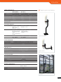
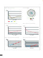
RF SAFETY CATALOG EMF MEASUREMENT AND MONITORING TOOLS Quick Guide of MVG's RF Safety Solutions System name EME Guard XS Product range Worker Safety Worker Safety Worker / Public Safety Public Safety Public Safety • Accurate measurement with Tri-axis isotropic sensor •A ccurate measurement with Tri-axis isotropic sensor • Real time transmission of the measurement • Frequency selective portable system • Frequency selective system for in-situ spot measurement • Preset Alarm threshold •U ser definable alarm thresholds • Affordable solution •D ata storage Software • Cover frequencies of all cellular networks including short pulsed signals Key feature EME Guard FlashRad • Broadband sensor • Dedicated software for FlashRad network management • Independent measurement on Uplink and Downlink for cellular network bands INSITE Free • Compatible with most spectrum analyzers available on the market • Real time monitoring on PC or Smartphone (Android Application) • Fully automatic measurement process Utilisation mode Portable Portable Stationary Portable Portable Selectivity Broadband Broadband Broadband Selectivity per services Selectivity per channel 80 MHz to 6 GHz 27 MHz to 40 GHz robe dependent: P • 900 MHz to 11 GHz • 700 MHz to 6 GHz • 700 MHz to 3 GHz 20 selected frequency bands from 88 MHz to 5850 MHz 100 KHz to 6 GHz Frequency bands • • • Audio alarm Visual alarm Monitoring • • • • Data storage Software Industries/ Users • • • • Page • • • NA EME Guard Analysis FlashRad software EME Spy Analysis INSITE Free software • Antenna installer & maintenance companies •A ntenna installer & maintenance companies • Military/Defense • Local and national authorities • Certification agencies • Operators (cellular network, broadcast, PMR, radar, …) •O perators (cellular network, broadcast, PMR, radar, …) • Telecom Regulators • Research agencies, R&D labs, universities • Operators (cellular, network, broadcast, PMR, radar, …) • Military/Defense •M ilitary/Defense • RF laboratory workers •R F laboratory workers • Operators (cellular network, broadcast, PMR, radar, …) • RF laboratory workers • Research agencies, R&D labs, universities • Real estate pre certification • Military/Defense P 13 P 18 P 21 • Telecom Regulators • RF laboratory • Local and national authorities • Local and national authorities 2 EME Spy 200 P8 P 10 © MVG 2015 Product specifications and descriptions in this catalog are subject to change without notice. Actual products may differ in appearance from images shown. • Telecom Regulators The Smart Choice for RF Safety Since its creation in 1986, Microwave Vision Group (MVG) has developed a unique expertise in the visualization of electromagnetic waves. The Group's mission is to extend this unique technology to all sectors where it will bring strong added value. Year after year, the Group develops a complete range of Radio Frequency (RF) instruments to measure the level of exposure to the electromagnetic field and to address the following needs: • To continuously record the electromagnetic field level and alerts the user to potential overexposure • To monitor actual levels and compare them to the regulatory limits • To address public concern through appropriate communication • To simulate EMF radiation in real environments 3 Why do we measure exposure levels? Electromagnetic fields are increasingly present in our living environment. For this reason they arouse ever more concern and raise questions about the possible harmful effects of these fields on health. As part of its public heath charter and in response to growing concerns, the World Health Organization (WHO) introduced the International Electromagnetic Fields Project in 1996. This Project aims to assess the health and environmental effects caused by static or variable electric and magnetic fields in frequencies from 0 to 300 GHz. Wherever there is electricity (voltage or current), there is electromagnetic field (EMF). All types of wireless transmissions (radio/TV broadcasting, voice/data wireless communication) use electromagnetic fields. The generated field propagates in the form of waves and is all around us even if we cannot see it or hear it. The electromagnetic field has two components: the Electric E Field and Magnetic H Field, and they are proportional to each other in far field measurement. Wave length E Z H ICNIRP - Reference levels for exposure to electric fields Field (V/m) [logarithmic scale] 1000 137 100 61 28 10 10 100 1000 Frequency (MHz) [logarithmic scale] Occupational 4 General public 10000 BASIC RESTRICTIONS AND REFERENCE LEVELS To protect individuals from the potential health effects of radio waves, protection levels known as basic restrictions were recommended by the International Commission on Non-Ionizing Radiation Protection (ICNIRP - http://www. icnirp.org). The ICNIRP is the non-governmental organization officially recognized by the WHO and the International Labor Organization (ILO) in the field of Non-Ionizing Radiation. These basic restrictions were established based on published biomedical studies and relative to the health effects of electromagnetic waves. In the area of high frequencies, they are expressed in terms of Specific Absorption Rate (SAR) and the biological effects appear above 4 Watts per kilogram for the entire body (increase in body temperature of more than one degree) and above 100 watts per kilogram locally. The basic restrictions are set so as to take into account uncertainties related to personal sensitivity, environmental conditions and diversity in the age and state of health of the populations concerned. The protection levels for workers were established at one tenth of these exposure levels producing an impact, and fifty times lower for the general public. For the general public, the basic restrictions thus require that the power absorbed per kilogram (SAR) be at 0.08 W/kg maximum for the entire body and 2 W/kg maximum for 10 grams of tissue. Given the complexity of measuring the SAR in situ, the ICNIRP (based on the studies carried out to find the relation between a plane wave power surface density and the power absorbed by an ellipsoid representing a human body) has defined reference levels deduced from basic restrictions and expressed in Volts per meter or Watts per square meter. Compliance with all the recommended reference levels will ensure that the basic restrictions are observed. If the measured values are higher than the reference levels, this does not necessarily mean that the basic restrictions have been exceeded. In this case, check whether these levels of exposure are lower than the basic restrictions. REGULATION LINKED TO THE EXPOSURE LEVELS MEASUREMENT PROTOCOLS AND STANDARDS In Europe, the exposure limits follow the European Union Council Recommendation 1999/519/CE of July 12th 1999 regarding the public exposure to electromagnetic fields. The exposure limit values are revised periodically if needed. The last report from the Scientific Committee on Emerging and Newly Identified Health Risks (SCENIHR), an independent European Commission body, on the health effects of electromagnetic fields, came out in January 2009. The conclusions of this report do not challenge the exposure limit values proposed by the above-mentioned European recommendation. In order to compare the exposure levels measured at the established limits, measuring protocols have been established by the main standardization bodies. Some examples are the ECC/REC/(02)04 recommendation and the EN50383, EN50413, EN50492, EN62311 standards in Europe and the IEEE Std.C95.3 standard in North America. The great majority of European Union member countries follow this recommendation either by incorporating it into national regulations (Austria, Czech Republic, Estonia, Finland, France, Germany, Hungary, Portugal, Romania, Slovakia, Spain) or in the form of recommendations (Denmark, Ireland, Latvia, Malta, Netherlands, Sweden, United Kingdom). However, different approaches are applied in certain member states with the introduction of more restrictive limits in "living areas" (Belgium, Bulgaria, Greece, Italy, Lithuania, Luxembourg, Poland, Slovenia). The same goes for Switzerland and Liechtenstein. The values chosen by these States are based on the application of the principle of precaution related to potential health risks related to exposure to electromagnetic fields and the exposure limit values were in most cases set in an arbitrary manner. Concerning workers, as part of the European directive on exposure of workers to the risks arising from electromagnetic fields (directive 2013/35/EU of 26 June 2013), all employers must now determine the exposure (levels, duration), assess risks and take the necessary measures to ensure safety and protect the health of workers from the risks arising from professional exposure to these electromagnetic fields. In particular, they must: • measure and/or calculate the electromagnetic field levels to which workers are exposed, via the appropriate departments at regular intervals • record the results of this assessment on a reliable medium that can be consulted subsequently Other information concerning the regulation throughout the world may be found directly on the WHO website: http:// www.who.int/docstore/peh-emf/EMFStandards/who-0102/ Worldmap5.htm. WHY MEASURE ELECTROMAGNETIC FIELDS? Measuring the electromagnetic field is essential to check that exposure levels respect the regulatory limits established in each country, and thus ensure the safety of individuals exposed, whether members of the general public or workers. For individuals who work in proximity to high frequency emmiters, the measurement ensures that the emitter is switched off when the intervention takes place and/or that the electromagnetic fields are well below the recommended levels. It thus reassures these individuals who can then complete their work without worry. The introduction of a Monitoring network on the work site allows this exposure to be constantly monitored. In either case, the measurement allows the employer to check that employees have not been over-exposed during their assignments. Unlike a simulation or calculation, a measurement is concrete. Communicating the measured exposure levels, which are mostly very low as compared to the reference levels, provides reassurance for the concerned public. If the measurement reveals high levels of exposure, it then allows remedial actions to be implemented. Here again, the measurement can be occasional in time and space: an exposure meter can be lent to an administration official, who for a given period can check the levels to which he/she is exposed in the home or workplace, or it can be performed via a Monitoring network, with each probe sending these measurements over time to a database or eventually to a website, which can then be used by the authoroties (muincipality for example) to communicate the overall exposure of a city to the public. The measurement taken by scientists by lending an exposure meter to a representative panel also allows us to find out the average exposure for a given population, and potentially the change in this exposure according to the technology (television broadcast, 2G, 3G, 4G mobile communications, domestic networks). 5 Finally, the measurements can be used to confirm and/or calibrate a propagation model. An appropriate combination of simulation and measurement allows us to obtain a precise mapping of exposure in a large geographic area, and to monitor changes to this exposure over time, in quasi-real time mode. of three elementary antennae (dipole or monopole) appropriately placed with respect to each other. HOW TO MEASURE EXPOSURE TO ELECTROMAGNETIC FIELDS Sensitivity: The sensitivity of an electromagnetic field measurement probe or system is the minimum level of the field that can be measured with this tool. Exposure to electromagnetic fields is generally measured using a probe and a receiver (Volt meter or power meter). An electromagnetic field probe is an "antenna" that has been optimized to measure exposure to electromagnetic fields. Dynamic: The dynamic of an electromagnetic field measurement probe or system is the difference between the maximum and minimum field that can be measured with this tool. It is generally expressed in dB. There are two types of probe for measuring exposure to electromagnetic fields: "broadband" probes and "frequency selective" probes. Frequency flatness: This parameter characterizes the quality of a broadband probe. It represents the variations of the measured E-field at a fixed frequency, when the level of the E-field is varied over the dynamic range of the probe. A broadband probe generally comprises a dipole and a diode connected directly between the two poles of the antenna. Using this type of probe, the voltage proportional to the field level is measured. The quality of this type of probe will therefore depend on its ability to provide the same voltage for the same field and regardless of the frequency (frequency is of course within the usage bandwidth) of the field to be measured. These "broadband" probes provide information on the level of exposure, but do not indicate the frequency of the field to which the user is exposed. They are mostly used in warning products (worker exposure meter) or for a quick measurement of compliance when measured levels remain low. This type of probe is defined by its isotropy, its bandwidth, its sensitivity, its measurement dynamic, its frequency flatness and its linearity. The second type of probe, depending on the recevier topology used with it, provides information regarding the frequency and the amplitude of the measured field, as well as information on the level. They are incorporated into more refined compliance or information measuring products. They are defined by their isotropy, their bandwidth, and their antenna gain or factor: the dynamic, sensitivity and linearity in this case are dependent on the receiver topology used with a given probe. Isotropy: The isotropy characterizes the ability of the field measuring probe to always provide the same response to a given field level, regardless of the direction of arrival of this field or its polarizations. It is a parameter required by most of the current measurement standards. There is no single naturally isotropic antenna: for electromagnetic field probes, this isotropy is thus obtained by combining the radiation pattern 6 Bandwidth: The performances of an electromagnetic field measurement probe vary according to the frequency of the field to be measured. They are thus defined to be used over a limited frequency range, known as the usage bandwidth. Linearity: This parameter characterizes the quality of a broadband probe. It represents the variations in the levels measured, with fixed frequency and making the level of the field measured over the probe's measuring range vary. Antenna Gain and/or Factor: An antenna gain (respectively of an electromagnetic field measuring probe) characterizes its ability to emit (respectively receive) in a specified direction. It is generally expressed in dBi, taking as a reference an isotropic antenna, meaning a fictitious antenna that radiates uniformly in all directions. The gain of this antenna is thus 1, or 0 dBi (dBi for decibel-isotropic). The role of an electromagnetic field probe is to transform the recieved electromagnetic field level into RF power. The antenna factor is defined as the ratio of the electromagnetic field captured by this antenna to the voltage measured at the antenna terminals. AF = E Vr The antenna factor (expressed in dB) is linked to its gain by the following equation: AF = 20 Log(F) − G − 29,78 In this equation, F is the frequency in MHz, and G is the gain in dBi. The power received by an antenna capturing an electromagnetic field can easily be found using the following formula: Pr = 20 * Log(E) − AF + 13 In this equation, Pr is expressed in dBm, E in V/m and the antenna factor in dB. Worker Safety 7 EME Guard XS + •Accurate measurement with tri-axis sensors •Instant audio and visual alarm •Robust, reliable and user-friendly Main features Product Configuration User profile Equipment •Persons working near antennas including installation and maintenance workers, broadcast, PMR and mobile phone operators or regulatory body employees ■ ■ ■ ■ ■ ■ ■ ■ Measurement capabilities •Continuous monitoring of Electromagnetic Field levels with isotropic tri-axis E-field sensors •EMF Level indicated by a LED color scale •Audio and visual alarms triggered when EMF exceeds the reference level EME Guard XS MVG Case Wirst strap Lanyard Connecting adapter Armband 2 x 1.5 V Size N Alkaline batteries Instructions for use Services ■ Initial calibration Frequency bands •80 MHz – 6 GHz Additional calibration Extended warranty Safety recommendations • ICNIRP • FCC 96-326 •Safety Code 6 •2013/35/UE •Alarm threshold can be adjusted at MVG factory upon request New EU Directive Included 8 Optional I EME Guard XS TECHNICAL CHARACTERISTICS Probe Isotropic 3-axes probe Frequency range 80 MHz - 6 GHz Lower detection limit 5 V/m Upper detection limit 350 V/m MEASUREMENT UNCERTAINTY Frequency (MHz) Frequency response Axial isotropy 80 - 700 -2 / +4 dB +/- 0.5 dB 700 - 2700 -1 / +5 dB +/- 0.7 dB 2700 - 6000 +2 / +7 dB +/- 0.9 dB ALARM & CONFIGURATION Reference threshold Alarm threshold can be adjusted at MVG factory upon request Visual alarm 7 LEDs Audio alarm 2 tones (activated from 5 to 350 V/m) Low battery indicator Orange flashing LED MEASUREMENT CONFIGURATION Measurement period 1 sec CONDITIONS FOR USE Temperature, humidity -10°C to 50°C, 85% max humidity Battery 2 x 1.5 V Size N Alkaline removable batteries Battery life > 1000 hours (> 50 days)(1) MECHANICAL CHARACTERISTICS Dimensions132.5 x 48.5 x 28.7 mm (LxWxH) without connecting adapter Weight 120 g with batteries (1) If no alarm is triggered 9 EME Guard + Main features System Configuration User profile Software • Anyone working close to emitting antennas (broadcast, base station, radars …) • Installation and maintenance staff, broadcast, PMR and mobile phone operators or regulatory bodies employees ■ EME Guard Analysis Measurement capabilities •Continuously records the electromagnetic field level and alerts user to potential over-exposure Equipment ■ ■ ■ ■ Case Belt clip USB cable Battery charger Accessories Holster Frequency bands •27 MHz to 40 GHz Services Related recommendations ■ Calibration report ■ Initial calibration • FCC 96-326 • ICNIRP • Safety Code 6 • 2013/35/UE • Exposure thresholds are user-definable and can be adapted to any recommendation Additional calibration Training Extended warranty New EU Directive 10 • Accurate measurement with triaxial isotropic probe • Customization of alarm thresholds • Data storage software • Robust, all weather design Included Optional I EME Guard A user friendly and flexible instrument The EME Guard Analysis software defines two user profiles: STEP 3: Define the recording period. STEP 4: Start the device (ON/OFF button) and perform measurements. STEP 5: Import the measurements in the form of secure files using a USB cable and display the results. ➊Administrator mode, gives additional rights to configure the device to requirements (threshold definition). ➋ User mode, enables download and visualization of measurements recorded in the embedded memory of the device. The Administrator can customize the device according to the thresholds defined by his own guidelines. > Only the Administrator is given right of access to device configuration and customize. STEP 1: Define the reference threshold that will trigger the visual alarm. The 4 warning lights are activated as soon as exposure level attains 25%, 50%, 75% and 100% of the chosen reference threshold. STEP 2: Define the thresholds that will trigger the audio and vibrating alarms: Over a 6 minute mean: the alarm is triggered as soon as the mean calculated over the preceding 6 minutes exceeds the predetermined threshold. This 6 minute calculation is the reference duration which conforms to the ICNIRP recommendations. Or: Instantaneous: as soon as a measurement exceeds the threshold, the alarms are triggered. The measurement files are downloaded on the PC’s hard disc as binary files, thus ensuring the safety of historical data. High performance probe for accurate measurements The EME Guard is equipped with a triaxial probe which guarantees measurement isotropy. Each device comes with a calibration report. The performance of this sensor has been optimized to ensure maximum isotropy. Isotropy at 1400 MHz Isotropy at 2100 MHz Alarm front view 11 A robust product The device is equipped with an auto-test system which is launched when the device is switched on. This test ensures that the EME Guard is functioning normally and that battery level is sufficient. In any case, if the battery level is too low, an orange warning light alerts the user immediately. The case is metallic and ensures an IP55 Ingress Protection level, ideal for outdoor use. TECHNICAL CHARACTERISTICS CONDITIONS FOR USE Frequency range 27 MHz – 40 GHz Temperature, humidity Upper detection limit 200 V/m Power supply of battery charger 110 - 240 VAC, 50 - 60 Hz Lower detection limit 5 V/m Battery Lithium-Ion Damage Level (CW) : > 4000 V/m (> 29 dB above standard) Battery life > 100 hours Type of link USB -10 to 50°C, 85% max. humidity MEASUREMENT UNCERTAINTY Axial isotropy +/- 1 dB at 1400 MHz +/- 2 dB at 2100 MHz Frequency response 27 MHz - 2.5 GHz : +/- 3 dB 2.5 GHz - 6 GHz : + 6/0 dB 6 GHz - 10 GHz : + 12/+ 6 dB 10 GHz - 20 GHz : + 10/0 dB 20 GHz - 40 GHz : + 8/- 3 dB MECHANICAL CHARACTERISTICS Dimensions 172 x 60 x 35 mm (H, L, W) without belt clip Weight 320 g Protection IP 55 HARDWARE REQUIREMENTS ALARM & CONFIGURATION PC Pentium 500 MHz or equivalent Reference threshold Configurable by the user 20, 40, 60, 80, 100 or 140 V/m Cable link USB Operating system XP / WIN7 / WIN8 Alarm mode Instantaneous or 6 min. mean Memory 256 MB RAM Visual alarm 4 LEDs 25%, 50%, 75% and 100% of the reference threshold Free space on hard disk 100 MB Audio alarm Activated (from 5 V/m to 137 V/m) or de-activated Vibrator Activated (from 5 V/m to 137 V/m) or de-activated Low battery indicator Orange LED MEASUREMENT CONFIGURATION 12 Processor Update period for display and alarms 1 sec Measurement recording Activated or de-activated Recording capacity 30 000 measurements MAX Recording period 1-255 sec Duration of recording • min. • max. 1 mn Duration in mn = 30 000 points X recording period (sec) 60 FlashRad + •Alert users with sound and light •Cover frequencies of all cellular networks including short pulsed signals NEW •Monitor low EMF levels in public areas Product Configuration Main features User profile Software • Companies situated near antennas or radar transmitters, who wish to protect their employees from questionable EMF levels (military bases, airports, etc.) ■ FlashRad software on CD Rom Measurement capabilities • Continuous measurement of EMF levels. Each monitor detects signals and then transmits the data to the surveillance PC to be processed individually • Data is collected separately from each monitor in place Frequency bands • 900 MHz – 11 GHz; higher or lower frequencies possible Safety recommendations Equipment ■ External connectors (mounted on cable or not) ■ Ground or wall support Accessories ■ Case LEDs box with alarm + USB cable Services ■ Initial calibration ■ Calibration report Ground or wall installation Training Additional calibration Extended warranty • EMF exposure limits can be defined by users and adjusted to any regulation or recommendation Included Optional 13 FlashRad is a safety wideband exposure monitoring system that performs continuous measurements of electromagnetic field (EMF) levels. It detects all kinds of pulsed signals, including short pulsed radar, emitted from various sources outside a building. When predetermined EMF levels are exceeded, the FlashRads monitor sounds and flashes a warning in its immediate surroundings while sending a signal to the surveillance PC for action. Overview of FlashRad systems network Antenna Ethernet network LEDs Box (alarms) optional Surveillance PC USB Link FlashRads are connected to a PC via Ethernet. Continuous EMF level measurements are sent to the PC where the FlashRad monitoring system software collects and displays the incoming data. If the FlashRads detect excessive RF levels, a signal is sent to the PC indicating which monitor is detecting the overexposed area. The technician can then take action. Note that each monitor can be stopped or started as necessary. 14 The PC will send a signal to trigger the alarms in the FlashRads when the EMF levels exceed the predetermined levels. A LED light box is available as an option to allow monitoring in multiple areas. It is connected to the PC by a USB cable of up to 10 meters. I FlashRad TECHNICAL CHARACTERISTICS HIGH LEVEL PULSED SIGNALS (RADAR...) WORKERS AREA (BTS, TEST...) PUBLIC AREA Probe reference FR100 FR200 FR300 Probe Isotropic 3-axes probe Isotropic 3-axes probe Isotropic 3-axes probe Frequency range 900 MHz – 11 GHz 700 MHz – 6 GHz 700 MHz – 3 GHz Lower detection limit 50 V/m 10 V/m 0.5 V/m Upper detection limit 1000 V/m 200 V/m TBD Destruction limit > 1500 V/m > 300 V/m TBD Minimum pulse width measurement ≥ 1 µs ≥ 50 µs TBD 700 MHz – 6 GHz (@50 V/m) : +/-1 dB TBD Mechanical installation MEASUREMENT UNCERTAINTY Axial isotropy 900 MHz – 6 GHz (@150 V/m) : +/-1 dB 6 GHz – 11 GHz (@150 V/m) : +/-2.2 dB Frequency response 900 MHz – 1 GHz 700 MHz – 2 GHz (@150 V/m) : +3.8/-1.2 dB(@50 V/m) : +/-3 dB 1 GHz – 8 GHz (@150 V/m) : 2 GHz – 6 GHz (@50 V/m) : +/-2 dB +3/+1 dB 8 GHz – 11 GHz (@150 V/m) : +5/+3 dB TBD Linearity +/-0.5 dB (200 – 1000 V/m) TBD +/-1 dB (20 – 200 V/m) Ground Installation ALARM & CONFIGURATION Alarms Audio & visual Reference threshold Configurable from lower until upper detection limits of the probe Measurement records On PC Measurement interval 1-60 sec CONDITIONS FOR USE Temperature, humidity Power supply Type of network connection -15°C - 50°C, 95% max humidity 90 – 264 VAC, 47 – 440 Hz Ethernet Wall installation SOFTWARE REQUIREMENTS Processor Network connection Operating system Memory Free space on hard disk PC Pentium 500 MHz or equivalent Ethernet Windows XP 7/8 256 MB RAM 100 MB MECHANICAL CHARACTERISTICS Dimensions Height = 570 mm Diameter = 100 mm Weight 3.6 kg Protection IP 55 FlashRad 15 16 Public Safety EME Spy 200 + Watch a success story of EME Spy 140 Main features Product Configuration User profile Equipment •Municipalities, governmental agencies, regulatory bodies, research laboratories, universities, broadcast, PMR, and mobile phone operators ■ ■ ■ ■ ■ ■ Measurement capabilities •Continuous monitoring of personal exposure to electromagnetic fields and identification of the contributors Frequency bands •20 selected frequency bands from 88 MHz – 5850 MHz Safety recommendations •Measurements can be compared with the reference levels advised by ICNIRP •LTE 800 MHz / 2600 MHz frequency bands included • Independent measurement on Uplink and Downlink for cellular network bands • Real time monitoring on PC (USB) or Smartphone (Bluetooth) • Android Application now available EME Spy analysis software User manual USB cable 4 rechargeable batteries Battery charger Case Real time visualisation kit Services ■ Initial calibration ■ Calibration report Installation Training Additional calibration Extended warranty Real time visualization kit (optional) •The field level for each frequency band is displayed as it is measured •Exports data to the EME Spy Analysis software for post processing and backup 18 Included Optional I EME Spy 200 TECHNICAL CHARACTERISTICS PROBE CHARACTERISTICS FREQUENCY RANGES Frequency MIN (MHz) Frequency MAX (MHz) Probe Tri-axial E-field probe 80 MHz – 6 GHz Sensitivity FM 87107 • FM, TV3, TETRA, TV4 & 5, WiFi 5G = 0,01 V/m • LTE 800, GSM, DCS, DECT, UMTS, WiFi 2G, LTE 2600, WiMax = 0,005 V/m TV3 174223 TETRA I 380 400 Dynamic 61.6 dB (up to 6 V/m) TETRA II 410 430 TETRA III 450 470 (1) Uplink: Sending of information from the mobile station to the BTS (2) Downlink: Sending of information from the BTS to the mobile station TV4&5 470770 LTE 800 (DL) 791 821 LTE 800 (UL) 832 862 MEASUREMENT CONFIGURATION GSM + UMTS 900 (UL) 880 915 Number of data points 80 000 max GSM + UMTS 900 (DL) 925 960 GSM 1800 (UL) 1710 1785 GSM 1800 (DL) 1805 1880 Logging intervals • From 1 to 4 bands: 2 - 255 s • From 5 to 10 bands: 3 - 255 s • From 11 to 20 bands: 4 - 255 s DECT 18801900 UMTS 2100 (UL) 1920 1980 UMTS 2100 (DL) 2110 2170 WiFi 2G 2400 2483.5 LTE 2600 (UL) 2500 2570 LTE 2600 (DL) 2620 2690 WiMax 33003900 WiFi 5G 5150 5850 3,0 2,5 2,0 1,5 1,0 (2) Differentiating uplink(1) and downlink is 0,5 not only useful to assess the contribution 0,0 of each transmitter, but also to avoid discrepancy in the results by phones emitting close to the dosimeter. EME Spy Analysis main window OPERATING CONDITIONS 3,0 2,5 2,0 1,5 1,0 0,5 0,0 3,0 2,5 2,0 1,5 1,0 0,5 0,0 Temperature, humidity -10 to 50°C, 85% of humidity Battery life* Recording mode: > 15 hours with a recording period of 10 sec > 6 hours with a recording period of 4 sec BlueTooth mode: > 10 hours of recording * 2 rechargeable batteries MECHANICAL CHARACTERISTICS Vertical Polarization Horizontal Polarization Dimensions 168.5 x 79 x 49.7 mm (H x L x W) Weight 440 g Protection IP 55 3,0 2,5 2,0 1,5 HARDWARE REQUIREMENTS Processor PC Pentium 500 MHz 0,5 Cable link USB Port 0,0 Operating system XP / WIN7 / WIN8 Free space on hard disc 200 MB 1,0 19 EME Spy 200 Real Time Kit A streamlined and ergonomic screen allows the visualization of only the most useful information in real time on a small laptop PC, tablet or smartphone via a ferrite USB cable (for Windows) or BlueTooth (for Android) ON WINDOWS PC OR TABLET ON ANDROID SMARTPHONE OR TABLET Real-time visualization of results via BlueTooth. Real-time visualization of results via USB. EME Spy Android Application NEW http://tinyurl.com/k268zrh Viewing real-time measurements of electromagnetic field of the EME Spy. View this at Google Earth*! Measurements of EME Spy are transmitted by a Bluetooth link to an Android smartphone to display the exposure levels generated by the main radio services (FM, TV, Cellular Networks, Wifi ...). BASIC MODE PRO MODE X X Backup + post-processing of measurements for compatibility with the EME Spy Analysis software X Geo-location of the measurements with GPS position X Generation of *.kmz files for compatibility with Google Earth X Real-time display The EME Spy Android APP is certified for Smartphones below: - Galaxy S series (Samsung) - Xperia Neo (Sony Ericsson) - Slim Cink (Wiko) - XT925 (Motorola) 20 Geolocalized measurements in Paris * Google Earth installation required. Visit our website for more information. Real-time Visualization Google Map View INSITE Free + • Compatible with most spectrum analyzers available on the market • Tri-axial probes with excellent isotropic measurement • Compatible with WIN7/WIN8 • Additional option for ANFR V3 protocols Main features System Configuration Measurement capabilities Software • Performs in situ spot measurements ■ INSITE Free on CD Rom with dongle key User profile •Regulation agencies, certification offices, municipalities, broadcast, PMR and mobile phone operators, installers, research laboratories, administrative bodies and more Frequency bands INSITE Free/ANFR on CD Rom with dongle key Equipment ■ 100 KHz to 3 GHz probe 700 MHz to 6 GHz probe Spectrum analyzer ■ Switch box (with battery charger) ■ Probe holder Wooden tripod •100 KHz to 6 GHz Related recommendations Accessories •ECC/REC/(02)04, EN50383 and EN 50492 ■ Cables Compatible with most spectrum analyzers Services • ANRITSU: MT8212B, • Rohde & Schwarz: MT8220A, MT8222A, FSH3/6, FSH4/8, ZVL3, MS2711A/D, MS2661B, FSHP, FSV3, FSL6 MS2721B, MS2665C, • AGILENT: E7495B, ESA MS2724B, MS2713E, series, 856xEC series, S332D, S362E N9912A • WILLTEK: 9101/9102 • BIRD: Signal Hawk ■ Initial probe and cable calibration Additional calibration Training Extended warranty Included Optional Required 21 INSITE Free is composed of a probe connected to a switch/amplification box. The system also requires a spectrum analyzer. These elements can be operated either manually or remotely through INSITE Free software. The software enables the user to define measurement scenarios, analyze measurements, review the results graphically and automatically generate reports in Excel format. The switch enables successive selections of the three measurement axes to obtain an isotropic result without changing the position of the probe. Equipped with an amplifier, the switch also improves the sensitivity of the system over the 100 KHz to 30 MHz frequency bands. RF link Switch Spectrum analyzer Probe Computer Description of the measurement chain with a 6 GHz measurement probe Measurement scenarios can be defined by the user to fit specific requirements ➊ INSITE Free SW is a flexible tool that can be configured by the user to perform measurements and generate reports according to specific measurement protocols, in particular those recommended by ECC. ➋ In addition, for the French market, INSITE Free/ ANFR SW follows the protocol v3 of the French National Agency of Frequencies (ANFR) step by step. STEP 1: Choose hardware configuration In this first phase, the user programs the measurement session according to his own hardware configuration: spectrum analyzer, GPS, probe, cable, UMTS scanner and 22 switch. For this purpose, the probes, cable and switch calibration files are selected and loaded. A selection of several probes is possible. INSITE Free works with all of the most frequently used spectrum analyzers. TEP 2: Define measurement scenario S Once the hardware has been configured, the user can program the measurement scenarios: • Choose frequency bands to be measured from a list or create user-defined bands • Define the channels or specific carriers • Define channel width • Choose attenuation mode • Choose analysis mode (peaks, TDMA or W-CDMA) • Choose automatic or manual definition of RBW/VBW I INSITE Free STEP 4: Visualize results The results can be visualized with the following functions: • Full scan or per frequency band • Zoom in with peak identification threshold • 3 types of scales for a better high and low band visualization • Quick view of element’s properties Sessions are saved in XML and results can be exported to Excel. The results can be compared to the reference levels given by specific guidelines. Two guidelines are available by default: • ICNIRP • Safety Code 6 (Other reference levels can be added upon request). Selection of BCCH for TDMA Analysis STEP 3: Perform measurement analysis. The data collected for each band is presented on the main window of the software. Measurements corresponding to each of the three axes can be displayed in order to check the polarisation of the electric field. Depending on the characteristics of the spectrum analyzer, the user can repeat the following analysis modes: • CW Analysis: selection of peaks according to predefined threshold • TDMA analysis: extrapolation of BCCH value • W-CDMA analysis: UMTS decoding (measurement and extrapolation of the CPICH value) The user can re-launch measurements using specific detection modes (positive peak, negative peak, sample…) and measurement modes (Max. hold, Min. hold, and average) available with the spectrum analyzer. High performance isotropic probes to cover the 100 KHz to 6 GHz frequency ranges Two probes are available: from 100 KHz to 3 GHz and from 700 MHz to 6 GHz. Both probes are made of three orthogonal monopoles. The patented shape of each monopole optimizes the functioning and isotropy of the probe over the entire frequency range. MECHANICAL CHARACTERISTICS / 100 KHz - 3 GHz PROBE Dimension (without cable) 406 mm Weight 980 gr RF cable length 2m Connector3N Protection IP 44 Conditions for use (temperature, humidity) -10 to 50°c, 85 % humidity ELECTRICAL CHARACTERISTICS / 100 KHz - 3 GHz PROBE TDMA Analysis CW Analysis Sensitivity at 900 MHz (Given for a spectrum analyzer sensitivity of -90 dBm) (Cable loss taken into account) 1 mV/m Max. E-field/900 MHz 200 V/m Isotropy at 900 MHz ± 1 dB Isotropy at 1800 MHz ± 1,7 dB W-CDMA Analysis 23 24 100 KHz - 3 GHz probe antenna factor Axial Isotropy at 900 MHz 100 KHz - 3 GHz probe sensitivity without amplifier 100 KHz - 30 MHz probe sensitivity with amplifier 100 KHz - 3 GHz Axial Isotropy with horizontal polarization 100 KHz - 3 GHz Axial Isotropy with vertical polarization I INSITE Free E (mV/m) 10 MECHANICAL CHARACTERISTICS / 700 MHz - 6 GHz PROBE ELECTRICAL CHARACTERISTICS / 700 MHz - 6 GHz PROBE Dimension (without cable) 8 70 mm 800 gr Sensitivity at 900 MHz (Given for a spectrum analyzer sensitivity of -90 dBm) (Cable loss taken into account) 3,5 mV/m Weight Max. E-field/900 MHz 200 V/m Isotropy at 900 MHz +/- 1,6 dB Isotropy at 1800 MHz +/- 2,5 dB 6 RF cable length 2m Connector3N 4 Protection IP 44 2 Conditions for use (temperature, humidity) 10 to 50°c, 85 % humidity 0 700 1700 2700 3700 4700 5700 Frequency (MHz) Axial Isotropy 3.6 GHz 700 MHz - 6 GHz probe antenna factor AF (dB) 90 deg 70 3.00 0.00 -3.00 -6.00 60 -9.00 180 deg 50 -12.00 90 deg -15.00 3.00 -18.00 0.00 -3.00 0 deg -6.00 -9.00 40 700 180 deg 1200 1700 0 deg 2200 2700 3200 3700 4200 4700 5200 5700 270 deg Frequency (MHz) F1 -12.00 -15.00 -18.00 F2 F3 270 deg 90 deg 3.00 700 MHz - 6 GHz probe sensitivity Axial Isotropy 5.6 GHz 0.00 -3.00 -6.00 -9.00 E (mV/m) 180 deg 10 -12.00 90 deg -15.00 3.00 -18.00 0.00 -3.00 0 deg -6.00 8 -9.00 6 180 deg 4 -12.00 -15.00 -18.00 0 deg 270 deg 2 PV PH 0 V/m 700 1700 2700 3700 4700 5700 270 deg Frequency (MHz) PV PH V/m AF (dB) 70 60 50 40 700 1200 1700 2200 2700 3200 3700 4200 4700 5200 5700 Frequency (MHz) F1 F2 F3 25 Perform isotropic measurements without changing the position of the probe INSITE Free System performs a measurement for each axis and all predefined bands. The power value measured on each axis is then converted into field value. FOR EACH BAND One scan for each axis X Conversion in field value [E] (dB V/m) = Pmes (dBm) – 13 + |loss| + AF (dB m-1) AF: Antenna Factor loss: cable loss, switch loss Y Isotropic value calculation [ETOT] (V/m) = ( [Ex]2 (V/m) + [Ey]2 (V/m) + [Ez]2 (V/m) )1/2 Z SWITCH BOX CHARACTERISTICS Dimensions 100 mm x 200 mm x 50 mm Frequency range 100 KHz – 6 GHz Battery life 4 hours Immunity 200 V/m Protection IP55 Frequency range amplifier 100 KHz – 30 MHz N connections Output : 1 female Input : 3 female Max power input for amplifier -30 dBm Interface USB Amplifier gain 32 dB Working conditions -10 to 50°C, 85% humidity Intermodulation -30 dB @ -50 dBm -40 dB @ -60 dBm Sketch of the switch Transmission loss 26 I INSITE Free Antenna factor with or without amplifier Amplifier gain HARDWARE REQUIREMENTS Computer Processor 2 GHz Cable link* 3 USB Ports Operating system XP / WIN7 / WIN8 Memory 2 GB RAM Free space 500 MB free space on hard disc * Serial port, USB, Ethernet or GPIB may be necessary depending on the analyzer 27 CONTACT US: North America About Microwave Vision Group (MVG) Since its creation in 1986, The Microwave Vision Group (MVG) has developed a unique expertise in the visualization of electromagnetic waves. These waves are at the heart of our daily lives: Smartphones, computers, tablets, cars, trains, planes - all these devices and vehicles would not work without them. Year after year, the Group develops and markets systems that allow for the visualization of these waves, while evaluating the characteristics of antennas, and helping speed up the development of products using microwave frequencies. ORBIT/FR Corporate Headquarters 506 Prudential Road Horsham, PA 19044, USA Tel: +1 215 674 5100 Fax: +1 215 674 5108 MVG Inc. 2105 Barrett Park Dr., Suite 104 Kennesaw, GA 30144, USA Tel: +1 678 797 9172 Fax: +1 678 797 9173 The Group's mission is to extend this unique technology to all sectors where it will bring strong added value. Since 2012, MVG is structured around 4 departments: AMS (Antenna Measurement Systems), EMC (Electro-Magnetic Compatibility), EIC (Environmental & Industrial Control), and NSH (National Security & Healthcare). AEMI 1320 Air Wing Road, San Diego (Otay Mesa), CA92154, USA Tel: +1 619 449 9492 Fax: +1 619 449 1553 MVG is present in 12 countries, and generates 90% of sales from exports. The Group has over 350 employees and a loyal customer base of international companies. EMEA MVG’s customer satisfaction program The RF Safety/EMF products are designed and produced by MVG’s dedicated center based in Brest. The local team is supported by a network of regional offices in North America, Asia and Europe. Our presence close to our customers is essential to ensure high quality sales services. MVG is ISO 9001:V2008 certified. MVG (SATIMO) Industries Headquarters 17, avenue de Norvège 91140 Villebon Sur Yvette, FRANCE Tel: +33 (0)1 69 29 02 47 Fax : +33 (0)1 69 29 02 27 MVG (SATIMO) Industries Bretagne Technopole Brest Iroise Z.I. du Vernis 225 rue Pierre Rivoalon 29200 Brest, FRANCE Tel: +33 (0)2 98 05 13 34 Fax: +33 (0)2 98 05 53 87 MICROWAVE VISION Italy Via Castelli Romani, 59 00040 Pomezia (Rome), ITALY Tel: +39 06 89 99 53 11 Fax: +39 06 89 99 53 24 MICROWAVE VISION Sweden PO Box 35 44121 Alingsas Gothenburg, SWEDEN Tel: + 46 31 402430 Fax: + 46 31 402430 MANCHESTER NEW DELHI HYDERABAD Production site Office Support center ORBIT/FR Israel 1 Gesher Ha-Ets St., P.O. Box 12096, 3877701 Emek Hefer Industrial Park, ISRAEL Tel: +972 74 7130130 Fax: +972 4 6247375 MICROWAVE VISION Corporate Headquarters 47, Boulevard St Michel 75005 Paris, FRANCE Tel: +33 (0)1 75 77 58 50 Fax: +33 (0)1 46 33 39 02 Asia MICROWAVE VISION LIMITED Hong Kong Suite 702, 7th floor Cyberport 1 100 Cyberport Road Pok Fu Lam, HONG KONG Tel: +852 2989 6128 Fax: +852 2989 6108 Contact your local sales representative for more information www.mvg-world.com [email protected] MICROWAVE VISION Japan #101 Confort Murashi-Nakahara, 2-10-32, Shimokodanaka, Nakahara-ku, Kawasaki-city 211-0041 KANAGAWA, JAPAN Tel: +81 44 948 9301 Fax: + 81 44 766 2775 © MVG 2015 - Graphic design: www.ateliermaupoux.com, pictures: © Istock morfous, hansenn, bunhill - Fotolia Richtfunk - All rights reserved. ORBIT/FR Germany Johann-Sebastian-Bach-Str. 11 Vaterstetten 85591, GERMANY Tel: +49 (0)8106 99606 0 Fax: +49 (0)8106 99606 77