1
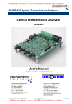
SUNSTAR传感与控制 http://www.sensor-ic.com/ TEL:0755-83376549 FAX:0755-83376182E-MAIL: [email protected]
B6TW SERIES
Workbench
User’s Manual
OMRON CORPORATION
2773680-1A
1
SUNSTAR自动化 http://www.sensor-ic.com/ TEL: 0755-83376489 FAX:0755-83376182 E-MAIL: [email protected]
SUNSTAR传感与控制 http://www.sensor-ic.com/ TEL:0755-83376549 FAX:0755-83376182E-MAIL: [email protected]
Preface
This product supports the development of the touch sensor B6TS series.
To help you use this development tool, this user’s manual provides information about the functions,
performance and usage of this development tool. Also, please reference the specific B6TS product user’s
manual.
When using this product, be sure to observe the following points:
- Users must have knowledge of electronics and software in order to use this product.
- Users must thoroughly read and understand this user’s manual before using this tool.
- This user’s manual must be easily accessible for quick reference.
Before Using this Product
- This product has been developed to support the development of systems using the B6TS series touchsensing IC. Don’t incorporate this product into equipment or use it for other purposes than that for which it is
intended. When using the touch-sensing IC for the following equipment and applications, be sure to contact
our sales representatives, distributors or other OMRON sales personnel in advance.
(A) Nuclear power plant, incineration system, railway control, air traffic controls or avionics, vehicle
facility, medical equipment, entertainment equipment, safety facility and equipment subject to rules
and regulations established by an administrative agency and/or industry groups
(B) Systems, machinery and equipment that may cause injury or property damage
(C) Applications with high safety requirements
- This manual discloses technical information only to explain typical operations and applications of this product.
The above information disclosure for product usage does not mean that the intellectual properties and other
properties of OMRON and the associated third party are guaranteed or licensed.
- This product is a development support tool for systems using the B6TS series touch sensor. Before setting
parameters in B6TS, be sure to fully test and evaluate them for applicability.
OMRON does not take responsibility for the results of development by customers.
- This product has been primarily designed for use in laboratories. The product does not meet UL and IEC
recognition or listing standards; this should be noted particularly when bringing this product overseas.
- Some figures in this user’s manual may differ from the real product, due to version revisions.
- OMRON makes continual efforts to improve the design and performance of this product. Accordingly,
OMRON may alter the specification, design and this user’s manual without prior notice.
- To prevent dangers such as electric shock and fire, and to guarantee product quality, do not repair or modify
the product yourself.
Correct Usage
1. Transportation and Storage
1.1 Do not drop or cause an impact to this product because it is a precision machine.
1.2 Position the package correctly for transportation and storage.
Do not place upside down or let stand this product in order to prevent damage by unnatural forces.
1.3 Do not use or store this product in places exposed to corrosive gas (hydrogen sulfide) or salty wind, or
where it will be subjected to oil/ water spray or direct sunlight
2. Installation
2.1 Do not place heavy objects on this product in order to avoid such unnatural forces.
2.2 When installing this product, pay attention to the installation position. When placed in a constrained
condition, this product may be subjected to great stress in the interface, resulting in contact or relay
errors.
2
SUNSTAR自动化 http://www.sensor-ic.com/ TEL: 0755-83376489 FAX:0755-83376182 E-MAIL: [email protected]
SUNSTAR传感与控制 http://www.sensor-ic.com/ TEL:0755-83376549 FAX:0755-83376182E-MAIL: [email protected]
2.3 When connecting a cable, check the connector direction in advance in order to connect it correctly.
2.4 Connect all the cables before turning on the respective units. In addition, don’t connect or
disconnect the cable while the corresponding unit is being powered up.
2.5 Use this product in a safe place where it will not fall and where other objects will not fall on it.
3. Countermeasures against Static Electricity in Handling this Product
Keep the electric facilities, workbench and workers at the same electric potential.
Put a conductive mat with a surface resistance of 10kΩto 10MΩ on the workbench and ground it.
It is recommended for workers to check that there is no electric leakage in the electric facility and to ground
it using a resistance of approximately 1MΩ for safety. However, be sure to meet the requirements of
safety standards regarding human bodies.
4. Product Environment
4.1 Do not use a voltage exceeding the specified value for each terminal.
4.2 The lower limit of the supply voltage varies for each board. When using this product, confirm the
supply voltage of the board.
4.3 To ensure product performance, use this product in an operating environment under the specified
environmental conditions.
4.4 Pay special attention not to carelessly touch the current-carrying part.
Microsoft® and Windows® are the registered trademarks of Microsoft Corporation in the United States and other countries.
IBM is a registered trademark of International Business Machines Corporation. The other product names described in this
manual are trademarks or registered trademarks of the respective companies.
3
SUNSTAR自动化 http://www.sensor-ic.com/ TEL: 0755-83376489 FAX:0755-83376182 E-MAIL: [email protected]
SUNSTAR传感与控制 http://www.sensor-ic.com/ TEL:0755-83376549 FAX:0755-83376182E-MAIL: [email protected]
CONTENTS
1. Overview
2. Contents
3. Environmental Conditions for Use
3.1 Environmental conditions
3.2 Operating conditions
4. Boards
4.1 B6TS I/F Board
4.1.1 Appearance
4.1.2 Interface
4.1.3 Power supply
4.2 Sample Board
4.2.1 Interface
4.2.2 4ch board
4.2.3 8ch board
4.2.4 16ch board
4.2.4.1 LED function
4.2.4.2 4wire and 3wire SPI switching
5. Usage
5.1 Setup
5.1.1 Software setup
5.1.2 PC setup
5.1.3 Connection
5.2 Usage of Software (B6Tworkbench)
5.2.1 Root menu
5.2.2 Main menu
5.2.3 Com. Port configuration
5.2.4 Circuit Constant
5.2.5 Setup Parameters
5.2.6 Status monitor
5.2.7 Teaching
4
SUNSTAR自动化 http://www.sensor-ic.com/ TEL: 0755-83376489 FAX:0755-83376182 E-MAIL: [email protected]
SUNSTAR传感与控制 http://www.sensor-ic.com/ TEL:0755-83376549 FAX:0755-83376182E-MAIL: [email protected]
1. Overview
This product connects the touch switch IC (B6TS-04LT [4ch type] or B6TS-08NF/08LF [8ch type] or
B6TS-16LF [16ch type]) to a personal computer in odrer to set the operation monitoring parameters.
(Hereinafter, the touch-sensing IC is simply called the B6TS.)
The B6TS is connected to the personal computer via a serial port, or USB-to-serial port adapter.
2. Contents
Check for the presence of all components.
representative.
When there are missing components, please contact your sales
Components delivered
Quantity
B6TS I/F Board (B6TW)
1
Serial communication cable (Dsub 9pin cross)
1
CR-ROM
1
Sample board (*B6TY-S04LT/08NF/08LF/16LF, see
below)
1 (chosen board)
Connection cable
1
* Either of the following sample boards is delivered.
B6TY-S04LT (4ch sample board: B6TS-04LT mounted as a touch-sensing IC)
B6TY-S08NF (8ch sample board: B6TS-08NF mounted as a touch-sensing IC)
B6TY-S08LF (8ch sample board: B6TS-08LF mounted as a touch-sensing IC)
B6TY-S16LT (16ch sample board: B6TS-16LF mounted as a touch-sensing IC)
3. Environmental Conditions for Use
3.1 Environmental Conditions
Item
Temperature
Specification
Use: 0 to 40°
Storage: -15 to 5 0°
Humidity
Use: Below 85%RH (no dew condensation or freezing)
Storage: Below 85%RH (no dew condensation or freezing)
Ambient gas
There must not be corrosive gas environment.
3.2 Operating Environment
Item
Operating Environment
Host computer
IBM PC/AT compatible
OS
Windows®2000 or Windows®XP
Memory capacity
64MB or more
Hard disk capacity
20MB or more
Interface *
Serial port (COM) 38400bps [for B6TS I/F board connection]
* When a personal computer is not equiped with a serial port, use the
USB-serial conversion cable.
5
SUNSTAR自动化 http://www.sensor-ic.com/ TEL: 0755-83376489 FAX:0755-83376182 E-MAIL: [email protected]
SUNSTAR传感与控制 http://www.sensor-ic.com/ TEL:0755-83376549 FAX:0755-83376182E-MAIL: [email protected]
Item
Operating Environment
Supply voltage
B6TS Interface Board: 3.0-5.5DVC
B6TY-S04LT : 3.1-5.5DVC
B6TY-S08NF : 4.5-5.5DVC
B6TY-S08LF : 3.0-5.5DVC
B6TY-S16LF : 3.0-5.5DVC
* Supply voltage varies between the boards.
be sure to confirm supply voltage.
Power consumption
When using this product,
Below 200mA (including the B6TS Interface board and sample board)
4. Boards
4.1 B6TS Interface Board
4.1.1 Appearance
4.1.2 Interface
Configuration
Connector
Switch
LED
Circuit symbol
Function
CN1: Power connector
Connector for power supply to the power connector. For details,
refer to the following power specifications.
CN2: Communication
connector
Communication connector for connecting a personal computer
port via a serial connection cable.
CN3: Communication
connector
Communication connector for connecting a sample board such as
a B6TS chip.
CN4: Power connector
Power supply connector (not mounted) using the same line as
CN1.
S1: Power supply
Power Switch for power supply from CN1 (or CN4).
S2: Ext.Power (External
power supply)
External power supply switch for connecting the CN3 power line
(Vdd) to the power line of the B6TS I/F.
When this switch is turned on, the B6TS module (sample
board/user system) connection to CN3 is powered or the B6TS I/F
board is activated through the B6TS module power supply.
S3: Maintenance mode
This must be generally set to Norm for maintenance.
(The maintenance mode is set at UP and regular operations
cannot be performed.)
LED1: Power supply
This LED indicates that power is being supplied to this board.
LED2: Ext.Power External
power supply
This LED indicates that the external supply voltage S2 is ON.
When S2 is ON, the voltage line (Vdd) of CN3 is connected to that
of the B6TS I/F board.
The following table shows the pin assignments of CN3 on this sample board.
Refer to this table when connecting this sample board to your design system temporarily for
operation check.
6
SUNSTAR自动化 http://www.sensor-ic.com/ TEL: 0755-83376489 FAX:0755-83376182 E-MAIL: [email protected]
SUNSTAR传感与控制 http://www.sensor-ic.com/ TEL:0755-83376549 FAX:0755-83376182E-MAIL: [email protected]
Before connecting this board, be careful to supply voltage and connector direction.
When excess voltage is supplied to this sample board, it may be damaged.
Reference)
Board connector (CN3): 2.54 mm pitch 10-pin connector (straight) Hirose HIF3FC-10PA254DSA72 Cable connector : Hirose HIF3BA-10DA-2.54R
Pin No.
Signal name
1
Vdd
2
SETUP
3
MISO
4
MOSI/SD
5
SCK
6
SCS
7
MEAS
8
CHG
9
RESET
10
GND
Remarks
Power supply
For B6TY-S04LT/16LF (3wire SPI) , no signal connection is
required.
SD for B6TY-S04LT/08LF/16LF (3wire SPI)
MOSI for B6TY-S08NF/16LF (4wire SPI).
For B6TY-S08NF, no signal connection is required.
Signal ground
4.1.3 Power supply
The B6TS I/F board requires a voltage supply of 3.0 to 5.5DVC.
However, pay attention to supply voltage depending on the touch sensor to be connected.
- When the touch-sensing IC is B6TS-08NF:
Because the operating voltage of B6TS-08NF is 4.5 to 5.5DVC, be sure to use the B6TS I/F
board at 4.5 to 5.5DVC.
- When the touch-sensing IC is other type
The operating voltage is 3.0 to 5.5DVC. Be sure to use the B6TS I/F board at 3.0 to 5.5DVC.
(Considering the voltage drop in the internal protection circuit when using the sample board, be
sure to use a voltage of 3.1C to 5.5DVC.)
The B6TS I/F (interface) board has been designed, considering two main kinds of power supply; the
ripple ratio of this power supply should be less than 3%.
A. When an external power supply is connected to CN1 (or CN4):
When the sample board is used, i.e., voltage is supplied from the B6TS I/F board to the B6TS
chip, connect an adequate external power supply to CN1 (or CN4) and then turn on S1 and S2.
B. When voltage is supplied from CN3:
When B6TS is operated using the power supply of a user system for monitoring, connect the
power line of CN3 to the user system. (For this connection, see 6. External Connector.)
Without connecting an external power supply to CN1 (or CN4), turn off S1 and turn on S2.
4.2
Sample Board
Either of the following sample boards is delivered according to the model type.
B6TW
B6TW-S04LT
B6TW-S08NF
B6TW-S08LF
B6TW-S16LF
Sample board
B6TY-S04LT (4ch sample board:
B6TY-S08NF (8ch sample board:
B6TY-S08LF (8ch sample board:
B6TY-S16LF (16ch sample board:
B6TS-04LT mounted as a touch-sensing IC)
B6TS-08NF mounted as a touch-sensing IC)
B6TS-08LF mounted as a touch-sensing IC)
B6TS-16LF mounted as a touch-sensing IC)
7
SUNSTAR自动化 http://www.sensor-ic.com/ TEL: 0755-83376489 FAX:0755-83376182 E-MAIL: [email protected]
SUNSTAR传感与控制 http://www.sensor-ic.com/ TEL:0755-83376549 FAX:0755-83376182E-MAIL: [email protected]
4.2.1 Interface
Configuration
Circuit symbol
Function
Connector
CN1:
Communication
connector
Connector for connecting the B6TS I/F board
Touch
electrode
Ch0 to n
As many touch electrodes as B6TS channels are mounted on the board.
The size of a touch electrode is 12 × 12 mm (10mm at 16ch board).
LED:
04LT
08NF/LF : LED1-8
LEDs connected to On/Off output terminals (OUTx) from B6TS Because
B6TS uses the On:/Off output and serial communication output,
switching the same pin, LED connected to the pin used for serial
communication blinks during communication.
16LF
16LF does not have parallel out put, and control LED via micro
controller.
: LED1 – 4
:
D1-18
D17 (OUT_A) and D18 (OUT_B) are drive by B6TS.
Reference: Board connector (CN1): 2.54 mm pitch 10-pin connector (straight) Hirose HIF3FC-10PA254DSA72 Cable connector : Hirose HIF3BA-10DA-2.54R
Pin No.
Signal
name
1
Vdd
2
SETUP
3
MISO
4
MOSI/SD
5
SCK
6
SCS
7
MEAS
8
CHG
9
RESET
10
GND
Remarks
Power supply
For B6TY-S04LT/16LF (3wire SPI) , no signal connection is
required.
SD for B6TY-S04LT/08LF/16LF (3wire SPI)
MOSI for B6TY-S08NF/16LF (4wire SPI).
For B6TY-S08NF, no signal connection is required.
Signal ground
8
SUNSTAR自动化 http://www.sensor-ic.com/ TEL: 0755-83376489 FAX:0755-83376182 E-MAIL: [email protected]
SUNSTAR传感与控制 http://www.sensor-ic.com/ TEL:0755-83376549 FAX:0755-83376182E-MAIL: [email protected]
4.2.2 4ch Board
B6TY-S04LT
Power supply voltage
Serial interface
Board size
Electrode size
Passive devices
:
:
:
:
CH0
3.1 to 5.5V
3-wire SPI
57mm x 115mm
12mm x 12mm
CH1
Cr
Rr
Cc
Rc
CH2
CH3
CH2
CH3
CH2
CH3
18pF
10Kohm
0.1μF
2.7Kohm
Appearance
4.2.3 8ch Board
B6TY-S08NF
Power supply voltage
Serial interface
Board size
Electrode size
Passive devices
:
:
:
:
CH0
4.5 to 5.5V
3-wire SPI
57mm x 115mm
12mm x 12mm
CH1
Cr
Rr
Cc
Rc
18pF
10Kohm
0.1μF
5.6Kohm
Appearance
B6TY-S08LF
Power supply voltage
Serial interface
Board size
Electrode size
Passive devices
:
:
:
:
CH0
3.0 to 5.5V
3-wire SPI
57mm x 115mm
12mm x 12mm
CH1
Cr
Rr
Cc
Rc
18pF
10Kohm
0.1μF
3.9Kohm
Appearance
9
SUNSTAR自动化 http://www.sensor-ic.com/ TEL: 0755-83376489 FAX:0755-83376182 E-MAIL: [email protected]
SUNSTAR传感与控制 http://www.sensor-ic.com/ TEL:0755-83376549 FAX:0755-83376182E-MAIL: [email protected]
4.2.4 16ch Board
B6TY-S16LF
Power supply voltage
:
3.0 to 5.5V
Serial interface
:
4-wire SPI (3-wire SPI)
Board size
:
67mm x 170mm
Electrode size
:
10mm x 10mm
Passive devices
CH0
CH1
CH2
CH3
CH4
CH5
CH6
CH7
Cr
24pF
15pF
24pF
15pF
Rr
10kohm
Cc
0.1uF
Rc
560ohm
680ohm
560ohm
680ohm
CH8
CH9
CH10
CH11
CH12
CH13
CH14
CH15
Cr
15pF
24pF
Rr
10kohm
Cc
0.1uF
Rc
680ohm
680ohm
Appearance
4.2.4.1 LED control
B6TY-S16LF is using LED driver microcontroller (U2) to control LED (D1 to D16).
LED driver U2 receive touch event from B6TS via UART and turn on the LED.
SW1 choose this LED driver function enable and disable.
Right
Left
(ON) : LED control and UART enable
(OFF) : LED control and UART disable
O
N
LED enable
O
N
When communicate with Workbench, LED must be disabled (SW off).
LED disable
4.2.4.2 4-wire or 3-wire SPI selection
B6TS-16LF can select SPI mode 4 wire(/SCS、SCK、MOSI、MISO)or 3wire(/SCS、SCK、
SD).
To select the mode, IFSEL(No.11 terminal)is
Pull up
:
4 wire SPI
Pull down
:
3 wire SPI
At B6TY-S16LF board, 4 wire SPI is selected by using R55 pull up
resister. To change 3 wire mode, remove R55 and use R56
(10kΩ).
B6TS- 16
R55
IFSEL 11
10
SUNSTAR自动化 http://www.sensor-ic.com/ TEL: 0755-83376489 FAX:0755-83376182 E-MAIL: [email protected]
R56
Not mounted
SUNSTAR传感与控制 http://www.sensor-ic.com/ TEL:0755-83376549 FAX:0755-83376182E-MAIL: [email protected]
5.
Usage
5.1
Setup
5.1.1 Setting up Software (B6Tworkbench Software)
1. Set the accessory CD-ROM in the CD-ROM drive of the personal computer.
2. Execute the installation program stored on the CD-ROM. The installation program varies from
chip to chip. Use the installation program corresponding to the chip in use.
\B6Tsetup-English\B6TSetupALL-eng-v2.0.3.exe
3. B6Tworkbench installation starts. After checking the messages displayed on the screen,
begin the installation.
*1 Software is installed in the following folders.
\Program Files\OMRON\B6TWorkbench_2
*2 Installation must be performed by those with administrator privileges. Log in as a user with
administrator privileges.
5.1.2 Setting up PC
Set up PC COM port as follows when using COM port.
At WindowsXP. Set from START – Control panel – System – Hardware – Device manager –
Port (COM / LPT)
Communication setting
Transfer rate :
Data bit length :
Varity
:
Stop bit
:
38400bps
8bit
N/A
1 bit
5.1.3 Connecting Device
Two connection methods are available depending on the type of usage.
Set up connection A or B depending on the type of usage.
A. When the power supply is connected to the B6TS I/F board, voltage is supplied from the B6TS I/F
board to the B6TS chip. This method is used when the sample board is used.
1. Connect the personal computer to the CN2 connector of the B6TS I/F board (B6TW) with an
accessory communication cable.
2. Connect the CN3 connector of the B6TS I/F board to the sample board (or the user system)
with a connection cable.
(When the user system and B6TS I/F board are connected, prepare a connection cable.)
3. Supply voltage to the CN1 connector (or CN4) of the B6TS I/F board.
When the sample board is used, supply the following voltage.
4. Turn on the switches S1 and S2 in order to supply voltage to the B6TS I/F board and sample
board (or the user system).
Personal
computer
Sample board or
user system with B6TS
Serial communication
cable
Connection
cable
DC power
supply
B6TS
11I/F board (B6TW)
SUNSTAR自动化 http://www.sensor-ic.com/ TEL: 0755-83376489 FAX:0755-83376182 E-MAIL: [email protected]
SUNSTAR传感与控制 http://www.sensor-ic.com/ TEL:0755-83376549 FAX:0755-83376182E-MAIL: [email protected]
B. When voltage is supplied from the user system to the B6TS I/F board:
This method is used when the B6TS is operated, using the power supply of the user system, for
status monitoring.
1. Connect the personal computer to the CN2 connector of the B6TS I/F board (B6TW) with an
accessory communication cable.
2. Connect the user system B6TS to the CN3 connector of the B6TS I/F board.
(Prepare the connection cable yourself.)
3. Turn on the S2 switch in order to supply voltage from the user system to the B6TS I/F board;
the ripple factor of the power supply should be less than 3%.
Personal Computer
User system with B6TS
Serial communication
cable
Connection
cable
User system power
supply
5.
B6TS I/F (development) board
(B6TW)
2 Using the Software (B6Tworkbench)
5.2.1 Start (Root Menu)
Start B6TSWorkbench from the Start menu on the personal computer. Select the B6TS chip
type you are using.
Select target chip type
Terminate B6T Workbench
12
SUNSTAR自动化 http://www.sensor-ic.com/ TEL: 0755-83376489 FAX:0755-83376182 E-MAIL: [email protected]
SUNSTAR传感与控制 http://www.sensor-ic.com/ TEL:0755-83376549 FAX:0755-83376182E-MAIL: [email protected]
5.2.2 Main menu
Once the software is selected by root menu, main menu for each chip appears.
The following description is given using as an example of the B6TS-04LT software.
The touch capacitance and the constants for external devices
(components) can be obtained from the electrode area.
The parameters set in B6TS can be read and written.
The operating condition of B6TS is displayed in graphs.
The On/Off threshold of B6TS is automatically obtained according
to real user electrode touching.
The port settings being used for communication, with the B6TW.
Ending the B6Workbench program.
5.2.3 Com. Port configuration
Set the ports to be used for communication with the B6TS I/F board. Click the Communication
Setup button on the main menu. A window appears as shown in the following figure.
Select a port connected to the B6TS I/F board.
After entering the setting, click the OK button.
13
SUNSTAR自动化 http://www.sensor-ic.com/ TEL: 0755-83376489 FAX:0755-83376182 E-MAIL: [email protected]
SUNSTAR传感与控制 http://www.sensor-ic.com/ TEL:0755-83376549 FAX:0755-83376182E-MAIL: [email protected]
5.2.4 Circuit Constant
The capacitance can be estimated from the area of an electrode. In addition, the constant and
measurement (estimate) of an external circuit component is displayed - from the estimated
capacitance. Click the Circuit Constant button on the main menu. A window appears as
shown in the following figure.
The following items can be input. A range of input values can be displayed within the window.
- Electrode shape (rectangle or circle) dimensions
- Cable length from electrode to B6TS (l)
- Electrode surface panel thickness (d) = Distance between electrode at touch and finger
- Surface panel relative permittivity (εr)
* The values of εr are about 1 for air, 2 to 4 for plastics (acrylic fiber, etc.) and 3 to
5 for glass.
Input the above values and click the Capacitance Calculation button.
The estimated values of the following items are displayed:
- Estimated capacitance value (non-touch capacitance, difference between touch
capacitance and non-touch capacitance)
- Recommended external circuit constant values (value selected from E12 series)
- Estimated B6TS measurement (standard value [REFx] and On determination change
standard value [THRx] at this time)
- (REFx indicates a non-touch measurement, THRx indicates a value of two thirds
the difference between the touch and non-touch measurements.)
[Notes]
1. Each display value is an approximate value.
2. The capacitance significantly varies depending on the ambient metal (distance from wiring pattern,
board shape or chassis to electrode). For this reason, remember that external circuit constants
need be changed occasionally and B6TS measurements may differ from those described above.
Values listed here are only for reference. Be sure to check whether B6TS measurements (touch
and non-touch measurements) are effective on the system of your actual machines.
3. When the area of an electrode is small and the panel thickness (d) is large, the change between
touch and non-touch capacitances may be extremely small. In this case, touch measurement
becomes difficult and the message “ΔC is too small and touch measurement may not be possible” is
displayed.
Even in this case, the capacitance estimate is displayed. However, the value “0” is displayed as
a measurement estimate for the external circuit constant or B6TS.
4. B6TS-08LFand B6TS-16LF has two different characteristics at each channel, and simulation
results are also divided to 2 type.
14
SUNSTAR自动化 http://www.sensor-ic.com/ TEL: 0755-83376489 FAX:0755-83376182 E-MAIL: [email protected]
SUNSTAR传感与控制 http://www.sensor-ic.com/ TEL:0755-83376549 FAX:0755-83376182E-MAIL: [email protected]
5.2.5 Setup Parameters
The B6TS setup parameters can be read and written via the B6TS I/F (development) board.
Click the Setup Parameters button on the main menu. A window appears as shown in the
following figure.
Click the [Read from B6TS] button to display the current B6TS parameters. When this button
is first clicked after this software has been activated, the message “B6Tworkbench is not
connected yet” may be displayed. In this case, click the button again.
When this [Read from B6TS] button is clicked after the necessary items are set, the parameters
are written to B6TS.
In addition, the [Write to file] or [Read from file] button can be used to save the current display
parameters in a file of the personal computer or to read them from the file.
Explanation of Parameters
Operation Mode (Command MODE : 0x3E)
Output Mode (COM : 0x3E.bit0)
The output configuration of the B6TS detection results is selected.
Data communication (serial communication) using either serial communication (SPIcompliant) or by turning the terminal On or Off depending on the detection result
(producing an On/Off output) can be selected.
CHG Active Condition (CHG : 0x3E.bit1)
The B6TS measurement status can be monitored using the CHG signals.
Either turning the GHC terminal on “High” for every measurement (end of
measurement) or turning it on “High” (On/Off status change) for every status change
from touch to non-touch and vice versa in any measurement channel can be selected.
Drift Compensation (DC : 0x3E.bit2)
The touch/non-touch measurement result varies depending on ambient conditions.
Whether or not to compensate for the touch/non-touch measurement according to this
change can be selected. When “No compensation” is selected, touch/non-touch
evaluation takes place using the setting On/Off threshold value. When
“Compensation” is selected, the On/Off threshold is compensated dynamically,
depending on the ambient conditions.
However, note that drift compensation is effective at times without touch assessment.
No drift compensation takes place, even when “compensation” has been selected so
15
SUNSTAR自动化 http://www.sensor-ic.com/ TEL: 0755-83376489 FAX:0755-83376182 E-MAIL: [email protected]
SUNSTAR传感与控制 http://www.sensor-ic.com/ TEL:0755-83376549 FAX:0755-83376182E-MAIL: [email protected]
long as “touch” is judged - as the measurement result of B6TS.
Drift Compensation type (DCF : 0x3E.bit3)
This parameter is enabled when select ‘enable’ at Drift Compensation (DC).
Note : This parameter is only for B6TS-16LF.
All
REFx only
:Compensate the threshold as to REFx:THRx=CREFx:CTHRx.
:Compensate at CTHRx=THRx
Teaching Measurement Count (TCAL : 0x3A)
The upper limit of measurement is defined for teaching (from actual touch to Of/Off
threshold automatic calculation). During teaching, measurement takes place up to the
number of times decided by multiplying the value specified here by 32. Because it takes
20 to 100mS for single measurement (note that this value varies depending on the external
circuit constant), a touch of about 6 to 30 seconds is required if a value of 10 is specified
here. (For details, refer to 5.2.7 Teaching.)
A value from 0 to 255 can be specified.
When “0” is set for teaching, only the reference value (REFx) is updated. When “1” or any
greater value is specified, the reference value (REFx), On determination change (THRx)
and hysteresis (HYSx) are updated.
Note : B6TS-16LF does not have this parameter.
Accumulated Judgment Count (ACD : 0x3C)
When a measurement exceeds an On/Off threshold up to the number of times specified
here plus 1, “touch” is determined (assessed). For example, if “2” is specified here,
“touch” is determined (assessed) only when the measurement exceeds the On/Off value
consecutively 3 times.
A value from 0 to 255 can be specified.
Measurement Interval (SLP : 0x3D)
The time interval from one measurement to another (sleep time) is defined.
A value from 0 to 255 can be specified.
When “1” is specified, the sleep time is about 10mS. When “0” is specified, measurement
takes place consecutively.
Max successive ON count (MSA:0x36)
MSA is the mode after the ON condition. After keeping on condition during MSA×64 times,
identify the condition as OFF and start drift compensation again. When choose 0, this function
is disabled. (Default) Note : This parameter is only for B6TS-08LF/16LF.
Drift correction interval (DCI:0x37)
Set the drift compensation interval.
Drift compensation is done every 2(DCI) times measurement, during the OFF condition.
Default=5 (25=32 times. This is almost 2 seconds.) Note : This parameter is only for B6TS08LF/16LF.
Pole (BPOL:0x38)
Set output logic for OUTx terminal.
ON/OFF result which appear to BDATA are fixed to Low active.
for B6TS-08LF/16LF.
Note : This parameter is only
Setting the Value of Each Channel
Measurement Enable (CHEN : 0x39)/Toggle Operation (TOG : 0x3B)
Channel measurement and B6TS-output On/Off signal operations are defined.
[No measurement]
– Channel measurement does not take place.
[Momentary operation] – On output takes place at a touch.
[Toggle operation]
– On/Off output takes place alternately every touch.
Reference Value (REFx : from 0x40)
The non-touch measurement (approximate) is defined. For actual setting, use the
operation monitor.
16
SUNSTAR自动化 http://www.sensor-ic.com/ TEL: 0755-83376489 FAX:0755-83376182 E-MAIL: [email protected]
SUNSTAR传感与控制 http://www.sensor-ic.com/ TEL:0755-83376549 FAX:0755-83376182E-MAIL: [email protected]
On determination change (THRx : from 0x41)
“Touch” is determined (assessed) when a difference between the measurement and the
reference value is equal to the value defined here; namely, Threshold (On/Off threshold) in
non-touch-to-touch status change = REFx - THRx
For actual setting, use the operation monitor. In an environment with relatively low noise, it
is desirable for this value to be 50 to 70% of change due to touch.
Hysteresis (HYSx)
The hysteresis value for touch-to-non-touch status change is defined.
Threshold for touch-to-non-touch status change = REFx – THRx + HYSx
For actual setting, use the operation monitor. This value should be appropriate for the
change due to noise.
On Judging Ratio (RTHRx : from 0x42)
The ratio for On determination change (THRx) compared to measurement change due to
touch during teaching (from actual touch to automatic On/Off threshold calculation) is
defined. A value from 0 to 15 can be defined. (For details, refer to 5.3 Teaching.)
Assume that the measurement varies for touch by ΔA during teaching. At this time, the
new THRx to be updated by teaching is obtained using the following expression:
Updated result of On determination change (THRx) =ΔA × (On determination ratio +1) / 16
For example, when “10” is set for the On determination ratio, the following result is
obtained. Updated result of On determination change is (THRx) =ΔA × (10 + 1)/16 ≈ 0.69ΔA (about
70% of Δa)
Hysteresis Ratio (RHYSx : from 0x43)
As in the On determination ratio, the ratio of hysteresis (HYSx) compared to measurement
change due to touch during teaching is defined. A value from 0 to 15 can be defined.
(For details, refer to 5.3 Teaching.)
Assume that the measurement varies for touch by ΔA during teaching. At this time, the
new HYSx to be updated by teaching is obtained using the following expression: (Unlike
the On determination ratio, note that the value is not incremented by one.)
Updated result of hysteresis is (HYSx) = ΔA × (hysteresis ratio) / 16
For example, when “2” is set for the On determination ratio, the following result is obtained.
Updated result of hysteresis is (HYSx) =ΔA × 2/16 ≈ 0.13ΔA (about 13% of Δa)
Measurement
Electrode touch
HYSx =ΔA × (hysteresis ratio) / 16
Time
17
SUNSTAR自动化 http://www.sensor-ic.com/ TEL: 0755-83376489 FAX:0755-83376182 E-MAIL: [email protected]
SUNSTAR传感与控制 http://www.sensor-ic.com/ TEL:0755-83376549 FAX:0755-83376182E-MAIL: [email protected]
5.2.6
Status Monitor
The measurement state of B6TS can be monitored. Click “Operation Monitor” on the main
menu. A window appears as shown in the following figure. Click the Start button at the lower
left corner of the window, and the measurement results of B6TS will be read and displayed in
graphs. When the operation monitor is running, B6TS is automatically placed in serial
communication mode. (The show window is an example of B6TS-08LF)
The time interval for reading data from B6TS is set (defined). When the
time interval is short, there is no time for calculation and measurement
update cannot be performed.
When no measurement update takes place, set a longer time for reading.
Graph display
Red – Measurement
Blue dotted line - Current offset value (=CREFx)
Green dotted line - Current On/Off threshold (=CREFx - CTHRx)
The graph is extended, reduced or
moved. To center the measurement
value in the graph, click the ~ button.
Display data is written to a file. Because this file
is created in csv format, and data can be read via
Excel.
Current offset value (CREFx). The current On
determination change (CTHRx) is displayed.
The value automatically changes during drift
compensation. For setting without drift
compensation, these values are identical to the
REFx and THRx values of the setup parameter.
On/Off determination results:
When “On” is determined as the result
of measurement, a red stripe is
displayed.
Results of the most recent
8 measurements (numeric display)
18
SUNSTAR自动化 http://www.sensor-ic.com/ TEL: 0755-83376489 FAX:0755-83376182 E-MAIL: [email protected]
SUNSTAR传感与控制 http://www.sensor-ic.com/ TEL:0755-83376549 FAX:0755-83376182E-MAIL: [email protected]
5.2.7 Teaching
5.2.7.1
Overview of Teaching
Parameters such as the On determination change can be set automatically by actually
touching an electrode; this operation is called “Teaching.” Some preparations are required for
teaching. The following shows a teaching flow diagram, including preparations.
The reference value (REFx), On determination change (THRx) and hysteresis (HYSx) are
properly updated by teaching and the results are saved in the EEPROM of B6TS.
(Hereinafter, these three parameters are called teaching parameters.)
1. Preparation for teaching: Set the following values in the Setup Parameter window.
On determination change (THRx), hysteresis (HYSx), On determination ratio (RTHRx), hysteresis
(RHYSx) and teaching measurement count (TCAL)
For setting, use the operation monitor as necessary.
↓
2. Teaching:
Touch each electrode three times (or more).
↓
3. Confirmation of teaching results:
The results of teaching can be confirmed on the setup parameter window.
The following describes these steps in order.
5.2.7.2 Teaching at B6TS-04LT and 08NF/LF
Preparation for Teaching
For teaching, prepare some parameters in advance. Click the Set Parameter button on the
main menu to open the Parameter Setup window.
First, read the current parameters of B6TS by clicking the B6TS → Workbench Read button,
modify their items if necessary, and write them to B6TS by clicking the Workbench → B6TS
Write button.
The following five types of parameters must be specified.
[Notes]
No measurement takes place for channels when the Measurement Enable (CHEN)/Toggle
(TOG) parameter has been set to No measurement. Accordingly, teaching cannot be
performed for these channels. For the above reason, it is not necessary to specify the
following parameters for channels where “No measurement” has been set.
- Teaching Measurement Count (TCAL)
The upper limit (count) of teaching is defined. During teaching, measurement takes
place up to the number of times defined by multiplying the value specified here by 32.
Because it takes 20 to 100mS for single measurement (note that this value varies
depending on the external circuit constant), a touch of about 6 to 30 seconds is required
if a value of 10 is specified here.
(Hereinafter, this time is called the teaching measurement time.)
When no touching takes place in a given teaching measurement time after teaching
starts, a teaching error is assumed and no parameter update takes place.
However, when this value is 0, only the reference value (REFx) is taught. In this case,
no teaching error is assumed because no touch is required.
A value from 0 to 255 can be specified.
19
SUNSTAR自动化 http://www.sensor-ic.com/ TEL: 0755-83376489 FAX:0755-83376182 E-MAIL: [email protected]
SUNSTAR传感与控制 http://www.sensor-ic.com/ TEL:0755-83376549 FAX:0755-83376182E-MAIL: [email protected]
- On Determination Change (THRx)
The change (approximate value) of measurement at electrode touch is defined. This
parameter must be defined beforehand to differentiate measurement change due to noise
(noise change) from change due to electrode touch.
At teaching, “touch” is determined when a detected change is a half of the value defined
here. Accordingly, the value defined here may be an approximate value at which the
measurement may change at electrode touch.
- Hysteresis (HYSx)
A hysteresis (approximate value) is defined.
noise is relatively low.
- On Determination Ratio (RTHRx)
A value of 0 may be defined here when
- Hysteresis Ratio (RHYSx)
The ratio of On determination change (HTEx) or hysteresis (HYSx) compared to
measurement change due to touch is defined. A value from 0 to 15 can be defined.
Touch each electrode three times (or more) for teaching.
Next, B6TS internally calculates the minimum value of change for each electrode
(minimum change). Assuming that the minimum change isΔA, the On determination
change and hysteresis are calculated as followed.
Updated result of On determination change is (THRx) =ΔA × (On judging ratio +1) / 16
Updated result of hysteresis is (HYSx) = ΔA × (hysteresis ratio) / 16
For example, the following expression is derived when the On determinationratio is 10
and hysteresis is 2.
Updated result of On determination change is (THRx) =ΔA × (10 + 1)/16 ≈ 0.69ΔA (about
70% of Δa)
Updated result of hysteresis is (HYSx) =ΔA × 2/16 0.13ΔA (about 13% of Δa)
When noise is relatively low in an environment, the proper value is 7 to 10 for the On
determination ratio and 1 to 1 for the hysteresis ratio. In this case, the On determination
Measurement
Electrode touch
THRx=ΔA × (On determination ratio [RTHRx] + 1) / 16
HYSx=ΔA × (hysteresis ratio [RHYSx]) / 16
Time
ratio (THRx) is 50 to 70% ofΔA and the hysteresis ratio is 6 to 13% ofΔA.
As described above, set the five parameters properly, and then click the Workbench->B6TS Write button
to write them to B6TS.
Execution of Teaching
After setting the parameters, execute teaching. Click the Teaching button on the main menu.
The following window appears as shown in the figure.
20
SUNSTAR自动化 http://www.sensor-ic.com/ TEL: 0755-83376489 FAX:0755-83376182 E-MAIL: [email protected]
SUNSTAR传感与控制 http://www.sensor-ic.com/ TEL:0755-83376549 FAX:0755-83376182E-MAIL: [email protected]
Click the Start Teaching button.
After a while, the message “Touch each electrode three times or more” appears as shown in the
below figure. Unless this message appears, don’t touch the electrode.
Once this message appears, touch each electrode.
You may touch the electrodes in any order.
However, it is recommended to change the electrode
touch order as follows to differentiate one touch from
another.
Ch0 → Ch1 → Ch2 → Ch3 → Ch0 ↑ Ch1 → …
Notes:
1. The touch time is limited.
(For teaching measurement time, see “Teaching Measurement
Count” in 5.3.2 “Preparation for Teaching.”
When you don’t touch each electrode three times or more, a teaching error is assumed and
the teaching parameter update does not take place for all channels.
2. When the touch count exceeds the upper limit (number of channels for measurement × 4),
further measurement does not take place and teaching terminates. Namely, when all
channels are used in B6TS-04LT [for 4ch], teaching terminates when the touch count
reaches 16. Similarly, when all channels are used in B6TS-08NF [for 8ch], teaching
terminates when the teaching count reaches 32.
3. When there is a channel for which “No measurement” has been set on the Setup Parameter
window, no touch measurement takes place for the channel. Accordingly, teaching cannot
be performed for these channels.
Even in this case, when the touch count exceeds the upper limit (number of channels for
measurement × 4), further measurement does not take place and teaching terminates. For
example, assume that “No measurement” has been set for a channel in B6TS-04LT [for
4ch]. In this case, teaching terminates when the touch count reaches 12 (3 × 4 =12)
because the number of channels for measurement is 3. This is true for B6TS-08NF [for
8ch].
21
SUNSTAR自动化 http://www.sensor-ic.com/ TEL: 0755-83376489 FAX:0755-83376182 E-MAIL: [email protected]
SUNSTAR传感与控制 http://www.sensor-ic.com/ TEL:0755-83376549 FAX:0755-83376182E-MAIL: [email protected]
When you touch each electrode three times or more and the teaching measurement time is
over, the message shown in the below figure appears to indicate the completion of teaching.
* When the set teaching measurement time is long (i.e., the teaching measurement count
(TCAL) value is large), you may touch each electrode four times to terminate teaching.
When teaching does not terminate normally because you didn’t touch any electrode within the
given teaching measurement time, the message shown in the below figure appears.
- When you cannot touch any electrode within the given teaching measurement time, specify a
larger teaching measurement count (TCAL) value on the Setup Parameter Definition window
and attempt teaching again.
- If this message appears even when you’ve touched each electrode normally, check whether
or not the values for On determination change (THRx) and hysteresis (HYSx) are properly set
for actual measurement.
* While the teaching window is open, you cannot move to other windows such as the Setup
Parameter window and Operation Monitor window. In this case, close the teaching window
once, then move to the other window.
22
SUNSTAR自动化 http://www.sensor-ic.com/ TEL: 0755-83376489 FAX:0755-83376182 E-MAIL: [email protected]
SUNSTAR传感与控制 http://www.sensor-ic.com/ TEL:0755-83376549 FAX:0755-83376182E-MAIL: [email protected]
5.2.4
Confirmation of Teaching Results
Once teaching terminates, confirm that the teaching parameters have been set properly on the
Setup Parameter window.
Check whether these three
teaching parameters are in the
proper range for each channel.
23
SUNSTAR自动化 http://www.sensor-ic.com/ TEL: 0755-83376489 FAX:0755-83376182 E-MAIL: [email protected]
SUNSTAR传感与控制 http://www.sensor-ic.com/ TEL:0755-83376549 FAX:0755-83376182E-MAIL: [email protected]
5.2.7.4 Teaching at B6TS-16LF
B6TS-16LF uses a different window for teaching, as shown below.
Select ‘Teaching’ button from main menu, and open the window.
(1)
(2)
(3)
(4)
(5)
(1) Read from B6T the RTHRx and RHYSx data from B6TS. Change each number if needed.
(2) Start teaching mode.
Measurement condition is appearing to the window. Touch each CH 3 times by checking the ON
condition with graph. (A red bar appears below each of the graphs.)
When finished touching at
least three times each, push the ‘STOP’ button.
(3) Calculate threshold from sampling data.
In case error message appears, please try sampling again.
(4) Write to B6T the results of the above teaching process.
(5) Close teaching mode. (Verify the results in Setup Parameters)
24
SUNSTAR自动化 http://www.sensor-ic.com/ TEL: 0755-83376489 FAX:0755-83376182 E-MAIL: [email protected]
SUNSTAR传感与控制 http://www.sensor-ic.com/ TEL:0755-83376549 FAX:0755-83376182E-MAIL: [email protected]
GUARANTY
1. Term of Guaranty
The term of guarantee for this product is one year after procurement or delivery to a specified site.
2. Scope of Guaranty
If this product breaks down during the above term of guarantee for causes attributable to OMRON, we
will provide a replacement or repair the product at your site (procurement site) for free. Nevertheless,
OMRON does not guarantee the product if it breaks down due to any of the following causes:
a) Product usage in conditions, environment or following instructions other than those specified in this
specification, catalog, instructions manual or users manual (hereinafter simply called the catalog).
b) Causes that cannot be attributed to this product
c) Product modification or repair by companies other than OMRON
d) Product usage not intended initially by OMRON
e) Causes that cannot be predicted by science or technology at product shipment
f) Extraordinary natural phenomena such as natural disasters and hazards
Notice in particular that this guaranty is limited to our product itself and does not cover
incidental damage as a result of using our product.
3. Scope of Service
The price of this product does not include the cost of on-site technical service by engineers.
When on-site service is required, contact our sales representative.
4. Scope of Applicability
The following terms assume the trade and use of this product in Japan.
When using this product overseas, contact our sales representative in advance.
25
SUNSTAR自动化 http://www.sensor-ic.com/ TEL: 0755-83376489 FAX:0755-83376182 E-MAIL: [email protected]