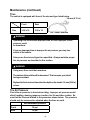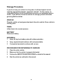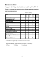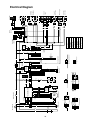
1
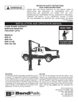
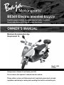
BE500 Electric assisted bicycle
Read this manual carefully. It contains important safety information.
No one under the age of 16 should operate this vehicle.
OWNER’S MANUAL
Minimum Recommended Age
Requirement 16
Rev.G (US)
031009
Always wear a helmet; It could save your Life!
Do not remove this operator’s manual from this vehicle.
Please obtain, review, and follow provincial / municipal government acts and
regulations pertaining to owning and operating this electric assisted bicycle.
Congratulations on your purchase of the BAJA INC. BE500 Electric
assisted bicycle.
Your vehicle is warranted to be free of manufacturing defects in the
material of workmanship for a period of 90 days from the date of
purchase. During the warranty period BAJA INC. will at its option,
repair, provide replacement parts or replace your BAJA INC. vehicle
at no charge. This warranty does not cover normal wear items or
damage caused by neglect or misuse of the product.
Motor Warranty – 90 days
Frame Warranty – 90 days
Warranty is void if:
Frame is bent or broken due to abuse
Wheels are bent or broken
Fender bent or broken due to abuse
Any sign of impact, accident, jumping, spin-outs or roll over.
BAJA INC. is not liable for any damage claim or liability claim person
or otherwise resulting from the operation of this product in any way.
Should you experience a problem with your vehicle, please contact Baja
Inc. customer service line toll free at 1-888-863-2252 between the hours of
7am and 5pm Monday though Friday MST (mountain standard time). MDT
(mountain daylight time) during the daylight savings time. You will be
instructed how to proceed.
A COPY OF THE SALES RECEIPT IS REQUIRED.
II
!
WARNING
This manual should be considered as a permanent part of the
vehicle and should remain with the vehicle when resold or
otherwise transferred to a new user or operator. The manual
contains important safety information and instructions which
should be read carefully before operating the vehicle. All
operators should obtain, review, and follow provincial and
municipal government acts and regulations pertaining to owning
and operating vehicle. Children under the age of 16 should
never operate this vehicle.
!
WARNING
It is the operators responsibility to know and obey all applicable
local, state and federal laws at all times while operating this
vehicle including but not limited to traffic safety, vehicle
registration.
III
Table of Contents
NOTICE TO USERS ............................................................................................
GENERAL PRECAUTIONS/WARNINGS.............................................................
PRE RIDE CHECK LIST.......................................................................................
LOCATION OF WARNING LABEL.......................................................................
OPERATION.........................................................................................................
CHARGING THE BATTERY/STARTING THE MOTOR................................
DRIVING SAFELY.........................................................................................
MAIN SWITCH..............................................................................................
RIGHT SWITCH ASSEMBLY........................................................................
BRAKE LEVERS AND THROTTLE..............................................................
STOPPING THE MOTOR..............................................................................
PARKING......................................................................................................
SHUTTING OFF THE MOTOR......................................................................
LEFT BRAKE/SWITCH ASSEMBLY............................................................
INSTRUMENT PANEL..................................................................................
SEAT LOCK..................................................................................................
MAINTENANCE....................................................................................................
BRAKES.......................................................................................................
TIRES............................................................................................................
STORAGE PROCEDURE.....................................................................................
MAINTENANCE CHART......................................................................................
TROUBLESHOOTING..........................................................................................
SPECIFICATIONS.................................................................................................
ELECTRICAL DIAGRAM......................................................................................
SERIAL NUMBER LOCATION.............................................................................
1
2
3
8
10
11
11
12
13
13
14
14
14
15
16
17
17
18
18
19
20
21
22
23
24
25
Important
Please read this manual and follow all instructions carefully. To emphasize
the special information, the symbol and the words WARNING or CAUTION
have some special meanings. Pay great attention to the messages.
WARNING
Indicates a potential hazard that could result in death or injury.
CAUTION
Indicates a potential hazard that could result in vehicle damage.
NOTE: Indicating special information which is to make maintenance easier or
instructions clearer.
WARNING and CAUTION are arranged like this:
WARNING-or-CAUTION
The first part will identify a POTENTIAL HAZARD.
The second part will describe WHAT COULD HAPPEN if you ignore
the WARNING or CAUTION.
The third part will describe HOW TO AVOID THE HAZARD.
This user’s manual contains important safety and maintenance information.
Read it carefully before riding. Failing to follow the warnings contained in this
manual could result in INJURY or DEATH.
It is important that this manual remain with the vehicle when you transfer it to
another user or owner.
All information, illustrations, photographs and specifications contained in
this manual are based on the latest product information available at the time
of publication. Due to improvements or other changes, there will be some
discrepancies in this manual. We reserve the right to make product changes
at any time, without notice and without incurring any obligation to make the
same or similar changes to the vehicle previously built or sold.
2
General Precautions
!
WARNING! FAILURE TO FOLLOW THESE INSTRUCTIONS CAN
RESULT IN SEVERE INJURY OR DEATH.
CAUTION: FAILURE TO FOLLOW THESE INSTRUCTIONS CAN
ALSO RESULT IN DAMAGE TO THE VEHICLE AND/OR OTHER
PROPERTY.
●
Read and follow all instructions in this Owner’s/Operator’s Manual, any accompanying supplements, and the Motor Owner’s Manual
before attempting to operate this vehicle. Do not discard this
Owner’s Manual, safety video, or any other material or
documentation included with this vehicle.
●
This vehicle may have been supplied to you completely assembled. To prevent possible injury or death, read and follow the assembly instructions to make sure the vehicle was assembled properly.
●
Always perform the daily pre-ride inspection specified in this manual before operating this vehicle.
●
Modifying the vehicle and/or removing original equipment and/or safety decals could make this vehicle unsafe for operation.
●
Replace any safety decals that become unreadable or detached from the vehicle. Decals provide critical warnings about potential hazards or safety requirements.
●
Never use this vehicle for stunt riding, spin-outs, donuts, racing , or any form of competition.
NOTICE: To protect the environment, dispose of old/used
batteries at a certified battery disposal location.
3
Additional Warnings
Protective Clothing/Equipment
●
Most accident fatalities are due to preventable head injuries. Always wear a properly fitting motorcycle type helmet approved by the
agencies such as the Department of Transportation (DOT), Safety Helmet Council of America (SHCA), or Snell Memorial Foundation (SNELL).
●
Always wear face shields or goggles, boots, gloves and other
appropriate protective clothing.
●
Long hair, loose clothes, or jewelry can get caught in moving parts below and behind the seat or your surrounding environment. Remove or tie back anything loose that can reach below and behind the seat before riding.
Moving Parts
●
Never place hands, feet, any body parts or clothing near the, wheels, chain and other rotating parts while riding or running the vehicle.
●
Use extreme caution while performing maintenance while battery is attached
●
Keep guards and pads in place at all times. Prevent accidental
contact by any person whenever the vehicle is running.
●
The guards over the brake, clutch, torque-converter, axle and drive sprockets also help prevent mud and debris from contacting those components.
Traffic Safety
●
ALWAYS FOLLOW THE ENTIRE PRE-RIDE CHECKLIST PRIOR TO STARTING OR RIDING THE VEHICLE.
●
Your safety while riding this vehicle depends entirely on your ability
to exercise proper judgement. You must be of sufficient age,
understanding, mental capacity, and physical capability to safely operate this vehicle.
4
Additional Warnings (continued)
Traffic Safety (continued)
●
Always obtain mature, supervised instruction and sufficient practice in an decongested area before operating this vehicle on any public
thoroughfare.
●
Excessive vehicle speed is a leading cause of accidents, which can cause death or serious harm to you, other people, and/or property. Always obey all applicable traffic safety laws while operating this vehicle, being sure to account for current weather and traffic
conditions and slow down if necessary. DRIVE TO ARRIVE!
●
Use extreme caution when riding on wet, slippery, rough or slopped terrain. There is an increased risk of loss of control, which can result in injury, death, and/or property damage.
●
Always slow down when turning. High-speed turning can cause loss
of control and/or possible death, injury, and/or property damage. Turning on a slope increases the risk of rollover. Practice turning in a safe area away from traffic until you are confident in your ability to control the vehicle at all times.
●
Operating this vehicle at an unsafe speed, especially while turning, can cause death, injury, and/or property damage.
●
Never use this vehicle to perform any type of racing, stunt riding, jumps, spin-outs, donuts, or other maneuvers, You could kill or injure yourself or others and/or cause property damage.
●
Never operate vehicle while under the influence of alcohol, drugs or medication of any kind. Such operation is dangerous to yourself and/or others and may be illegal in your area.
●
Check the tire pressure before operating the vehicle using a properly calibrated tire air pressure gauge.
●
Stop the vehicle and shut off the motor immediately if the vehicle makes unusual noises or vibrations. Check the vehicle for damage. Excessive noise or vibration is a sign of loose or worn parts.
●
Do not use this vehicle on rental tracks of any kind.
5
Additional Warnings (continued)
Electric Motor Safety
●
Keep the electric motor free of dirt and debris, especially in the throttle linkage area.
●
Never start the electric motor without checking to see that the throttle control is in the idle position.
●
Never start the electric motor unless you are properly seated with your hands firmly on the controls.
●
All guards must be in place prior to starting the electric motor.
●
Operating the vehicle in conditions where water, mud, snow, dirt, sand or other debris can get into the throttle cable conduit and/or the throttle mechanism can cause the cable or throttle mechanism to bind, which may lead to throttle sticking, loss of control, and possible death, injury, and/or property damage.
Fasteners
●
Make sure that all screws, nuts, and bolts are properly tightened. Never over-tighten hardware that is designed to move, such as front wheels, spindles, A-arm pivots, etc. Restricting moving parts can cause a loss of control and possible injury or death.
●
Always replace torque-type locknuts with new locknuts of the same
type after removing the old locknuts.
Charging
●
Make sure master power switch located under the seat is turned on.
●
Plug charger into outlet below seat cushion. A light will illuminate on the charger to show that battery is being charged. When the battery has a full charge a green light will illuminate. Charging time usually last 3-12 hours, however the initial charge should be 12-24 hours.
●
Battery should be charged as soon as a lack of power is shown. Battery should be charged at least once a month when unit is not being used
for a long period of time.
6
Additional Warnings (continued)
Charging (continued)
●
Do not use any other model of charger. Don’t use a quick charger
if possible, it will effect the service lift of the battery. Charging should be done in a well ventilated area. Do not charge the battery near gas or any highly flammable solvents.
●
High temperatures of the battery or abnormal indicator of the
charger while in use could mean either battery or charger failure. Stop charging at once and have it serviced by a certified baja service center.
NOTICE: To protect the environment, dispose of old/used
batteries at a certified battery disposal location.
Maintenance
●
Do not modify the vehicle from the manufacturer’s original design and configuration.
●
Never wash or operate the vehicle in freezing temperatures. Water can freeze in the throttle cable conduit and/or on the throttle
mechanism, possibly resulting in throttle sticking, which can cause the motor to continue to run and result in loss of control.
●
Assembly, maintenance, and/or repair of this vehicle should only be performed by designated dealers or authorized small-engine repair centers for motor repairs to ensure quality work and safe vehicle condition.
●
Always disconnect the batteries before commencing any work in the electric motor vicinity or where there is a possibility that the vehicle could move unexpectedly.
●
Never adjust, repair, or clean the vehicle while it is in motion.
7
Pre-Ride Checklist
!
WARNING! ALWAYS PERFORM THE ENTIRE PRE-RIDE
CHECKLIST BEFORE USING THE VEHICLE AS THIS CAN HELP
YOU SPOT PROBLEMS THAT COULD INTERFERE WITH SAFE
VEHICLE OPERATION. FAILURE TO FOLLOW THIS ENTIRE
CHECKLIST BEFORE EVERY RIDE CAN CAUSE DEATH,
SERIOUS INJURY, AND/OR PROPERTY DAMAGE TO YOURSELF
AND/OR OTHERS.
BATTERY
FRONT BRAKE
COMPARTMENT
SEAT LOCK
LEVER
LOCATED UNDER
SEAT
THROTTLE
GRIP
TAIL LIGHT
RIGHT
PEDAL
SIDE STAND
MIRRORS
REAR BRAKE LEVER
STORAGE
COMPARTMENT
TURN SIGNAL
TURN SIGNALS
HEADLIGHTS
LEFT
PEDAL
CENTER
STAND
8
Pre-Ride Checklist (continued)
Before Starting the Electric Motor
1. Warning decals
a) Make sure all warning decals are legible and securely attached.
b) Replace as necessary.
2. Tires
a) Ensure that both tires have at least 3mm (.12 inches) tread depth at center.
b) Both tires must be inflated to the pressure indicated on the tire
sidewalls.
c) Replace the tires if tread height is less then 1mm (0.04 inches) at the center of tires.
3. Pedal chain
a) Check condition and tension.
b) Lubricate and adjust tension as necessary.
4. Throttle
a) Check for smooth operation. Make sure the throttle “snaps” back to idle.
b) Check for frayed cable or damaged cable housing. Replace damaged cable.
c) Check for mud, debris and ice in the throttle cable/mechanism. Clean out any contamination.
5. Fasteners
a) Check that all axle nuts are secure.
b) Check for missing fasteners. Replace as necessary.
c) Check that all other fasteners are secure. Tighten as necessary.
6. Steering
a) Make sure steering turns freely.
b) Lubricate/adjust as necessary. See the Maintenance section.
7. Frame/chassis
Check for bent/damaged frame/chassis components. Replace as necessary.
8. Battery
Check the clamp bar and connections are tight and corrosion-free.
9. Lights
Check for proper operation. Replace bulbs as necessary.
9
Location of Warning Label
Read and follow the warning label on your vehicle. Make sure you understand
the label. Keep the label on the vehicle. Do not remove it for any reason. If
the label comes off or becomes difficult to read, you should get a replacement
by contacting BAJA INC.
! WARNING
Read and understand Owners
manual before operating this
vehicle.
Always wear a helmet, eye
protection and protective
clothing.
10
Operation
Charging the Battery
ON
OFF
1. Before charging the battery, make sure the ignition
key switch is set to the OFF “
“ position.
LOCK
1
Charger
Outlet
2. Turn master switch (1) to “ON” and plug charger into outlet below seat cushion.
A light will illuminate on the charger to show that battery is being charged. When
the battery has a full charge a green light will illuminate.
NOTICE: To protect the environment, dispose of old/used batteries at a
certified battery disposal location.
OFF
Starting the Electric Motor
Make sure the battery has been fully charged.
1. Turn ignition key switch to the ON “ “ position.
LOCK
11
ON
Operation (continued)
Driving Safely
WARNING! FOLLOW ALL OF THE WARNINGS IN THIS OPERATOR’S MANUAL AT ALL TIMES WHILE OPERATING
THE VEHICLE. IT IS YOUR
RESPONSIBILITY TO KNOW AND OBEY ALL APPLICABLE LOCAL, STATE, AND FEDERAL LAWS.
WARNING! NEVER OVERLOAD THE VEHICLE. THE
CARRYING CAPACITY IS 220 POUNDS.
!
!
Before starting the electric motor, squeeze the rear (left) brake lever and the
rear hand hold, then gently push the vehicle forward off the center stand.
Straddle the seat while keeping one foot on the ground for stability. Slowly
turn the throttle to begin driving. Place your foot on the floorboard as the
vehicle begins moving.
Never attach any articles to the handlebar. Store any items/cargo in storage
compartment located behind the driver. Do not carry cargo weighing more
than 10 pounds in the cargo compartment. Always hold the rear hand hold
when lifting the vehicle.
WARNING! ALWAYS WEAR A DOT-APPROVED HELMET, EYE PROTECTION, AND SHOES WHEN RIDING YOUR VEHICLE.
WARNING! NEVER DRIVE THE ELECTRIC ASSISTED
BICYCLE WITH THE SIDE STAND EXTENDED.
!
!
12
2
Operation (continued)
1
Main On/Off switch
The main on/off switch contains three positions:
●
ON (1): The motor can start, the key
cannot be removed.
●
OFF (2): This position shuts off the motor and
allows you to remove the key.
●
LOCK (3): From the OFF position, push inward
and turn the key counterclockwise to the LOCK
position while turning the steering column to the left and
shaking it lightly to engage the steering lock.
Remove key.
3
Right Switch Assembly
4
3
7
2
6
1
5
8
• Light Switch (1)
The light switch must always be on while unit is in operation. Slide light
switch all the way to the left (2) to turn headlight on.
For parking lights, slide light switch to the middle position (3).
To turn lights off, slide light switch all the way to the right (4).
• Horn Button (5)
Press button to sound the horn.
• On/Off switch (6)
Switch must be placed in the “ON” (8) position in order for electric motor to turn on.
To turn electric motor off, place switch in the “OFF” (7) position.
13
Operation (continued)
Brake Levers and Throttle
5
4
6
●
Rear brake (4): When stopping the vehicle, squeeze the rear brake smoothly and firmly. Always engage the rear brake first.
●
Front brake (5): Squeeze the lever gently at first to avoid locking the front wheel. Most of you stopping power comes from the front wheel, which should always be used to supplement the rear wheel.
WARNING! USE EXTREME CAUTION WHEN ENGAGING THE FRONT BRAKE TO AVOID LOCKING THE FRONT WHEEL. LOCKING THE FRONT WHEEL CAN CAUSE A SERIOUS ACCIDENT.
!
●
Throttle grip (6): The rotary throttle grip is on the right handlebar.
Accelerate by rotating the throttle towards you. Decelerate by rotating the throttle
away from you. The throttle includes a safety spring that snaps the throttle back to
idle when released.
Stopping the vehicle
WARNING! WET, OIL, OR SANDY ROADS REDUCE BRAKING
EFFECTIVENESS. HARD BRAKING ON THESE SURFACES COULD LEAD TO LOSS OF CONTROL AND A SERIOUS ACCIDENT. ALWAYS REDUCE SPEED AS GRADUALLY AS POSSIBLE.
!
When braking, always engage the rear brake first to retain maximum control of the
vehicle. Most of your stopping power comes from the front wheel.
Parking
Always leave the ignition switch in the lock position when parking the vehicle to
help prevent theft. Park on smooth hard surfaces, being sure to use the center
stand whenever possible.
14
Operation (continued)
Shutting off the electric motor
Always shut off the motor by turning the ignition switch to “OFF” position (1).
1
15
Operation (continued)
Left brake/switch assembly
● High/low beam light switch (1): To activate the high beam, move the
switch to position (2). For low beam, use position (3).
● Turn signal switch (4): Slide the switch plate left for a left signal and
right for a right signal. Press the center of the switch to cancel the turn signal.
● Horn (5): Press the bottom button to sound the horn.
2
3
1
4
5
16
Operation (continued)
Instrumental panel
● Speedometer (1): Indicates
4
3
the current driving speed in both
km/h and mph.
● High beam indication lamp (2):
Illuminates when high beam is
selected.
● Turn signal lamp (3): Indicates
that the turn signal is activated.
● Battery
(4): Indicates the life of the battery.
1
5
2
● Odometer (5): Indicates the total distance the vehicle has traveled, in km.
Seat lock
● To open: Insert the key just below the seat on the left side of the vehicle.
Press the seat down slightly while turning the key clockwise to release the
latch. Lift the seat.
● To close: Press down the seat until locked, then remove the key. Never
leave the key in the lock.
Seat lock
17
Maintenance (continued)
Brakes
FRONT HYDRAULIC DISK BRAKE INSPECTION
4
2
3
1
1. Inspect front disk brake caliper (1) for leakage. If brake fluid leaks, the
safety of riding could be affected.
2. Inspect the brake hose (2) for cracks, and the joint for leakage.
3. Check the brake fluid level through the sight hoe on front of brake fluid
reservoir (3)
4. To add brake fluid, unscrew the 2 screws (4) on top of the bake fluid
container located under top plastic cowling. Add DOT3 or DOT4 brake fluid.
Do not mix brake fluid types.
Adjustment of Rear Brake
1
1. To make rear break adjustment,
turn rear adjusting nut (1)
clockwise to increase and
counterclockwise to reduce
tension on the brake cable.
2. Brake shoes should be replaced
by a qualified service technician
once worn.
18
Maintenance (continued)
Tires
The vehicle is equipped with tires of the size and type listed below:
3.0 mm (0.12 in)
Size
Front
Rear
3.00 x 10
3.00 x 10
Tire Tread Condition
WARNING
Operating this vehicle with improper tires, or even improper tire air
pressure could
be hazardous.
If you use improper tires or improper tire air pressure, you may lose
control of the vehicle.
Always use the size and type tires specified. Always maintain proper
tire air pressure as described in this section.
WARNING
Using worn tires could be hazardous.
The traction of the vehicle will be decreased. This increases your risk of
having an accident.
Replace the front and rear tires when the depth on the tread is 1.0 mm (0.04 in)
or less.
Tire Air Pressure
Check the air pressure in tires before riding. Improper air pressure would
effect handling, steering response, traction, tire life and rider comfort. Be
sure that the tires are inflated to the pressures shown below. Tire pressure
should only be measured or adjusted when the tires are cold.
Recommended pressure
Front
36 psi
Rear
36 psi
19
Storage Procedure
If you do not use your vehicle for a long time, it will need special service
requiring appropriate materials, equipment and skill. For this reason, we
recommend that you trust this maintenance work to your authorized service
center. If you wish to service the machine for storage yourself, follow the
general guidelines below:
VEHICLE
Place the vehicle on level ground and wash the entire vehicle. Store vehicle in
cool/dry place.
TIRES
Inflate tires to the normal pressure.
BATTERY
Disconnect battery.
EXTERNAL
1. Spray all vinyl and rubber parts with rubber protection.
2. Spray unpainted metal surfaces with rust preventative.
3. Coat painted and plastic surfaces with car wax.
PROCEDURE FOR RETURNING TO SERVICE
1. Clean the entire vehicle.
2. Make sure that the vehicle is properly lubricated.
3. Perform the INSPECTION BEFORE RIDING as listed in this manual.
4. Start the vehicle as outlined in this manual.
20
Maintenance Chart
It is very important to inspect and maintain your vehicle regularly. Follow the
guidelines in the chart. The intervals between periodic services in miles are
shown. At the end of each interval be sure to perform the maintenance listed.
MAINTENANCE SCHEDULE
Item
Interval (miles)
Each use Initial Initial
150
500
Initial Every
1000 1000
Electric motor bearing
C
Throttle grip control
I
Brake Fluid level
I
I
I
I
I
Brake Hose and joints
I
I
I
I
I
Brakes
I
I
I
I
I
Wheels
I
I
Wheel bearings
I
* Brake caliper linings
I
I
I
Front and rear suspension
Steering system
I
I
I
I
I
* Steering shaft lubrication (use
Li grease)
Fittings and Fasteners
I
I
L
I
T
T
T
* Should be completed by an authorized service center
I=Inspect and clean, adjust, lubricate or replace, if necessary.
C=Clean
T=Tighten
L=Lubricate
21
T
Troubleshooting
This troubleshooting guide is provided to help you to find the cause of some
common complaints.
COMPLAINT: Electric Motor is hard to start or does not start at all.
Something is probably wrong with the battery.
CAUTION
Failing to troubleshoot a problem correctly would damage your
vehicle.
Improper repairs or adjustments may damage the vehicle. Such
damage may not be covered under warranty. If you are not sure about
the proper action, consult your authorized service center or BAJA
INC. about the problem.
Check all wires and battery connection. Make sure the battery has been fully
charged.
If battery has a full charge and the unit still will not start check that the master
switch is on. The master switch is located under the seat.
22
Specifications
Description
Data
Motor type
Electric
Overall length
1676mm (66 inches)
Overall width
762mm (30 inches)
Overall height
1041mm (41 inches)
Seat height
800mm (31.5 inches)
Wheelbase
1333mm (52.5 inches)
Ground clearance
152mm (6 inches)
Dead weight
86kg (191lbs.)
Payload
99kg (219lbs)
Suspension
Front- Telescopic fork
Rear- Dual shock
Passengers
2
Power
500 Watt
Starter
Electric
Brake
Front-Dual Hydraulic Disc
Rear-Drum
Front wheel
Rear wheel
3.00-10
3.00-10
Battery
12V-20AH x 4/ TD896Z
23
24
-
+
R
BR
Y
R
R
1
2
G
BL
3-Prong connector
1
2
3
B
Brushless Motor
M
1 34 5 6
Y
1
2
3
Horn
Receiver
Anti-theft
controller
1 2 456
B
Control module
RB G
Signal BL
Phase line
Anode
Cathode
Ignition Switch
2-Prong connector
Charger socket
48V
Battery
B
12
BR
Main Switch
B
P
6
5
4
W
R
Battery
Charge
Level
BR
V
1 2
BR
-
+
2
3
1
3
2
6-Prong connector
DR
31 2
3 21
R
Left
Brake
BL
21
3
1
2
B
R
1-Prong connector
R
1
R
Y
Flasher
Relay
Left turn
signal wire
BL
Headlight
switch
R- RED
B- BLACK
BL- BLUE
G-GREEN
Y-YELLOW
DR- DARK RED
P- PURPLE
W-WHITE
DG- DARK GREEN
Right turn
signal wire
W
321
Turn Signal Switch
R
2
Right
horn
switch
1 2
Horn
Left
horn
switch
Brake light wire
Right
Brake
21
R
R
Male/Female connector
R
Output
DC-Switch
Input
Y
Variable Speed
(throttle)
Brake
wire
B
W
R
Fuse
G/Y
R
12
DG
B
G
R
B
W
1
2
3
4
5
G
B
B
BL
B
Y
G
BL
W
BL
W
B
High/Low
beam switch
1
2
1
2
1
2
3
3
1
2
2
1
Top lamp
Headlight
Rear right
turn signal
Brake/Tail light
Rear left
turn signal
Console
lights
Front left
and right
turn signals
Electrical Diagram
SERIAL NUMBER LOCATION
You need to know the frame and motor serial numbers to get warranty work,
theft recovery and consumer safety information. You also need these
numbers to help your authorized service center or BAJA INC. order parts.
The Frame number is stamped on left side of rear swing arm (you will need
to remove the side cover). A small cap will need to be removed to see the
number. The motor number is located on the rear wheel.
Motor serial number
Frame number
Write down the serial numbers here for your future reference
Frame No.:
Motor No.:
25
BAJA INC.
P.O. Box 61150
Phoenix, AZ. 85082
Tel: 602-443-9180
Toll Free: 888-863-2252
26