1
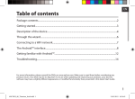
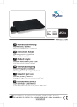
Artikel | Item | Article
Artikel | Articolo | Articulo
4507.1.00
4507GAz1_1404
GB Instruction Manual
TENS device - «Easy Free» TENS
Please read before using!
0483
Hydas GmbH & Co. KG | Hirzenhainer Straße 3 | 60435 Frankfurt, Germany
Tel.: +49 (0)69 / 95 40 61 10 | Fax: +49 (0)69 / 95 40 61 40 | e-Mail: [email protected]
www.hydas.de
Inhaltsverzeichnis
DEUTSCH
D
ENGLISH
GB
1 Introduction TENS........................................................................................................................................19
2 General description.....................................................................................................................................20
2.1 Content..................................................................................................................................................20
2.2 Description of the device...............................................................................................................20
2.3 Display indicators..............................................................................................................................20
3 Intended use..................................................................................................................................................20
3.1 Contraindications..............................................................................................................................21
4 Product description.....................................................................................................................................21
4.1 Technical data.....................................................................................................................................21
5 Important safety information.................................................................................................................22
6 Setup and operating procedures..........................................................................................................24
6.1 Function and use of buttons.........................................................................................................25
7 Program............................................................................................................................................................26
8 Operating instructions...............................................................................................................................27
8.1 Usage diagrams..................................................................................................................................27
9 Troubleshooting...........................................................................................................................................28
10 Maintenance..................................................................................................................................................29
11 Explanation of the symbols.....................................................................................................................29
12 Warranty..........................................................................................................................................................30
3
1 | Introduction of TENS
1. Theory of therapy
GB
Transcutaneous electrical nerve stimulation (TENS) is a non-invasive technique in which a low-voltage electrical current is delivered through wires
from a small power unit to electrodes located on the skin. Electrodes are
temporarily attached with paste in various patterns, depending on the specific condition and treatment goals. TENS is often used to treat pain, as an
alternative or addition to pain medications. Therapy sessions may last from
minutes to hours. The use of electrical stimulus for pain relief was popularized in the 19th century and became widespread in the 1960s and 1970s using
battery power.
Transcutaneous electrical nerve stimulation (TENS) was first introduced into
current clinical practice following Melzack and Wall‘s gate control theory of
pain in 1965. Davis (1993) and Lewith (1984) explain the gate control theory
of pain as follows. An area of the dorsal horn of the spinal cord, known as
the substantia gelatinosa, acts as a gate to nociceptive impulses. It receives
myelinated nerve fibres , the largest being A fibres, and small non-myelinated nerve fibres (C fibres). If pain impulses pass along fine myelinated fibres
and C fibres rather than along A fibres, the gate is opened, and the patient
perceives pain. If A fibre transmission of impulses is greater, the gate may
be closed.
There is also evidence that the TENS machine enhances the production of
the body‘s own natural pain killing substances: endorphins and encephalins.
Human body produces endorphins and encephalins, which are opiate-like
substances to counter the pain. Low frequency stimulation causes the release of the endorphins and encephalins.
2. Why consider digital pain relief?
Pain is a warning signal -we need these signals to tell us that something may
be wrong with our body. Without it, we may do not know that part of our body
might be damaged, thereby damaging them further. However, once we have
identified damage, pain serves little purpose. In the case of chronic, regular
pain it can significantly interfere with daily activities and the quality of life.
3. How does the Digital Pain Relief (TENS) work?
Digital Pain Relief (TENS) works by passing harmless electrical signals into the
body from its pads. This relieves pain in two ways:
19
1. It blocks the body‘s pain signals. These are normally transmitted from the
area of damage through the nerve fibers to the brain, TENS interrupts these
pain signals.
2. TENS stimulates the body‘s production of endorphins-its own natural
painkillers.
2
GB
1
2 | General description
2.1 | Contents
3
• Mainframe
• Wires
• Electrodes (Pads)
• Instruction book
5
• Batteries
2.2 | Description of the device
6
4
(Fig. 1)
1
2
3
4
5
6
7
Output plug
Output cable
Output plug socket
LCD Display
[ON]-Button = Switch on and Intensity (+)
[OFF]-Button = Switch off and Intensity (-)
[MODE/STOP]-Button = Function Selection
and Stop
2.3 | Display indicators
7
Fig.1
(Fig. 2)
Remaining Massage Time Display
9 Output Intensity Display
10 Function Display
11 Timer Display Punkt
8
8
11
9
3 | Intended use
Transcutaneous Electrical Nerve Stimulators are intended
for temporary relief of pain , including:
• Various chronic pain
• Various acute pain
20
10
Fig.2
3.1 | Contraindications
The device is safe for all people, with the following exceptions or the people
who are receiving physiotherapy:
GB
• People with acute disease
• Cancer patients
• People with infectious skin wounds
• Women who are in menstrual or expectant mothers
• People with heart disease
• People with high fever
• People with abnormal blood pressure
• People who have no feeling about their skins or people with abnormal skins
• People with abnormal feeling of their body except the abovge cases
4 | Product description
The AD-2011 is a battery operated pulse generator that sends electrical impulses through electrodes to the body and reaches the underlying nerves
and muscle.
• The device is provided with one controllable output channel.
• An electrode pair can be connected to the output channel.
The electronics of the AD-2011 Digital create electrical impulses whose
Intensity, Pulse Width, Pulse Rate may be altered according to the program.
Press buttons are very easy to use and the panel cover prevents changes in
the setting.
The AD-2011 corresponds to the below standards:
• IEC 60601-1: 2005/EN 60601-1:2006/AC:2010
(Medical electrical equipment -- Part 1: General requirements for basic safety
and essential performance).
• IEC60601-1-2:2007/EN 60601-1-2:2007/AC:2010
(Medical electrical equipment -- Part 1-2: General requirements for basic safety and essential performance - Collateral standard: Electromagnetic compatibility - Requirements and tests).
4.1 | Technical Data
Produkt name:
TENS Device
Model:
AD-2011 (item 4507)
21
GB
Number of treatment program:
8
Anzahl Intensities:
8
Range of pulse frequency:
2 ~ 150 Hz
Range of output voltage:
40 V ± 20% (500 Ohm load)
Classification:
Internally powered, Type BF applied
part, IPX0, No AP or APG, Continuous
operation
Machine size:
approx. 55 x 122 x 19 mm
Weight:
approx. 62 g (exclude batteries)
Power source:
Batteries: 2 x 1.5 V Type AAA
For operation
Environmental temperature:
5°C - 40°C
Environmental humidity:
< 80%
For storage and transport
Environmental temperature:
-20°C - 55°C
Environmental humidity:
≤ 95%
Environmental pressure:
80 KPa - 105 KPa
Battery life:
approx. 2 months with alkaline batteries
and 30 min. usage per day.
5 | Important safety hints
Retain the manual for
further use and forward
it to other users!
• Read all of the information in the operation guide and
any other literature in the box before operating the
unit.
• If there is any uncomfortable during using the device, please please stop
using it immediately and consult your doctor
• Turn off the power first before alternate the electrode pad to the other channel
22
GB
• Do not make sharp kinks in the connecting leads or electrodes.
• Do not use the device if you are connected to, or in the vicinity of,
high-frequency surgical or industrial equipment. This may cause burn
injuries on the skin under the electrodes, as well as problems with the
stimulator.
• Observe caution when using the device in the immediate vicinity of cellular
phones that are switched on.
• This device is not intended to be used unsupervised by children, individuals
with sensory deprivation of any kind or mentally challenged individuals. Any
users falling into these categories should be assisted by a responsible adult.
• Please don‘t use it in the bathroom or other place with high humidity.
• Please do not use it when driving, otherwise, it may lead to incident.
• Please do not use the device while in sleep.
• In the process of stimulating and therapy, please do not allow metal
parts of belts, wristwatches or necklaces touch the leaf electrode pads.
• Please don‘t use it for purposes other than outlined in this manual.
• The device might not meet its performance specifications or may cause
safety hazard if stored or used outside the specified temperature and
humidity ranges in specifications.
• Pregnant women should not use the device during the first trimester, and
should always consult a doctor, midwife or physiotherapist prior to use.
• Simultaneous connection of a PATIENT to a h.f. surgical EQUIPMENT may
result in burns at the site of the STIMULATOR electrodes and possible
damage to the STIMULATOR.
• Operation in close proximity (e.g. 1 m) to a shortwave or microwave therapy
equipment may produce instability in the device output.
• Application of electrodes near the thorax may increase the risk of cardiac
fibrillation.
• Please do not knock down, repair, and rebuild the device privately.
• Please do not use electrode pads other than those supplied by the
manufacturer, otherwise it may bring biocompatible hazard and might
result in measurement error.
• Please do not share the electrode pads with infective persons to avoid
cross-infection.
• The output wave parameters are not be influence by load resistance, except
output voltage. When the value of load resistance increased, the output
voltage will increase.
• Avoid strong magnetism interference, such as mobile telephone, microwave
oven, etc.
• Information regarding potential electromagnetic or other interference
between the device used and other devices together with advice regarding
23
GB
avoidance of such interference please see part ELECTROMAGNETIC
COMPATIBILITY INFORMATION. (p. 90)
• Never stick two adhesive gel pads to each other.
• Keep the adhesive gel pads clean and do not expose to heat or direct sunlight.
• If the gel pads do not attach or are dirty, wipe with a wet cloth or replace
with new ones.
• Do not clean the pad or adhesive gels with any chemical. Replacement pads
are available from your local distributor.
• Place the electrodes on intact skin only. Do not place on cuts or damaged
skin.
• The adhesive pads should be attached around the area of pain before
setting the stimulation mode and output intensity
6 | Setup and operating procedures
1. Insert batteries
a Open battery cover at the back of the device.
b Insert two „AAA“ size batteries. Please pay attention to polarity.
c Close the battery cover.
• Rechargeable batteries are not suitable for this device.
• Remove the batteries if the monitor will not be used for a month or
more to avoid relevant damage of battery leakage.
• Please do not mix use new and old batteries or different type of batteries.
• Please do not throw battery into fire.
• Avoid the battery fluid to get in your eyes. If it should get in your eyes,
immediately rinse with plenty of clean water and contact a physician.
2. How to place the adhesive gel pads on the electrode?
Each adhesive gel pad is protected by 2 layers of transparent film-one on
either side. Remove the layer of film and place that side of the gel pad to skin.
3. Attachment of electrode lead wires
a Insert the plug into the electrode socket on the main apparatus.
b Connect the snap-fasteners at the other end of the wire to the electrode
pads.
c Place the electrode on your body as directed by your physician.
• Clean the wires by wiping with a damp cloth.
• Coating them lightly with talcum powder will reduce tangling and
prolong life.
24
4. Finishing the operation
You should hold the plug when pulling it out. Please do not pull the wire.
• Please use clear water to wash or use wet cloth (instead of facial
tissue) to gently wipe up the electrodes when cleaning them.
• Wires stay away from babies and children, prevent the winding neck
causing suffocation and death.
GB
6.1 | Function and use of buttons [ON]-button:
• Press this button to turn on the unit and increase the output
intensity.
• Each time you press the [ON]-button the intensity of
stimulation will increase by one level. (0 - 8, 8 levels in total)
[OFF]-button:
• Press this button to turn off the unit and decrease the output
intensity.
• Each time you press the [OFF]-button the intensity of
stimulation will decrease by one level (8 - 0, 8 levels in total)
• The output intensity level will be displayed by the number on the LCD
display: «1» is the lowest, «8» is highest. The output strength will gradually
increase according to the selection of intensity level.
• If the output intensity is at «0», it means that the device is standby status
and will automatically shut off in 20 seconds.
• When the output intensity is at 1- 8, the time setting function starts to work.
The black spot on the LCD display will flash once each second.
• The adhesive pads should be attached around the area of pain before
setting the stimulation mode and output intensity.
[MODE/STOP]-button:
• To adjust the output function to a suitable level, press the
[MODE/STOP]-button
• There are 8 different selections of stimulation settings (form
A - H). For detailed descriptions please refer to the following
function chart.
The device has a memory function. Once a particular stimulation setting is chosen
it will remain on that setting even when the device is switched off and switched back
on. For example, if the device was set to «B» mode before being switched off, when
the device is restarted, it will remain in «B» mode until another mode is chosen.
25
• Press the [MODE/STOP]-button will change the stimulation setting from
one mode to another.
7 | Program
The changing process is as follows:
B
C
D
E
F
G
H
GB
A
Program
Function
A
Pain Relief
Tapping (Slow)
B
Pain Relief
Tapping (Fast)
C
Pain Relief
Vibrating (Slow)
D
Massage
Kneading (Slow)
E
Massage
Kneading (Fast)
F
Pain Relief/Massage
Vibrating (Fast)
Combined programs
G
Pain Relief/Massage course:
• recommended for shoulder and neck
A
E
C
B
F
E
F
A
15 min. / cycle
H
A Relief/Massage
E
C
B course:
F
E
F
A
Pain
F
D A
F
E
D A
F
• recommended for waist and back
15 min. / cycle
F
D
A
F
E
D
A
F
• When the device is turned on, even if the stimulation setting or intensity is
changed, it will not affect the timer which will continue to count down the
remaining time
• The device will turn off automatically when the set time has elapsed
• The set time of the device is 15 minutes.
• Recommended usage is 1-2 times a day with at least 2-3 hours of rest between
each use.
• If you feel any pain or discomfort during use,stop use immediately and
consult your doctor.
26
8 | Operating instructions
a Be sure you know the right points where to place the electrodes and affix
them there then, connect the electrodes to Digital Pain Relief with wire.
b Switch power on.
c After setting mode, intensity and time, you could feel stimulation at
GB
electrodes and treatment starts. The time display is enabled and displays
the remaining time of application.
d Switch power off.
e Take electrodes off and clear them as shown in «User Manual»
Clean the electrodes.
• You should hold the plug when pulling it out. Please do not pull the wire.
• Please use clear water to wash or use wet cloth (instead of facial tissue) to
gently wipe up the electrodes when cleaning them.
• Do not use brush or fingernail to clean surface of the electrodes to avoid
scratching them.
8.1 | Usage diagrams
Waist
Arm
Back
Joints
Leg
Adductors
Chest and
abdomen
Buttocks
27
GB
Shoulder
Foot
9 | Troubleshooting
The following table provides information on troubleshooting:
Malfunction
The reason
Countermeasure
You have no
feeling of
stimulus.
Are the batteries exhausted?
Replace the batteries.
Are the batteries
properly loaded?
Correctly load the
batteries.
Is the wire properly connected? Firmly connect the wire.
Stimulus is weak.
The skin
becomes red.
28
Have you removed the
transparent protection film
over the electrode pad?
Remove the transparent
protection film over the
electrode pad.
Do the electrode pads firmly
stick to the skin?
Firmly stick the electrode pad
to the skin.
Are the electrode pads
overlapped?
Separate the electrode pad
and stick them to the skin gain.
Are the electrode pads dirty?
Please clean the electrode
pad.
Is intensity too weak?
Turn the intensity regulation
dial to regulate it.
Are the electrode pads
properly positioned?
Change the position of the
electrode pad.
Is the therapeutic time too
long?
Control it within 10 - 15
minutes a time.
Do the electrode pads firmly
stick to the skin?
Please firmly stick the
electrode pad to the skin.
Are the electrode pads too
dry?
Please gently wipe them up
with wet cloth and then use
them again.
Are the electrode pads dirty?
Please clean the electrode
pad.
Are the surface of the
electrode pads scratched?
Please replace them with new
electrode pad.
Power sources cut
off in the therapeutic
process.
Have the electrode pads come Turn off the power and stick
off the skin?
the electrode pad firmly to
the skin.
Are the wires disconnected?
Turn off the power and
properly connect the wire.
Have the batteries been
exhausted?
Please replace them with new
ones.
GB
10 | Maintenance
• Do not drop this device subject it to strong impact.
• Avoid high temperature and direct sunlight. Do not immerse the device in
water.
• If this device is stored near freezing, allow it to acclimate to room
temperature before use.
• Do not attempt to disassemble this device.
• If you do not use the device for a long time, please remove the batteries...
• If the device becomes dirty, please clean it with a soft dry cloth. Do not use
any abrasive or volatile cleaners.
• No component can be maintained by user in the device.
The circuit diagrams, component part lists, descriptions, or other information
which will assist the user‘s appropriately qualified technical personnel to
repair those parts of equipment which are designated as repairable can be
supplied by the manufacturer.
• In order to ensure that the electrodes adhere as long as possible, they
should be cleaned carefully with a damp, lint-free cloth.
• After use, stick the electrodes onto the backing film.
• Electrode Pads are designed to be replaceable, so when the electrodes do
not adhere firmly, you must replace electrode-pads.
11 | Explanation of symbols
Symbol for «Consult Operation Guide»
Symbol for «WARNING!»
Symbol for «TYPE BF applied parts»
29
Environment Protection - Waste electrical products should not be disposed of with household waste. Please recycle where facilities exist.
Check with your local Authority or retailer for recycling advice.
Symbol for «Manufacturer»
GB
Symbol for «Date of manufacture»
Symbol for «Keep dry»
Symbol for »Serial number«
0483
Complies with 93/42/EEC requirements
12 | Warranty
The guarantee period is 24 months from the date of purchase and covers all
manufacturers’ errors in material and quality. This guarantee only applies if the
instructions for use have been followed and becomes ineffective if force has
been applied to the appliance or it has been used in any but the correct and
proper manner, or if it has been serviced by any unauthorised person.
Dear Customer,
In case you prodect does not function as you expected please do not reurn
immediately. Perhaps our hotline (+49-69-954061-24) can be of assistance
If you are still not satisfied, you have the possibility to return products under
40 € value free of charge within the BRD. We require your address. This you
may provide to the above listed telephonic Hotline or by e-mail to: technik@
hydas.de. Prepare the package for shipping and include the reciept and description of the problem. Please be aware of the fact that collect packages
may not be accepted.
Your Hydas customer service team
Warrenty and service:
Hydas GmbH & Co. KG
c/o atrikom fulfillment GmbH • Haagweg 12
65462 Ginsheim-Gustavsburg
Tel.: +49 69 - 95 40 61 13 • Fax: +49 69 - 95 40 61 40
e-Mail: [email protected] • http://www.hydas.de
30
EMC TABELLE - ELEKTROMAGNETISCHE KOMPATIBILITÄT
Leitlinien und Herstellererklärung zur elektromagnetischen Strahlung
Der Artikel 4508 ist für die Verwendung in einer Umgebung mit den nachstehend definierten elektromagnetischen Eigenschaften vorgesehen. Der Kunde oder der Benutzer
des Artikels hat sich zu vergewissern, dass er in einer solchen Umgebung eingesetzt wird.
Konformität
Elektromagnetische Umgebung - Anleitung
RF - Emissionen
CISPR 11
Emissionstest
Gruppe 1
Das 4508 verwendet RF-Energie ausschließlich für den internen Betrieb. Folglich sind
seine RF-Emissionen sehr schwach und es
besteht keine Gefahr, dass sie Interferenzen
mit einem danebenstehenden
Elektrogerät erzeugen.
Artikel 4508 ist für den Einsatz in allen Räumlichkeiten geeignet, inkl. Privaträumen und
an Orten, wo er direkt an das öffentliche Niederspannungs-Stromversorgungsnetz, das
Wohngebäude versorgt, angeschlossen wird.
RF Emissionen CISPR 11
Klasse B
Überschwingungsströme
IEC 61000-3-2
Nicht
zutreffend
Spannungsänderungen/
Spannungsschwankungen IEC 61000-3-3
Nicht
zutreffend
Für alle ME EQUIPMENT und ME SYSTEME
Leitlinien und Herstellererklärung zur elektromagnetischen Störfestigkeit
Der Artikel 4508 ist für die Verwendung in einer Umgebung mit den nachstehend definierten elektromagnetischen Eigenschaften vorgesehen. Der Kunde oder der Benutzer
des Artikels hat sich zu vergewissern, dass er in einer solchen Umgebung eingesetzt wird.
Funkstörfestigkeitstest
Leistungstest
IEC 60601
Compliance
level
Elektromagnetische
Umgebung - Empfehlungen
Entladung
statistischer
Elektrizität (ESD)
IEC 61000-4-2
± 6 kV Kontakt
± 8 kV Luftentladung
± 6 kV Kontakt
± 8 kV Luftentladung
Die Böden müssen aus Holz,
Beton oder Keramikfliesen
sein. Falls die Böden mit synthetischem Material ausgelegt
sind, muss die relative Feuchtigkeit bei einem Minimum
von 30% liegen.
Störfestigkeit
gegen schnelle
transiente
elektrische
Störgrößen
IEC 61000-4-4
± 2 kV für
Stromversorgungsleitungen
Nicht
zutreffend batteriebetriebenes
Gerät
Nicht zutreffend
Stoßspannungen
IEC 61000-4-5
± 1 kV line(s) to
line(s)
Nicht
zutreffend
Nicht zutreffend
Spannungseinbrüche,
Kurzzeitunterbrechungen und
Spannungsschwankungen
bei
ankommenden
Stromversorgungsleitungen
IEC 61000-4-11
<5% Ut
(Spannungseinbruch >95% Ut)
in 0.5 Zyklus
Nicht
zutreffend
Nicht zutreffend
3 A/m
Die elektromagnetischen
Felder mit der Spannung des
Stromnetzes müssen die
Pegeleigenschaften eines
durchschnittlichen Ortes in
einer typischen Büro- oder
Krankenhausumgebung
haben.
<40% Ut
(Spannungseinbruch >60% Ut)
in 5 Zyklen
< 70% Ut
(Spannungseinbruch > 30% Ut)
in 25 Zyklen
< 5% Ut
(Spannungseinbruch > 95% Ut)
in 5 Sekunden
Magnetfeld mit
energietechnischen
Frequenzen
(50/60 Hz)
IEC 61000-4-8
3 A/m
MERKE: UT ist die Spannung des Wechselstromnetzes vor Anwendung des Leistungstests.
Leitlinien und Herstellererklärung zur elektromagnetischen Strahlung
Der Artikel 4508 ist für die Verwendung in einer Umgebung mit den nachstehend definierten elektromagnetischen Eigenschaften vorgesehen. Der Kunde oder der Benutzer
des Artikels hat sich zu vergewissern, dass er in einer solchen Umgebung eingesetzt wird.
Funkstörfestigkeitstest
Leistungstest
IEC 60601
Richtwerte
Abgestrahlte
RF-Energie
IEC 61000-4-3
3 V/m
80 MHz bis 2.5
GHz
3 V/m
Elektromagnetische
Umgebung - Empfehlungen
Tragbare und mobile RF-Kommunikationsgeräte dürfen nur in einem
Abstand zum Gerät und seinem
Zubehör benutzt werden, der mindestens dem empfohlenen und mit
der Formel für die Senderfrequenz
berechneten Abstand entspricht.
Empfohlener Abstand:
80 MHz to 800 MHz
800 MHz to 2,5 GHz
Wonach P der Leistungspegel der
Maximalspannung des Senders in
Watt (W) ist, der in den
technischen Spezifikationen des
Herstellers angegeben ist, und
demzufolge d der empfohlene
Abstand in Metern (m).
Die Feldstärke der festen RF-Sender,
wie durch eine elektromagnetische
Untersuchunga festgelegt, muss
unter dem Richtwert liegen, der in
jeder Frequenzbandbreiteb
liegt.
Störsignale können in der Nähe
jedes Gerätes mit dem folgenden
Symbol auftreten:
ANMERKUNG 1: Von 80 MHz bis 800 MHz wird die Hochfrequenzamplitude verwendet.
ANMERKUNG 2: Diese Richtwerte können in bestimmten Situationen nicht angemessen
sein. Die elektromagnetische Ausbreitung wird durch Absorption und Reflexion von
Gebäuden, Gegenständen und Menschen beeinflusst.
a
: Die Feldstärken der Signale aus festen Sendern, wie Basisstationen eines Funktelefons
(Mobil-oder schnurloses Telefon) und eines mobilen Radios, Amateurfunkradios,
AM- und FM-Radio-und TV-Signalen, sind nicht exakt vorherzubestimmen. Eine Analyse
der elektromagnetischen Umgebung des Ortes ist zu erwägen, um die elektromagnetische Umgebung, die von festen RF-Sendern ausgeht, berechnen zu können. Wenn die
Stärke des in der Umgebung des Compex Performance gemessenen Feldes den oben
angegebenen RF-Richtwert überschreitet, ist die korrekte Funktionsweise des Compex
Performance zu überprüfen.
b
: Oberhalb der Frequenzamplitude von 150 kHz bis 80 MHz muss die Feldstärke
weniger als 3 V/m betragen.
Empfohlener Abstand zwischen einem tragbaren und mobilen
RF Telekommunikationsgerät und dem 4508.
Das 4508 wurde für eine elektromagnetische Umgebung entwickelt, in der ausgestrahlte RF-Turbulenzen kontrolliert werden. Käufer oder Benutzer des 4508 können
zur Verhütung elektromagnetischer Störsignale beitragen, indem sie den in der nachfolgenden Tabelle mit den empfohlenen Richtwerten angegebenen Mindestabstand
zwischen den tragbaren und mobilen RF-Kommunikationsgeräten (Sender) und
dem 4508 und die maximale elektrische Leistung des Telekommunikationsgeräts
berücksichtigen.
Max. elektrische
Leistung des
Senders
W
Abstand gemäß Frequenz des Senders mCISPR 11
150 kHz bis 80 MHz
d = 1,2√P
80 MHz bis 800 MHz
d = 1,2√P
800 MHz bis 2,5 GHz
d = 2,3√P
0,01
0.12
0.12
0.23
0,1
0.38
0.38
0.73
1
1.2
1.2
2.3
10
3.8
3.8
7.3
100
12
12
23
Falls die maximale elektrische Leistung eines Senders nicht in der nachstehenden
Tabelle aufgeführt ist, kann der empfohlene Mindestabstand in Metern (m) mit der
Formel für die Senderfrequenz berechnet werden. wonach P dem vom Hersteller
angegebenen maximalen elektronischen Leistungspegel des Senders in Watt (W)
entspricht.
ANMERKUNG 1: Von 80 MHz bis 800 MHz wird die Hochfrequenzamplitude verwendet.
ANMERKUNG 2: Diese Richtwerte können in bestimmten Situationen nicht angemessen
sein. Die elektromagnetische Übertragung wird durch Absorption und Reflexion von
Gebäuden, Gegenständen und Personen verändert.
ELECTROMAGNETIC COMPATIBILITY INFORMATION
For all ME EQUIPMENT and ME SYSTEMS
Guidance and manufacture’s declaration - electromagnetic emissions
The 4508 is intended for use in the electromagnetic environment specified below.
The customer or the user of the 4508 should assure that it is used in such an environment.
Compliance
Electromagnetic
environment-guidance
RF emissions
CISPR 11
Group 1
The 4508 uses RF energy only for its internal function. Therefore, its RF
emissions are very low and are not likely to
cause any interference in nearby electronic equipment
RF emissions CISPR 11
Class B
Emissions test
Harmonic emissions
IEC 61000-3-2
Not
applicable
Voltage fluctuations/
flicker emissions IEC
61000-3-3
Not
applicable
The 4508 is suitable for use in all
establishments other than domestic and
those directly connected to the public
low-voltage power supply network that
supplies buildings
used for domestic purposes.
For all ME EQUIPMENT and ME SYSTEMS
Guidance and manufacturer’s declaration - electromagnetic immunity
The 4508 is intended for use in the electromagnetic environment specified below.
The customer or the user of the 4508 should assure that it is used in such an environment.
IMMUNITY test
IEC 60601 test
level
Compliance
level
Electromagnetic
environment-guidance
Electrostatic
discharge (ESD)
IEC 61000-4-2
± 6 kV contact
± 8 kV air
± 6 kV contact
± 8 kV air
Floors should be wood,
concrete or ceramic tile. If
floors are covered with
synthetic material, the relative
humidity should be at least
30 %.
Electrical fast
transient/burst
IEC 61000-4-4
±2 kV for power
supply lines
not applicable
not applicable
(For INTERNALLY POWERED
ME EQUIPMENT)
Surge
IEC 61000-4-5
± 1 kV line(s) to
line(s)
not applicable
not applicable
(For INTERNALLY POWERED
ME EQUIPMENT)
Voltage dips,
short interruptions and
voltage variations
on power supply
input lines
IEC 61000-4-11
<5% UT
(>95% dip in
UT) for 0.5 cycle
not applicable
not applicable
(For INTERNALLY POWERED
ME EQUIPMENT)
3 A/m
Power frequency magnetic
fields should be at levels characteristic of a typical location
in a typical commercial or
hospital environment.
40% UT
(60% dip in UT)
for 5 cycles
70% UT
(30% dip in UT)
for 25 cycles
<5% UT
(>95% dip in
UT) for 5 sec
Power frequency
(50Hz/60Hz)
magnetic field
IEC 61000-4-8
3 A/m
NOTE: UT is the a.c. mains voltage prior to application of the test level.
For ME EQUIPMENT and ME SYSTEMS that are not LIFE-SUPPORTING
Guidance and manufacturer‘s declaration - electromagnetic immunity
The 4508 is intended for use in the electromagnetic environment specified below.
The customer or the user of the 4508 should assure that it is used in such an environment.
IMMUNITY test
IEC 60601 test Compliance
level
level
Radiated RF
IEC 61000-4-3
3 V/m 80 MHz
to 2.5 GHz
3 V/m
Electromagnetic
environment-guidance
Portable and mobile RF communications equipment should be
used no closer to any part of the
4508, including cables, than the
recommended separation distance
calculated from the equation
applicable to the frequency of the
transmitter. Recommended separation distance:
80 MHz to 800 MHz
800 MHz to 2,5 GHz
Where P is the maximum output
power rating of the transmitter in
watts (W) according to the transmitter manufacturer and d is the
recommended separation distance
in meters (m).
Field strengths from fixed RF
transmitters, as determined by an
electromagnetic site survey,a should
be less than the compliance level in
each frequency range.b
Interference may occur in the
vicinity of equipment.
Marked with the following symbol:
NOTE 1 At 80 MHz and 800 MHz, the higher frequency range applies.
NOTE 2 These guidelines may not apply in all situations. Electromagnetic propagation
is affected by absorption and reflection from structures, objects and people.
a
: Field strengths from fixed transmitters, such as base stations for radio (cellular/cordless) telephones and land mobile radios, amateur radio, AM and FM radio broadcast
and TV broadcast cannot be predicted theoretically with accuracy. To assess the electromagnetic environment due to fixed RF transmitters, an electromagnetic site survey
should be considered. If the measured field strength in the location in which the
4508 is used exceeds the applicable RF compliance level above, the 4508 should be
observed to verify normal operation. If abnormal performance is observed, additional
measures may be necessary, such as re-orienting or relocating the 4508.
b
: Over the frequency range 150 kHz to 80 MHz, field strengths should be less than
[V1] V/m.
For ME EQUIPMENT and ME SYSTEMS that are not LIFE-SUPPORTING
Recommended separation distances between
portable and mobile RF communications equipment and the 4508
The 4508 is intended for use in an electromagnetic environment in which radiated RF
disturbances are controlled. The customer or the user of the 4508 can help prevent
electromagnetic interference by maintaining a minimum distance between portable
and mobile RF communications equipment (transmitters) and the 4508 as recommended below, according to the maximum output power of the communications
equipment.
Rated maximum
output power of
transmitter
W
Separation distance according to frequency of transmitter
m
150 kHz to 80 MHz
d = 1,2√P
80 MHz to 800 MHz
d = 1,2√P
800 MHz to 2,5 GHz
d = 2,3√P
0,01
0.12
0.12
0.23
0,1
0.38
0.38
0.73
1
1.2
1.2
2.3
10
3.8
3.8
7.3
100
12
12
23
For transmitters rated at a maximum output power not listed above, the
recommended separation distance d in meters (m) can be determined using the
equation applicable to the frequency of the transmitter, where P is the maximum
output power rating of the transmitter in watts (W) according to the transmitter
manufacturer.
NOTE 1 At 80 MHz and 800 MHz, the separation distance for the higher frequency
range applies.
NOTE 2 These guidelines may not apply in all situations. Electromagnetic propagation is affected by absorption and reflection from structures, objects and people.
HERSTELLER
Hydas GmbH & Co.KG
Hirzenhainer Straße 3,
60435 Frankfurt/M., Germany
Tel.:069/9540610,
Fax: 069/95406140
e-mail: [email protected]
GARANTIE & SERVICE
Hydas GmbH & Co. KG
c/o atrikom fulfillment GmbH
Haagweg 12
65462 Ginsheim-Gustavsburg
OFFICE USA
Hydas Inc.
P.O. Box 420, Hershey, PA. 17033
Tel. 717-533-5583
Fax 717-533-5548
Warehouse: 1810 Church Rd.,
Hummelstown, PA. 17036 U.S.A.
e-mail: [email protected]