1
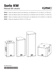
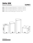
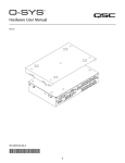
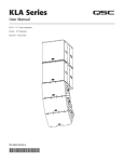
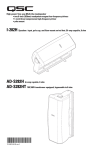
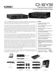
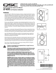
KW Series SUS KIT 122
User Manual
Contents:
Pull Back Bar, KW122 – 1 each
M10 Eyebolt – 3 each
KW122 Pull Back Gasket – 1 each
M10 Nut – 1 each
Contents:
M10 Lock Washer – 1 each
M10 Flat Washer – 2 each
M10 Button Head, Hex Socket, Screw – 1 each
Instruction Sheet, KW SUS KIT 122 – 1 each
This suspension kit is required for horizontal suspension of the QSC KW122 Loudspeaker System. This kit can also be used to suspend the KW122,
KW152 or KW153 Loudspeaker Systems vertically, and the KW152 and KW153 horizontally. All loudspeaker systems must be suspended from a
solid structure.
This kit contains hardware to suspend one loudspeaker system.
IMPORTANT SAFETY PRECAUTIONS AND EXPLANATION OF SYMBOLS
WARNING!
Install in accordance with QSC Audio Product’s instructions and under the supervision of a licensed Professional Engineer.
Before placing, installing, rigging, or suspending any speaker product, inspect all hardware, suspension, enclosures, transducers, brackets
and associated equipment for damage. Any missing, corroded, deformed, or non-load rated component could significantly reduce the
strength of the installation or placement. Correct any such condition immediately so as not to severely reduce the safety of the installation.
Use only properly rated hardware for the loading conditions of the installation, and any possible short-term, unexpected overloading.
Never exceed the rating of the hardware or equipment.
Consult a licensed, Professional Engineer regarding physical equipment installation. Ensure you understand and adhere to all local, state
and national regulations regarding the safety and operation of equipment.
Use only load-rated hardware to attach to the eyebolts or Pull Back Bar when suspending these products.
Do not suspend these products from any structural element on the loudspeaker enclosure other than the load rated M10 suspension
points as described in this document.
Use proper lifting techniques / technologies.
Safety Precautions and Explanation of Terms and Symbols
WARNING! The term “WARNING!” indicates instructions regarding personal safety. If the instructions are not followed the result may be bodily
injury or death.
CAUTION! The term “CAUTION!” indicates instructions regarding possible damage to physical equipment. If these instructions are not followed, it
may result in damage to the equipment that may not be covered under the warranty.
IMPORTANT! The term “IMPORTANT!” indicates instructions that are vital to the successful completion of the operation.
NOTE: The term NOTE is used to indicate additional useful information.
The exclamation point within an equilateral triangle is intended to alert the user to the presence of important operation and maintenance (servicing) instructions in this manual.
The intent of the lightning flash with arrowhead symbol in a triangle is to alert the user to the presence of un-insulated “dangerous”
voltage within the product’s enclosure that may be of sufficient magnitude to constitute a risk of electric shock to humans.
Weight (Net)
KW122
49 lbs (22.2 kg)
KW152
62 lbs (28.1 kg)
KW153
87 lbs (39.5 kg)
Warranty (USA only; other countries, see your dealer or distributor)
Disclaimer
QSC Audio Products, LLC is not liable for any damage to amplifiers or any other equipment that is caused by negligence or improper installation and/
or use of this loudspeaker product.
QSC Audio Products 3-Year Limited Warranty
QSC Audio Products, LLC (”QSC”) guarantees its products to be free from defective material and/or workmanship and will replace defective parts and
repair malfunctioning products under this warranty when the defect occurs under normal installation and use-provided the unit is returned to our factory,
one of our authorized service stations or an authorized QSC International Distributor via pre-paid transportation with a copy of proof of purchase (i.e.,
sales receipt). This warranty provides that the examination of the return product must indicate, in our judgment, a manufacturing defect. This warranty
does not extend to any product which has been subjected to misuse, neglect, accident, improper installation, or where the date code has been removed
or defaced. QSC shall not be liable for incidental and/or consequential damages. This warranty gives you specific legal rights. This limited warranty is
freely transferable during the term of the warranty period. The warranty on QSC products is NOT VALID if the products have been purchased from an
unauthorized dealer/online e-tailer, or if the original factory serial number has been removed, defaced, or replaced in any way. Damage to, or loss of any
software or data residing on the product is not covered. When providing repair or replacement service, QSC will use reasonable efforts to reinstall the
product’s original software configuration and subsequent update releases, but will not provide any recovery or transfer of software or data contained on
the serviced unit not originally included in the product.
Customers may have additional rights, which vary from state to state or from country to country. In the event that a provision of this limited warranty is
void, prohibited or superseded by local laws, the remaining provisions shall remain in effect.
Periodically, this warranty is updated. To obtain the most recent version of QSC’s warranty statement, please visit www.qscaudio.com.
Contact us at 800-854-4079 or visit our website at www.qscaudio.com.
The QSC limited warranty is valid for a period of three (3) years from date of purchase in the United States and many (but not all)
other countries.
For QSC warranty information in countries other than the United States, contact your authorized QSC international distributor. A list of QSC International
distributors is available at www.qscaudio.com.
To register your QSC product online, go to www.qscaudio.com and select ”Product Registration”. Other questions regarding this warranty can be answered by calling, e-mailing or contacting your authorized QSC distributor.
© 2010, QSC Audio Products, LLC.
Patents may apply or be pending.
QSC is a registered trademark of QSC Audio Products, LLC.
“QSC” and the QSC logo are registered with the U.S. Patent and Trademark Office.
All trademarks are the property of their respective owners.
1
KW122 Loudspeaker System
2
The KW122 Loudspeaker System can be suspended in both vertically and horizontally. The horizontal
orientation allows you to suspend the loudspeaker with the LF Driver to the left or right, and requires the
installation of a Pull Back Bar.
Vertical Suspension
Tools Required:
• 6 mm Hex Wrench (Allen Wrench)
Parts Required:
• M10 Eyebolt – (3)
Install Two Top-surface Eyebolts (Figure 1)
3
1. Use a 6 mm hex wrench to remove the factory-installed M10 flat-head screws from the top of the
loudspeaker enclosure.
– Figure 1 –
2. Thread an eyebolt into the two threaded inserts on the top of the loudspeaker enclosure. Do not use washers.
3. Tighten the eyebolts until their shoulders are snug against the enclosure. Continue to rotate the eyebolts until they reach the desired position.
Install One Pull Back Eyebolt (Figure 1)
1. Use a 6 mm hex wrench to remove the M10 flat-head screw located at the rear of the enclosure just below the amplifier module.
2. Thread an eyebolt into the threaded insert just below the amplifier module. Do not use a washer.
3. Tighten the eyebolt until the shoulder is snug against the enclosure. Continue to rotate the eyebolt until it reaches the desired position.
Important: Do not use any washers or the Pull Back Bar when vertically suspending the KW122 loudspeaker.
1
Horizontal Suspension (Figure 2)
1
1
When suspending the KW122 in a horizontal position you must install the Pull Back Bar
and two eyebolts in one of the side panels.
Tools Required:
• 6 mm Hex Wrench (Allen Wrench)
• 7 mm Open End / Box End Wrench
Parts Required:
• Pull Back Bar, KW122 – (1)
• M10 Eyebolt – (3)
• KW122 Pull Back Gasket – (1)
• M10 Nut – (1)
• M10 Lock Washer – (2)
• M10 Flat Washer – (2)
• M10 Button Head, Hex Socket, Screw – (1)
3
2
2
Horizontal Suspension (Figure 2)
The Pull Back Bar attaches to the same M10 installation location, as shown, regardless of
which side the LF Driver is on.
NOTE: If you are suspending the KW122 in the direction opposite of what is shown:
• The Pull Back Bar is installed in the same place as shown.
•
•
The Eyebolt is installed in the as shown in the alternate installation (Figure 3).
The two “top” Eyebolts are installed in the same positions, but on the other side of
the enclosure. (Figure 2).
1. Remove the factory installed M10 flat-head screw from the side of the enclosure to which
the Pull Back Bar is to be attached.
3
– Figure 2 –
2. Test fit the Pull Back Bar, attachment, washers, and gaskets to ensure proper assembly prior
to sticking self-adhesive gasket to Pull Back Bar.
3. Attach the Pull Back Gasket to the Pull Back Bar by peeling off the adhesive backing and
pressing the adhesive side to one end of the Pull Back Bar. Ensure that the hole in the
gasket aligns with the hole in the Pull Back Bar.
4. Install one M10 Lock Washer, then one M10 Flat Washer, onto the M10 Hex Socket, Buttonhead screw.
5. Insert the screw into the Pull Back Bar through the hole with the gasket, from the opposite
side of the Pull Back Bar from the gasket. (The gasket goes between the Pull Back Bar and
the loudspeaker enclosure.
6. Using a 6 mm hex wrench, bolt the Pull Back Bar to the enclosure with the screw and two
washers. Before tightening fully, ensure the Pull Back Bar is perpendicular to the edge of the
enclosure. Tighten the screw until the split lock washer is flattened.
– Figure 3 –
7. Insert the eyebolt into the Pull Back Bar. The “eye” of the eyebolt must be oriented toward
the two “top” eyebolts installed in the enclosure. Attach the eyebolt to the Pull Back Bar
with hex nut, lock washer, and flat washer. Tighten until the split lock washer is flattened.
Install Two Top-surface Eyebolts (Figure 2)
1. Use a 6 mm hex wrench to remove the two factory-installed M10 flat-head screws from the side (top) of the loudspeaker enclosure. This side
becomes the top.
2. Thread one eyebolt into each of the two threaded inserts on the top side of the loudspeaker enclosure. Do not use washers.
3. Tighten the eyebolts until their shoulders are snug against the enclosure. Continue to rotate the eyebolts until they reach the desired position.
2
KW152 and KW153 Loudspeaker System
The KW152 and KW153 can be suspended vertically with the LF Driver on the top or bottom. The following instructions apply to either orientation.
Vertical Suspension
2
Tools Required:
• 6 mm Hex Wrench (Allen Wrench)
Parts Required:
• M10 Eyebolt – (3)
1
Install Two Top-surface Eyebolts (Figure 4)
4
1. Use a 6 mm hex wrench to remove the two factory-installed M10 flat-head screws from the
top of the loudspeaker enclosure.
2. Thread one eyebolt into each of the two threaded inserts on the top of the loudspeaker
enclosure. Do not use washers.
3. Tighten the eyebolts until their shoulders are snug against the enclosure. Continue to rotate
the eyebolts until they reach the desired position. back eyebolt.
3
– Figure 4 –
Install One Pull Back Eyebolt
1. Using a 6 mm hex wrench, remove the M10 flat head screw located at the rear of the enclosure, just below the amplifier module.
NOTE: You can optionally use the threaded insert just above the amplifier module for the pull back eyebolt.
2. Thread an eyebolt into the enclosure’s threaded insert; do not use a flat washer or standoff on the pull back eyebolt.
3. Tighten the eyebolt until the shoulder is snug against the enclosure. Continue to rotate the eyebolt until it reaches the desired position.
Horizontal Suspension
Tools Required:
• 6 mm Hex Wrench (Allen Wrench)
Parts Required:
• M10 Eyebolt – (3)
Install Two Top-surface Eyebolts (Figure 5)
1. Use a 6 mm hex wrench to remove the two factory-installed M10 flat-head screws from
the side (top) of the loudspeaker enclosure. This side becomes the top.
2
2. Thread one eyebolt into each of the two threaded inserts on the top side of the
loudspeaker enclosure. Do not use washers.
3. Tighten the eyebolts until their shoulders are snug against the enclosure. Continue to
rotate the eyebolts until they reach the desired position.
3
Install One Pull Back Eyebolt
1
1. Use a 6 mm hex wrench to remove the M10 flat head screw located at the rear of the
enclosure just above the amplifier module.
2. Thread an eyebolt into the threaded insert. Do not use washers.
3. Tighten the eyebolt until the shoulder is snug against the enclosure. Continue to rotate
the eyebolt until it reaches the desired position.
© 2010 QSC Audio Products, LLC. All rights reserved. QSC and the QSC logo are registered trademarks of
QSC Audio Products, LLC in the U.S. Patent and Trademark office and other countries. Tilt-Direct, DMT, Intrinsic
Correction, DEEP and GuardRail are all trademarks of QSC Audio Products, LLC. All other trademarks are the
property of their respective owners. Patents may apply or be pending.
– Figure 5 –
TD-000318-00 A
*TD-000318-00*