1
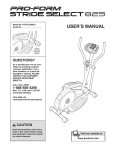
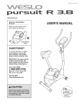
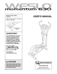
Model No. WLTL01806.0
Serial No.
USER’S MANUAL
Serial Number
Decal
QUESTIONS?
As a manufacturer, we are committed to providing complete
customer satisfaction. If you
have questions, or if parts are
damaged or missing, PLEASE
CONTACT OUR CUSTOMER
SERVICE DEPARTMENT
DIRECTLY.
CALL TOLL-FREE:
1-866-699-3756
Mon.–Fri., 6 a.m.–6 p.m. MST
ON THE WEB:
www.wesloservice.com
CAUTION
Read all precautions and instructions in this manual before using
this equipment. Save this manual
for future reference.
Visit our website at
www.weslo.com
new products, prizes,
fitness tips, and much more!
TABLE OF CONTENTS
IMPORTANT PRECAUTIONS . . . . . . . . . . . . . . . . . . . . . . . . . . . . . . . . . . . . . . . . . . . . . . . . . . . . . . . . . . . . . . . . 2
BEFORE YOU BEGIN . . . . . . . . . . . . . . . . . . . . . . . . . . . . . . . . . . . . . . . . . . . . . . . . . . . . . . . . . . . . . . . . . . . . . . 3
ASSEMBLY . . . . . . . . . . . . . . . . . . . . . . . . . . . . . . . . . . . . . . . . . . . . . . . . . . . . . . . . . . . . . . . . . . . . . . . . . . . . . . 4
TREADMILL OPERATION . . . . . . . . . . . . . . . . . . . . . . . . . . . . . . . . . . . . . . . . . . . . . . . . . . . . . . . . . . . . . . . . . . . 8
MAINTENANCE AND TROUBLESHOOTING . . . . . . . . . . . . . . . . . . . . . . . . . . . . . . . . . . . . . . . . . . . . . . . . . . . 11
CONDITIONING GUIDELINES . . . . . . . . . . . . . . . . . . . . . . . . . . . . . . . . . . . . . . . . . . . . . . . . . . . . . . . . . . . . . . 12
PART LIST . . . . . . . . . . . . . . . . . . . . . . . . . . . . . . . . . . . . . . . . . . . . . . . . . . . . . . . . . . . . . . . . . . . . . . . . . . . . . . 14
EXPLODED DRAWING . . . . . . . . . . . . . . . . . . . . . . . . . . . . . . . . . . . . . . . . . . . . . . . . . . . . . . . . . . . . . . . . . . . . 15
ORDERING REPLACEMENT PARTS . . . . . . . . . . . . . . . . . . . . . . . . . . . . . . . . . . . . . . . . . . . . . . . . . Back Cover
LIMITED WARRANTY . . . . . . . . . . . . . . . . . . . . . . . . . . . . . . . . . . . . . . . . . . . . . . . . . . . . . . . . . . . . . . Back Cover
IMPORTANT PRECAUTIONS
WARNING:
To reduce the risk of serious injury, read the following important precautions
before using the treadmill.
1. It is the responsibility of the owner to ensure
that all users of the treadmill are adequately
informed of all warnings and precautions.
9. Wear appropriate clothes while using the
treadmill. Do not wear loose clothes that could
become caught on the treadmill.
2. Use the treadmill only as described.
10. Wear athletic shoes while using the treadmill;
do not use the treadmill with bare feet, wearing only stockings, or in sandals.
3. This treadmill is intended for in-home use
only. Do not use the treadmill in a commercial, rental, or institutional setting.
11. Do not use the treadmill if it is not working
properly.
4. Place the treadmill on a level surface, with
eight feet of clearance behind it. Place a mat
under the treadmill to protect the floor.
12. Do not place your hands or feet under the
treadmill while it is in use.
5. Inspect and properly tighten all parts of the
treadmill regularly; replace any worn parts
immediately.
13. Always hold the handrail when mounting,
dismounting, or exercising on the treadmill.
14. If you feel pain or dizziness while exercising,
stop immediately and begin cooling down.
6. The roller guards must be 1/8 inch from the
rear roller (see the drawing on page 3). Adjust
the roller guards, if necessary.
15. Warning and caution decals have been placed
on the treadmill in the locations shown on
page 3. If a decal is missing or illegible, call
the toll-free telephone number on the front
cover of this manual and order a free replacement decal. Apply the decal in the location
shown.
7. Keep children under the age of 12 and pets
away from the treadmill at all times.
8. The treadmill should not be used by persons
weighing over 250 pounds. Never allow more
than one person on the treadmill at a time.
WARNING:
Before beginning this or any exercise program, consult your physician. This
is especially important for persons over the age of 35 or persons with pre-existing health problems.
Read all instructions before using this product. ICON assumes no responsibility for personal injury
or property damage sustained by or through the use of this product.
2
BEFORE YOU BEGIN
Thank you for selecting the new WESLO®
CARDIOPACER 2.0 treadmill. The CARDIOPACER
2.0 treadmill is designed to let you enjoy effective cardiovascular workouts in the comfort and convenience
of your home. And when the CARDIOPACER 2.0
treadmill is not in use, it can be folded up, requiring
less than half the space of other treadmills.
number and serial number before calling. The model
number of the treadmill is WLTL01806.0. The serial
number can be found on a decal attached to the treadmill (see the front cover of this manual for the location).
To avoid a registration fee for any service needed
under warranty, you must register the treadmill at
www.wesloservice.com/registration.
For your benefit, read this manual carefully before
using the treadmill. If you have questions after reading this manual, please see the front cover of this
manual. To help us assist you, note the product model
Before reading further, please review the drawing
below and familiarize yourself with the labeled parts.
Console
Handrail
Latch Pin
Caution Decal
(one on each side)
Walking Belt
Roller Guards
Frame Pin
Warning Decal
Rear Roller Bolts
3
ASSEMBLY
Assembly requires two persons. Set the treadmill in a cleared area and remove all packing materials. Do not
dispose of the packing materials until assembly is completed.
Assembly requires the included tools and your own rubber mallet
.
Use the drawings below to identify the hardware used during assembly. Note: If a part is not in the parts bag,
check to see if it has been preattached to one of the parts to be assembled. To avoid damaging plastic
parts, do not use power tools for assembly.
M6 x 15mm
Screw (4)–2
M10 x 50mm Screw (15)–2
M10 Washer
(14)–10
M10 x 55mm Screw (13)–4
M12 Washer
(12)–2
M12 x 60mm Screw (11)–2
M10 Nut (18)–10
1. Attach the Base Crossbar (44) to the two
Upright Bases (16) with two M10 x 50mm
Screws (15) and two 10mm Washers (14) as
shown.
1
16
15
14
44
16
14
15
4
2. Identify the Left Upright (3), which has the
Upright Wire (46) inside. Orient the Left Upright
as shown, and attach it to the left Upright Base
(16) with two M10 x 55mm Screws (13), four
M10 Washers (14), and two M10 Nuts (18). Do
not tighten the Nuts yet.
2
46
Attach the Right Upright (9) to the right Upright
Base (16) in the same way. Do not tighten the
Nuts yet.
3
13
13
9
14
14
13
13
14
18
14
14
16
14
16
18
3. Slide the ends of the Handrail (5) into the tubes
on the Left and Right Uprights (3, 9). If necessary, use a rubber mallet to fully insert the
Handrail. Attach the Handrail with two M6 x
15mm Screws (4).
3
4
49
Connect the Upright Wire (46) to the Handrail
Wire (49).
46
5
3
4
9
5
4. Position the Frame (41) between the Left and
Right Uprights (3, 9). Attach the Frame to the
Uprights with two M12 x 60mm Screws (11) and
two 12mm Washers (12).
4
3
12
46 23
9
11
Connect the Upright Wire (46) in the Left Upright
(3) to the wire from the Reed Switch (23).
See step 2. Tighten the four M10 Nuts (18)
used in step 2.
12
11
18
41
5. The Console (10) requires one “AA” battery (not
included); an alkaline battery is recommended.
Remove the battery cover (not shown) and insert
a battery; make sure that the negative (–) end
of the battery is touching the spring in the
Console. Then, reattach the battery cover.
5
10
“AA”
Battery
Slide the Console (10) onto the bracket in the
center of the Handrail (5).
Bracket
Connect the Handrail Wire (49) to the console
wire. Then, insert the excess wiring into the
Handrail (5) and press the Grommet (48) into
the hole in the Handrail.
5
48
49
6. Remove the knob from the pin. Insert the pin,
with the spring, into the Latch Assembly (7) as
shown. Then, tighten the knob onto the pin.
6
7
Knob
Pin
Spring
6
7. Insert the Frame Pin (45) through the Right
Upright (9) into the hole in the Frame (41).
7
Hole
9
41
45
8. Make sure that all parts are properly tightened before you use the treadmill. To protect the floor or carpet,
place a mat under the treadmill.
7
TREADMILL OPERATION
LUBRICATING THE WALKING PLATFORM
The console features five modes:
Before the treadmill is used, the walking platform
should be lubricated. Open the included lubricant
packet. Reach under one side of the walking belt as
far as you can, and apply half of the lubricant to the
walking platform. Then, reach under the other side of
the walking belt and apply the remaining lubricant.
After you have applied the lubricant, walk on the
treadmill for a few minutes to spread the lubricant.
• Scan—This mode displays the Time, Speed,
Distance, and Calories modes.
• Time—This mode displays the elapsed time.
• Speed—This mode displays your speed, in miles
per hour.
• Distance—This mode displays the number of miles
you have walked.
• Calories—This mode displays the approximate
number of calories you have burned.
Apply
lubricant
here
Note: The console can display speed and distance in
either miles or kilometers. An “M” for miles or a “K” for
kilometers will appear in the right side of the display
while the Speed or Distance mode is displayed. Press
the Mode button for about six seconds to change the
unit of measurement if desired.
Apply
lubricant
here
Follow the steps below to operate the console.
1. Turn on the console.
To turn on the console, press the Mode button or
begin walking. Note: If a battery was just installed,
the console will already be on.
STEP-BY-STEP CONSOLE OPERATION
Before the console can be operated, a battery must be
inserted (see assembly step 5 on page 6). If there is a
sheet of clear plastic on the console, peel off the
plastic.
2. Track your progress with the five modes.
When the power is
turned on, the
Scan mode will be
selected and the
word SCAN will
appear in the display. The console
will display the
Time, Speed,
Distance, and
Calories modes, for several seconds each, in a
repeating cycle.
To select only the Time, Speed, Distance, or
Calories mode, press the Mode button until only the
Time, Speed, Distance, or Calories arrow appears
in the display. Make sure that the word SCAN does
not appear.
To reset all modes, press the Mode button for about
three seconds.
8
3. Turn off the console.
3. Insert the frame
3
Right
pin through the
Upright
lower end of the
right upright into
the hole in the
frame. To protect
the floor or carpet
from damage,
place a mat under
Frame Pin
the treadmill.
Keep the treadmill out of direct
sunlight. Do not leave the treadmill in the storage position in temperatures above 85°
Fahrenheit.
To turn off the console, simple wait for a few minutes. If the walking belt is not moved and the console button is not pressed for a few minutes, the
console will turn off automatically.
HOW TO FOLD THE TREADMILL FOR STORAGE
When the treadmill is not in use, it can be folded to
the compact storage position. CAUTION: You must
be able to safely lift 25 pounds (11 kg) to raise,
lower, or move the treadmill.
1. See drawing 1a below. Remove the frame pin. See
drawing 1b. Hold the treadmill frame with both
hands. CAUTION: To decrease the possibility of
injury, bend your legs and keep your back
straight. As you raise the frame, make sure to
lift with your legs rather than your back. Raise
the frame to the vertical position.
HOW TO MOVE THE TREADMILL
Convert the treadmill to the storage position as
described on this page.
1. Hold the handrails and place one foot against one
of the wheels.
1b
1a
2. Tilt the treadmill back until it rolls freely on the
wheels. Carefully move the treadmill to the desired
location. To reduce the risk of injury, use
extreme caution while moving the treadmill. Do
not move the treadmill over an uneven surface.
Frame Pin
3. Place one foot against a wheel and carefully lower
the treadmill.
Frame
HOW TO LOWER THE TREADMILL FOR USE
2. Using your right
2
hand, pull the
latch knob to the
right and hold it.
Raise the frame
until the hole in
the frame is
aligned with the
latch pin. Then,
Frame
slowly release the
latch knob. Make
sure that the
latch pin is fully inserted into the hole.
1. See drawing 3 above. Remove the frame pin.
2. See drawing 2 at the left. Hold the upper end of
the frame with your left hand. Pull the latch knob to
the right and hold it. Pivot the frame down until it is
past the latch pin.
Hole
Knob
Carefully lower the frame to the floor. CAUTION:
To decrease the possibility of injury, bend your
legs and keep your back straight.
3. See drawing 3 above. Insert the frame pin through
the right upright into the hole in the frame.
9
HOW TO ADJUST THE INCLINE
The treadmill features two incline levels. To change the
incline, first fold the treadmill to the storage position
(see HOW TO FOLD THE TREADMILL FOR STORAGE on page 9). Next, locate the two Rear Feet (39).
To decrease the incline of the treadmill, remove the
Rear Feet and tighten them into the round tube on the
Frame (41). To increase the incline of the treadmill,
tighten the Rear Feet into the storage holes in the end
of the Frame.
Storage
Hole
39
41
39
10
MAINTENANCE AND TROUBLESHOOTING
Most treadmill problems can be solved by following the steps below. Find the symptom that applies, and
follow the steps listed. If further assistance is needed, please see the front cover of this manual.
1. SYMPTOM: THE CONSOLE DOES NOT
FUNCTION PROPERLY
3. SYMPTOM: THE WALKING BELT SLIPS OR IS
OFF-CENTER
a. If the walking
belt slips
when walked
on, use the
hex key to turn
both rear roller
bolts clockwise,
1/4 of a turn.
When the walking belt is correctly tightened, you
should be able to lift each edge of the walking belt
2 to 3 inches. Walk on the treadmill for a few minutes. Repeat until the walking belt is properly tightened. Be careful to keep the walking belt centered.
a. Replace the battery in the console (see assembly
step 5 on page 6).
b. The console, like most electronics, is susceptible
to static electricity build-up caused by certain
types of clothing or by the operation of the treadmill. If the display is blank or gives incorrect readings, apply an anti-static spray to the handrails.
Anti-static spray is available where laundry supplies are sold.
2. SYMPTOM: THE WALKING BELT DOES NOT
MOVE SMOOTHLY
b. If the walking
belt has shifted to the left
side, use the
hex key to turn
the left rear
roller bolt
clockwise, and
the right rear roller bolt counterclockwise, 1/4 of a
turn each. Be careful not to overtighten the walking belt. Walk on the treadmill for a few minutes.
Repeat until the walking belt is centered.
a. If the walking belt is
overtightWalking
ened, perBelt
formance
may be
reduced and
the walking
belt may be
permanently
2"–3"
damaged.
Bolts
Using the
hex key,
turn both rear roller bolts counterclockwise 1/4 of
a turn. When the tension of the walking belt is
correct, you should be able to lift each edge of
the walking belt 2 to 3 inches. Walk on the treadmill for a few minutes. Repeat until the walking
belt is properly tightened. Be careful to keep the
walking belt centered.
c. If the walking
belt has shifted to the right
side, use the
hex key to turn
the left rear
roller bolt counterclockwise,
and the right rear roller bolt clockwise, 1/4 of a
turn each. Be careful not to overtighten the walking belt. Walk on the treadmill for a few minutes.
Repeat until the walking belt is centered.
11
CONDITIONING GUIDELINES
Aerobic Exercise
The following guidelines will help you to plan your
exercise program. Remember that proper nutrition and
adequate rest are essential for successful results.
If your goal is to strengthen your cardiovascular system, your exercise must be “aerobic.” Aerobic exercise
is activity that requires large amounts of oxygen for
prolonged periods of time. This increases the demand
on the heart to pump blood to the muscles, and on the
lungs to oxygenate the blood. For effective aerobic
exercise, adjust the intensity of your exercise until
your heart rate is near the highest number in your training zone.
WARNING:
Before beginning this
or any exercise program, consult your physician. This is especially important for individuals over the age of 35 or individuals with preexisting health problems.
EXERCISE INTENSITY
HOW TO MEASURE YOUR HEART RATE
Whether your goal is to burn fat or to strengthen your
cardiovascular system, the key to achieving the
desired results is to exercise with the proper intensity.
The proper intensity level can be found by using your
heart rate as a guide. The chart below shows
recommended heart rates for fat burning and aerobic
exercise.
To measure your heart
rate, stop exercising
and place two fingers
on your wrist as shown.
Take a six-second
heartbeat count, and
multiply the result by
ten to find your heart
rate. (A six-second count is used because your heart
rate drops quickly when you stop exercising.)
WORKOUT GUIDELINES
Each workout should include the following three important parts:
A warm-up, consisting of five to ten minutes of
stretching and light exercise. This will increase your
body temperature, heart rate, and circulation in preparation for exercise.
To find the proper heart rate for you, first find your age
near the bottom of the chart (ages are rounded off to
the nearest ten years). Next, find the three numbers
above your age. The three numbers are your “training
zone.” The lower two numbers are recommended
heart rates for fat burning; the highest number is the
recommended heart rate for aerobic exercise.
Training zone exercise, including 20 to 30 minutes of
exercise with your heart rate in your training zone.
A cool-down, consisting of five to ten minutes of
stretching. Stretching after exercise is effective for
increasing flexibility and helps to offset problems
caused when you stop exercising suddenly.
Burning Fat
To burn fat effectively, you must exercise at the proper
intensity level for a sustained period of time. During
the first few minutes of exercise, your body uses easily accessible carbohydrate calories for energy. Only
after the first few minutes does your body begin to use
stored fat calories for energy. If your goal is to burn
fat, adjust the intensity of your exercise until your
heart rate is between the lower two numbers in your
training zone as you exercise.
EXERCISE FREQUENCY
To maintain or improve your condition, plan three
workouts each week, with at least one day of rest after
each workout. After a few months of regular exercise,
you may complete up to five workouts each week, if
desired. Instead of waiting for a good time to exercise,
plan a time. Whatever time you choose, be consistent;
the key to success is to make exercise a regular and
enjoyable part of your everyday life.
12
SUGGESTED STRETCHES
The correct form for several basic stretches is shown at the right. Move slowly as you stretch—never bounce.
1. Toe Touch Stretch
Stand with your knees bent slightly and slowly bend forward from
your hips. Allow your back and shoulders to relax as you reach
down toward your toes as far as possible. Hold for 15 counts, then
relax. Repeat 3 times. Stretches: Hamstrings, back of knees and
back.
1
2. Hamstring Stretch
Sit with one leg extended. Bring the sole of the opposite foot
toward you and rest it against the inner thigh of your extended leg.
Reach toward your toes as far as possible. Hold for 15 counts, then
relax. Repeat 3 times for each leg. Stretches: Hamstrings, lower
back and groin.
2
3. Calf/Achilles Stretch
With one leg in front of the other, reach forward and place your
hands against a wall. Keep your back leg straight and your back
foot flat on the floor. Bend your front leg, lean forward and move
your hips toward the wall. Hold for 15 counts, then relax. Repeat 3
times for each leg. To cause further stretching of the achilles tendons, bend your back leg as well. Stretches: Calves, achilles tendons and ankles.
3
4
4. Quadriceps Stretch
With one hand against a wall for balance, reach back and grasp
one foot with your other hand. Bring your heel as close to your buttocks as possible. Hold for 15 counts, then relax. Repeat 3 times
for each leg. Stretches: Quadriceps and hip muscles.
5. Inner Thigh Stretch
Sit with the soles of your feet together and your knees outward.
Pull your feet toward your groin area as far as possible. Hold for 15
counts, then relax. Repeat 3 times. Stretches: Quadriceps and hip
muscles.
13
5
PART LIST—Model No. WLTL01806.0
Key No. Qty.
1
2
3
4
5
6
7
8
9
10
11
12
13
14
15
16
17
18
19
20
21
22
23
24
25
26
27
2
2
1
2
1
2
1
2
1
1
2
2
4
10
2
2
1
4
2
6
2
4
1
2
2
4
1
Description
Key No. Qty.
Handrail Endcap
Short Foam Grip
Left Upright
M6 x 15mm Screw
Handrail
Long Foam Grip
Latch Assembly
Latch Screw
Right Upright
Console
M12 x 60mm Screw
M12 Washer
M10 x 55mm Screw
M10 Washer
M10 x 50mm Screw
Upright Base
Left Foot Grip
M10 Nut
Wheel Bolt
Wheel Washer/Rear Roller Washer
Front Wheel
Wheel Nut/Platform Nut
Reed Switch
Reed Switch Screw
Front Roller Bolt
Platform Screw
Walking Belt
28
29
30
31
32
33
34
35
36
37
38
39
40
41
42
43
44
45
46
47
48
49
50
51
#
#
1
1
1
2
1
4
2
2
2
1
2
2
1
1
2
4
1
1
1
2
5
1
1
1
1
1
R0906A
Description
Walking Platform
Front Roller Assembly
Right Foot Grip
Platform Bolt
Bumper
Roller Guard Screw
Roller Guard
Round Endcap
Rear Roller Adjustment Bolt
Hex Key
Rear Frame Plate
Rear Foot
Rear Roller
Frame
Frame Endcap
Base Endcap
Base Crossbar
Frame Pin
Upright Wire
Caution Decal
Grommet
Handrail Wire
Bumper Screw
Warning Decal
Lubricant Pack
User’s Manual
Note: # These parts are not illustrated. Specifications are subject to change without notice. See the back cover
of this manual for information about ordering replacement parts.
14
EXPLODED DRAWING—Model No. WLTL01806.0
R0906A
4
4
6
10
46
2
7
49
48
1
2
48
1
8
48
5
32
48
49
50
6
9
3
12
11
11
12
45
44
13
13
13
47
14
48
46
13
14
14
14
24
14
18 20
25
26
19 20
21
16
14
27
30
22
43
42
26
26
33
25
34
31
40
20
15
43
31
43
35
21
29
28
18
17
36
22
42
23
20
22
14
19
16
47
43
15
14
20
41
38
33
26
34
22
38
37
39
51
20
36
39
35
15
ORDERING REPLACEMENT PARTS
To order replacement parts, please see the front cover of this manual. To help us assist you, be prepared to give
the following information:
• the MODEL NUMBER of the product (WLTL01806.0)
• the NAME of the product (WESLO CARDIOPACER 2.0 treadmill)
• the SERIAL NUMBER of the product (see the front cover of this manual)
• the KEY NUMBER and DESCRIPTION of the part(s) needed (see pages 14 and 15)
WESLO is a registered trademark of ICON IP, Inc.
LIMITED WARRANTY
ICON Health & Fitness, Inc. (ICON) warrants this product to be free from defects in workmanship and
material, under normal use and service conditions, for a period of ninety (90) days from the date of purchase.
This warranty extends only to the original purchaser. ICON's obligation under this warranty is limited to
replacing or repairing, at ICON's option, the product through one of its authorized service centers. All
repairs for which warranty claims are made must be preauthorized by ICON. This warranty does not
extend to any product or damage to a product caused by or attributable to freight damage, abuse, misuse, improper or abnormal usage or repairs not provided by an ICON authorized service center; products
used for commercial or rental purposes; or products used as store display models. No other warranty
beyond that specifically set forth above is authorized by ICON.
ICON is not responsible or liable for indirect, special or consequential damages arising out of or in connection with the use or performance of the product or damages with respect to any economic loss, loss
of property, loss of revenues or profits, loss of enjoyment or use, costs of removal or installation or other
consequential damages of whatsoever nature. Some states do not allow the exclusion or limitation of incidental or consequential damages. Accordingly, the above limitation may not apply to you.
The warranty extended hereunder is in lieu of any and all other warranties and any implied warranties of
merchantability or fitness for a particular purpose is limited in its scope and duration to the terms set forth
herein. Some states do not allow limitations on how long an implied warranty lasts. Accordingly, the above
limitation may not apply to you.
This warranty gives you specific legal rights. You may also have other rights which vary from state to state.
ICON HEALTH & FITNESS, INC., 1500 S. 1000 W., LOGAN, UT 84321-9813
Part No. 247325 R0906A
Printed in China © 2006 ICON IP, Inc.