1
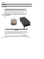
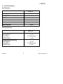
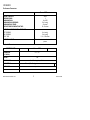
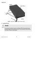
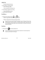
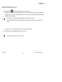
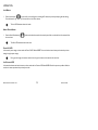
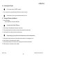
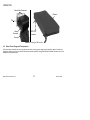
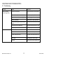
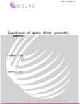
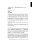
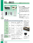
Restore 5000
Alternating Pressure Low Air Loss Mattress System User Manual
This manual MUST be given to the user of the product.
BEFORE using this product, read this manual and save for future reference.
Restorative Innovations. Inc.
2
Restore 5000
CONTENTS
1
GENERAL
4
2
Symbols .................................................................................................................................................................................................................................................... 4
Limited Warranty .................................................................................................................................................................................................................................. 5
OVERVIEW
6
3
Label Location......................................................................................................................................................................................................................................... 6
Typical Product Parameters ................................................................................................................................................................................................................ 7
GENERAL GUIDELINES
9
4
General Guidelines ................................................................................................................................................................................................................................ 9
OPERATION
14
5
Installing the Mattress ......................................................................................................................................................................................................................... 14
Installing the Side Rails ........................................................................................................................................................................................................................ 16
Installing the Power Unit.................................................................................................................................................................................................................... 17
Connecting the Hose .......................................................................................................................................................................................................................... 17
Connecting the Power Cord............................................................................................................................................................................................................. 19
Using the Front Panel.......................................................................................................................................................................................................................... 20
Powering Up the System .................................................................................................................................................................................................................... 25
Placing the Patient on the Mattress ................................................................................................................................................................................................. 25
Transferring Patient From/To a Gurney......................................................................................................................................................................................... 26
Transferring Patient From/To a Wheelchair ................................................................................................................................................................................. 27
Preparing for CPR Procedure ........................................................................................................................................................................................................... 27
About Power Outage and Transportation..................................................................................................................................................................................... 28
MAINTENANCE AND TROUBLESHOOTING
29
Cleaning the System ............................................................................................................................................................................................................................ 29
Troubleshooting ................................................................................................................................................................................................................................... 32
Restore 5000
Restorative Innovations. Inc.
3
1 GENERAL
1 General
1.1
Symbols
Warnings
Signal words are used in this manual and apply to hazards or unsafe practices which could result in personal injury or property damage. See the information below for definitions of the
signal words.
DANGER
Danger indicates an imminently hazardous situation which, if not avoided, will result in death or serious injury.
&
&
!
WARNING
Warning indicates a potentially hazardous situation which, if not avoided, could result in death or serious injury.
CAUTION
Caution indicates a potentially hazardous situation which, if not avoided, may result in property damage or minor injury or both.
IMPORTANT
Indicates a hazardous situation that could result in damage to property if it is not avoided.
Gives useful tips, recommendations and information for efficient, trouble-free use.
Restorative Innovations. Inc.
4
Restore 5000
1 GENERAL
1.2
Limited Warranty
PLEASE NOTE: THE WARRANTY BELOW HAS BEEN DRAFTED TO COMPLY WITH FEDERAL LAW APPLICABLE TO PRODUCTS
MANUFACTURED AFTER JULY 4, 1975.
This warranty is extended only to the original purchaser who purchases this product when new and unused. This warranty is not extended to any other person or entity and is
not transferable or assignable to any subsequent purchaser or owner. Coverage under this warranty will end upon any such subsequent sale or other transfer of title to any other
person. This warranty gives you specific legal rights and you may also have other legal rights which vary from state to state.
Restorative Innovations warrants the mattress and cover when purchased new and unused to be free from defects in materials and workmanship for a period of one year from
the date of purchase, with a copy of the seller’s invoice required for coverage under this warranty.
Restorative Innovations warrants the control unit when purchased new and unused to be free from defects in materials and workmanship for a period of two years from the date
of purchase from Restorative Innovations, with a copy of the seller’s invoice required for coverage under this warranty. If within such warranty period any such product shall be
proven to be defective, such product shall be repaired or replaced. This warranty does not include any labor or shipping charges incurred in replacement part installation or
repair of any such product. Restorative Innovations’ sole obligation and your exclusive remedy under this warranty shall be limited to such repair and/or replacement.
For warranty service, please contact Restorative Innovations. Provide the date of purchase, indicate nature of the defect and, if the product is serialized, indicate the serial number.
The defective unit or parts must be returned for warranty inspection using the serial number, when applicable, as identification within thirty days of return authorization date.
DO NOT return products to our factory without our prior consent.
C.O.D. shipments will be refused; please prepay shipping charges.
LIMITATIONS AND EXCLUSIONS: THE WARRANTY SHALL NOT APPLY TO PROBLEMS ARISING FROM NORMAL WEAR OR FAILURE TO
ADHERE TO THE ENCLOSED INSTRUCTIONS. IN ADDITION, THE FOREGOING WARRANTY SHALL NOT APPLY TO SERIAL NUMBERED
PRODUCTS IF THE SERIAL NUMBER HAS BEEN REMOVED OR DEFACED; PRODUCTS SUBJECTED TO NEGLIGENCE, ACCIDENT,
IMPROPER OPERATION, MAINTENANCE OR STORAGE; OR PRODUCTS MODIFIED WITHOUT RESTORATIVE INNOVATIONS’ EXPRESS WRITTEN
CONSENT INCLUDING, BUT NOT LIMITED TO: MODIFICATION THROUGH THE USE OF UNAUTHORIZED PARTS OR ATTACHMENTS: PRODUCTS
DAMAGED BY REASON OF REPAIRS MADE TO ANY COMPONENT WITHOUT THE SPECIFIC CONSENT OF RESTORATIVE INNOVATIONS;
PRODUCTS DAMAGED BY CIRCUMSTANCES BEYOND RESTORATIVE INNOVATIONS’ CONTROL; PRODUCTS REPAIRED BY ANYONE OTHER THAN
RESTORATIVE INNOVATIONS, SUCH EVALUATION SHALL BE SOLELY DETERMINED BY RESTORATIVE INNOVATIONS. THE FOREGOING EXPRESS
WARRANTY IS EXCLUSIVE AND IN LIEU OF ALL OTHER EXPRESS WARRANTIES WHATSOEVER, WHETHER EXPRESS OR IMPLIED, INCLUDING
THE IMPLIED WARRANTIES OF MERCHANTABILITY AND FITNESS FOR A PARTICULAR PURPOSE AND THE SOLE REMEDY FOR VIOLATIONS OF
ANY WARRANTY WHATSOEVER, SHALL BE LIMITED TO REPAIR OR REPLACEMENT OF THE DEFECTIVE PRODUCT PURSUANT TO THE TERMS
CONTAINED HEREIN. THE APPLICATION OF ANY IMPLIED WARRANTY WHATSOEVER SHALL NOT EXTEND BEYOND THE DURATION OF THE
EXPRESS WARRANTY PROVIDED HEREIN. RESTORATIVE INNOVATIONS SHALL NOT BE LIABLE FOR ANY CONSEQUENTIAL OR INCIDENTAL
DAMAGES WHATSOEVER.
THIS WARRANTY SHALL BE EXTENDED TO COMPLY WITH STATE/PROVINCIAL LAWS AND REQUIREMENTS.
Restore 5000
5
Restorative Innovations. Inc.
2 OVERVIEW
2 Overview
2.1
Label Location
DANGER-EXPLOSION HAZARD: DO NOT use in the presence of flammable anesthetics.
CAUTION: Equipment should be connected to a properly grounded receptacle (3-prong). Risk of
Electrical shock. DO NOT remove back. Disconnect air hose before administering CPR.
This label is on the back of the unit
and also contains the serial
number
WARNING
Patient entrapment with bed side rails may cause injury or death. Mattress MUST fit bed frame and side rails
snugly to prevent patient entrapment. Follow the manufacturer’s instructions. Monitor patient frequently.
Read and understand the Owner’s/Operator’s Manual prior to using this equipment.
p/n1150708 Rev A
Restorative Innovations. Inc.
6
Restore 5000
2 OVERVIEW
2.2
Typical Product Parameters
Electrical Parameters
Restore 5000
INPUT VOLTAGE AC:
90 V
INPUT FREQUENCY:
60 Hz
CURRENT:
1A
MAXIMUM POWER CONSUMPTION:
5±3W
CIRCUIT PROTECTION:
Dual fused, 250 V, 1 A fast blow fuses
MODE OF OPERATION:
Continuous
Environmental Parameters
Restore 5000
OPERATING CONDITIONS
AMBIENT TEMPERATURE:
RELATIVE HUMIDITY:
ATMOSPHERIC PRESSURE:
50° - 104° F
30% - 75% Non-Condensing
70 - 106 kPa
STORAGE AND SHIPPING CONDITIONS
AMBIENT TEMPERATURE:
RELATIVE HUMIDITY:
ATMOSPHERIC PRESSURE:
-40° - 158° F
10% - 100% Non-Condensing
50 - 106 kPa
Restore 5000
7
Restorative Innovations. Inc.
2 OVERVIEW
Performance Parameters
Restore 5000
WEIGHT CAPACITY
PRESSURE ZONE:
MAXIMUM FLOW:
MAXIMUM FLOW PRESSURE:
MAXIMUM FLOW TIMER:
SUPPORT SURFACE INFLATION TIME:
350 lbs
2
8 ± 4 LPM
35 ± 5 mmHg
45 minutes
20 - 45 minutes
PATIENT COMFORT CONTROL PRESSURES
SOFT PRESSURE:
FIRM PRESSURE:
CYCLE TIME:
8 ± 4 mmHg
32 ± 4 mmHg
5, 10, 15, 20 minutes
PATIENT CONTACT:
Control unit and mattress have Latex-Free components
Mechanical Parameters
CONTROL UNIT
Restore 5000
DIMENSIONS
(L X W X H):
9” x 5” x 5”
WEIGHT:
POWER CORD:
CONNECTION:
5 lbs
10 - 14 Feet Long, Hospital Grade
Three ¼” Flow Couplings
PACKAGING:
1 piece/box
AIR FILTER:
Restorative Innovations. Inc.
None
8
Restore 5000
3 GENERAL GUIDELINES
3 General Guidelines
3.1
General Guidelines
WARNING
DO NOT use this product or any available optional equipment without first completely reading and understanding these
instructions and any additional instructional material such as owner’s manuals, service manuals or instruction sheets
supplied with this product or optional equipment. If you are unable to understand the warnings, cautions or instructions,
contact a healthcare professional, dealer or technical personnel before attempting to use this equipment - otherwise, injury
or damage may occur.
!
NOTICE
THE INFORMATION CONTAINED IN THIS DOCUMENT IS SUBJECT TO CHANGE WITHOUT NOTICE.
Check all parts for shipping damage and test before using. In case of damage, DO NOT use.
Contraindications
WARNING
ALWAYS consult the patient’s physician before using the Restore 5000 system.
Restore 5000
9
Restorative Innovations. Inc.
3 GENERAL GUIDELINES
Installation
WARNING
The Restore 5000 is recommended to be installed on medical bed frames with bed side or assist rails. It is preferred that the
rails be in the raised position whenever a patient is on the bed. Health care professionals assigned to each case should
make the final determination whether side or assist rails are warranted after assessing patient risks of entrapment and falls
in accordance with State patient restraint legislation or facility interpretation of such legislation.
Controls on the footboard may be obstructed by the power unit on a few bed frames. It may be necessary to relocate the
power unit. Refer to Installing the Power Unit on page 17.
Check that air hoses and power cord are clear of moving bed components before placing a patient on the bed. Operate all
bed frame motorized functions through their full range of motion to be certain that there is no pulling, interference or
pinching.
Do not strap the mattress to the bed frame at the head and foot ends. Secure ALL mattress straps. Secure the straps to the
bed deck at the head and foot ends and to the frame at the center of the bed. Otherwise damage to the mattress will
occur when the head and foot ends are raised. Refer to Installing the Mattress on page 14.
Restorative Innovations. Inc.
10
Restore 5000
3 GENERAL GUIDELINES
Fire Hazard
DANGER
Smoking
DO NOT SMOKE while using this device. This system uses room air for circulation through the mattress. A cigarette can
burn a hole in the bed surface and cause damage to the mattress. Also, patient clothing, bed sheets, etc. may be
combustible and cause a fire. Failure to observe this warning can result in severe fire, property damage and cause physical
injury or death.
Smoking by visitors in the room will contaminate the system. Therefore, visitor smoking is NOT permitted.
Anesthesia Equipment
There is an explosion risk if used with flammable anesthetics.
Oxygen
There is a possible fire hazard when used with oxygen administering equipment other than nasal mask or half bed tent type.
The oxygen tent should NOT extend below mattress support level.
Restore 5000
11
Restorative Innovations. Inc.
3 GENERAL GUIDELINES
Entrapment May Occur
WARNING
Patient entrapment with bed side rails may cause injury or death. Mattress MUST fit bed frame and side rails snugly to
prevent patient entrapment. Follow the manufacturer’s instructions. Monitor patient frequently. Read and understand the
Owner’s/Operator’s Manual prior to using this equipment.
Proper patient assessment and monitoring, and proper maintenance and use of equipment is required to reduce the risk of
entrapment. Variations in bed rail dimensions, and mattress thickness, size or density could increase the risk of entrapment.
Visit the FDA website at http://www.fda.gov to learn about the risks of entrapment.
Refer to the owner’s manuals for beds and rails for additional product and safety information.
After any adjustments, repair or service and before use, make sure all attaching hardware is tightened securely. Assist rails
with dimensions different from the original equipment supplied or specified by the bed manufacturer may not be
interchangeable and may result in entrapment or other injury.
Restorative Innovations. Inc.
12
Restore 5000
3 GENERAL GUIDELINES
Electrical
DANGER
Electrical shock hazard. DO NOT remove cover. Refer to qualified service personnel.
WARNING
Before performing any maintenance to the power unit, disconnect the power cord from the wall outlet.
DO NOT insert items into any openings of the control unit. Doing so may cause fire or electric shock by shorting the
internal components.
The control unit MUST be kept away from all heat sources and radiators during operation.
Connect the equipment to properly grounded three prong wall outlet using 10-14 ft hospital grade power cord provided
with the product.
Grounding reliability depends upon a properly grounded receptacle (3-prong).
Restore 5000
13
Restorative Innovations. Inc.
4 OPERATION
4 Operation
CAUTION
The control unit and mattress on the Restore 5000 series are designed to be used as a system. DO NOT replace mattresses
or control units with other models or other brands. Otherwise, damage to the system may occur. Contact your supplier to
get the correct replacement if needed.
Restorative Innovations. Inc.
14
Restore 5000
4.1
4 OPERATION
Installing the Mattress
Mattress Replacement System (Restore 5000)
Head End Bed Deck
Center of Bed Frame
CAUTION
DO NOT strap the mattress to the bed frame at
the head and foot ends. Secure ALL mattress
straps. Secure the straps to the bed deck at the
head and foot ends and to the frame at the center
of the bed. Otherwise damage to the mattress will
occur when the head and foot ends are raised.
Foot End Bed Deck
DO NOT Strap Here
The powered mattress comes with ten nylon buckle straps.
1.
Remove the original foam mattress from the bed.
2.
If necessary, lower the side rails to facilitate installation of the mattress.
3.
Unroll the powered mattress and place it on the bed frame.
Ensure that the hose is towards the foot end of the bed.
4.
Use the buckle straps to secure the powered mattress to the bed deck in the following locations:
•
Head End - Head End Bed Deck
•
Foot End - Foot End Bed Deck
•
Center - Center of the Bed Frame
Restore 5000
15
Restorative Innovations. Inc.
4 OPERATION
Head End
Powered Mattress
Buckle
Straps
Hose
Foot End
FIGURE 2 Installing the Mattress - Mattress Replacement System (Restore 5000)
4.2
Installing the Side Rails
WARNING
Patient entrapment with bed side rails may cause injury or death. Mattress MUST fit bed frame and side rails snugly to
prevent patient entrapment. Follow the manufacturer’s instructions. Monitor patient frequently. Read and understand the
Owner’s/Operator’s Manual prior to using this equipment.
Restorative Innovations. Inc.
16
Restore 5000
4 OPERATION
Bed Hooks
Refer to the instructions provided with the side
rails for the installation procedure.
Installing the Power Unit
1.
Swing out the bed hooks on the back of the control unit.
2.
Place the control unit on the footboard.
If the bed does not have a footboard, place the
control unit on a flat surface, leaving room for the
hose to hang down.
FIGURE 3 Installing the Power Unit
4.3
Connecting the Hose
CAUTION
Ensure that the hose connecting the control unit to the mattress is routed such that it cannot be stepped on, kinked,
squeezed or otherwise damaged.
For this procedure, refer to FIGURE 4 on page 18.
1.
Locate the hose at the foot end of the mattress.
2.
Locate the control unit connectors on the right side of the control unit.
3.
Squeeze and hold the tabs on the hose connectors.
4.
Push the hose connectors onto the control connectors until an audible click is heard.
The audible click indicates that the hose connectors are properly engaged with the control connectors.
Restore 5000
17
Restorative Innovations. Inc.
4 OPERATION
Control Unit Connectors
Tab
Hose
Connector
Hose
FIGURE 4 Connecting the Hose
Restorative Innovations. Inc.
18
Restore 5000
4 OPERATION
4.4
Connecting the Power Cord
WARNING
DO NOT alter plug to fit a non-conforming outlet. Instead, have an electrician install a properly grounded 3-prong outlet.
Failure to use the correct plug and outlet can result in a potential safety hazard.
CAUTION
Ensure that the power cord of the control unit is not pinched, or has any objects placed on it, and also ensure it is not
located where it can be stepped on or tripped over.
1.
Examine the hospital grade power cord supplied with the control unit.
2.
Perform one of the following:
3.
•
If the plug is damaged - Call your supplier for a replacement hospital grade cord.
•
If the plug is not damaged - Plug the end of the supplied hospital grade power cord into the power outlet on the side of the control unit.
Plug the other end of the plug into a properly grounded outlet on the wall.
Once the unit is plugged in, an Amber led on the control unit is lit indicating that the system is in stand by mode.
Restore 5000
19
Restorative Innovations. Inc.
4 OPERATION
4.5
Using the Front Panel
DETAIL “B” - MA55
FRONT PANEL
Power Fail LED
Low Pressure
LED
Fowler
Button
Mode Button (Max
Inflate/ Low Air
Loss)
Firm Button
Soft Button
Alarm Silence Button
Static/Alternating Pressure Button
Power Button LCD Display
Lock Button
FIGURE 5 Using the Front Panel
Restorative Innovations. Inc.
20
Restore 5000
4 OPERATION
Power Button
1.
To turn the control unit on or off, press and release the Power button (
).
Once the unit is plugged in, an Amber led on the control unit is lit indicating that the system is in stand by mode. Once the
Power button is pressed and released, a green led illuminates indicating that the control unit is on.
If the power comes on after a power outage, the control unit will go through its system initialization routine for a few
seconds and then resume the desired function.
Static/Alternating Pressure Button
1.
Press the Alternating Pressure button (
) to select between Static Mode and one of four Alternating Pressure Times.
The alternating pressure times indicate the frequency of deflation or inflation of half of the air cushions (even or odd
numbered). For example, 10 minutes is selected. In this example, the even numbered air cushions in the mattress will
deflate, while the odd numbered cushions remain at constant pressure. When 10 minutes has elapsed, the even numbered
air cushions will inflate while the odd numbered cushions remain at constant pressure. When 10 minutes has elapsed again,
the odd numbered air cushions deflate while the even numbered cushions remain at constant pressure. The air cushions
continue to inflate or deflate like this as long as an alternating pressure time has been selected. At all times, half of the air
cushions remain at a constant pressure when an alternating pressure time has been selected.
In Static Mode, all air cushions in the mattress are maintained at constant pressure. The Static LED is illuminated Green.
Adjusting the Minimum Pressure Setting (A/P Low)
The minimum pressure setting during Alternating Pressure is set to 0 (2 mmHg) at the factory. This means that the mattress will deflate as much as
possible during the deflation time when using 10, 15 or 20 minute Alternating Pressure times. The setting can be changed so the mattress will only
deflate to 50% of the selected pressure setting.
1. Ensure the Standby LED is lit.
2.
Perform one of the following:
Restore 5000
21
Restorative Innovations. Inc.
4 OPERATION
•
3.
4.
Read the LCD Display. The LCD Display will flash:
•
0 if the current setting is 0 (2 mmHg).
•
5 if the current setting is 50% of the selected pressure.
Perform the following to toggle between the two settings:
•
5.
Press and hold the Mode and Fowler buttons.
Press the Static/Alternating Pressure button.
Press the Power button to save the setting.
Firm/Soft Buttons
1.
Select comfort pressure settings by pressing Firm (
) or Soft (
) button.
•
Soft Button - Pressing this button reduces the pressure setting in the mattress.
•
Firm Button - Pressing this button increase the pressure setting in the mattress.
The patient comfort pressure ranges from Soft (level 0 = 6±4 mmHg) to Firm (level 9 = 32±6 mmHg). The Comfort Control
LED displays the patient comfort pressure levels from 0 to 9 and provides a guide to the caregiver to set approximate comfort
pressure level depending on the patient weight. If the patient’s weight to height ratio is above average, increase the pressure
setting by approximately 20%.
Fowler Button
1.
Press the Fowler button (
) to activate the patient fowler mode.
The Fowler LED illuminates when in this mode. When this mode is activated, the control unit increases the pressure in
the mattress to prevent the patient from bottoming out.
Restorative Innovations. Inc.
22
Restore 5000
4 OPERATION
Mode Button (Max Inflate/Low Air Loss)
1.
Press the Mode button (
•
) to select the Max Inflate mode or the Low Air Loss mode.
Max Inflate Mode - In this mode, the mattress inflates rapidly to maximum firmness (pressurized to 35 ± 6 mmHg). A series of beeps sound
every three minutes as a reminder that the Max Inflate mode is active. After 45 minutes, the Max Inflate mode deactivates and the control
unit defaults to the previous setting.
It takes 20-45 minutes for the mattress to inflate fully (inflation time depends on size of mattress).
It is recommended that Max Inflate setting be used during patient ingress/egress, patient wound care, patient turning or patient
cleaning.
•
2.
Low Air Loss Mode - In this mode, the mattress goes into on-demand low air loss relief mode.
Press the Mode button to manually disengage Max Inflate or Low Air Loss mode.
This will deactivate the Max Inflate and Low Air Loss LEDs.
Restore 5000
23
Restorative Innovations. Inc.
4 OPERATION
Lock Button
1.
Press the Lock button (
) to lock out all control unit functions, including the On button, to prevent any tampering with the settings.
Press the button for approximately 3-5 seconds for the Lock LED to activate.
The Lock LED illuminates when in this mode.
Alarm Silence Button
1.
Press the Alarm Silence button (
the control unit.
) to silence the alarm that sounds in the event of power failure or when the hose is disconnected from
The Alarm LED illuminates when in this mode.
Power Fail LED
In the event of power outage, an alarm sounds and Power Fail LED flashes AMBER. The control unit has internal memory and retains the previous
settings during the power outage.
During a power outage, the mattress retains the air as long as the mattress is connected to the control unit.
Low Pressure LED
In the event that the mattress hose disconnects, an alarm sounds and Low Pressure LED flashes AMBER. Once the low pressure problem is fixed, the
control unit resumes operation in the previously set mode.
Restorative Innovations. Inc.
24
Restore 5000
4 OPERATION
4.6
Powering Up the System
For this procedure, refer to FIGURE 5 on page 20.
1.
Turn on the power to the system by pressing the Power button on the control unit.
Once the button is released, a green led illuminates when the unit is on.
4.7
1.
Placing the Patient on the Mattress
Perform the following:
Press the Mode button to select Max Inflate Mode.
In this mode, the Max Inflate LED lights up.
2.
After the mattress is fully inflated, place the patient on the mattress.
3.
Ensure that the patient’s feet are towards the foot end of the mattress (the end with the hose).
4.
Center the patient on the bed from side-to-side and head-to-foot.
Special positioning may be required with contracted patients to provide comfortable positions.
5.
After placing the patient, make certain no objects will fall under the patient, such as feeding tubes, IV's etc.
6.
Wait five minutes for the mattress pressure to stabilize.
7.
Once the mattress inflates to its normal size, set the comfort pressure to the desired comfort level.
8.
Wait five minutes for the mattress pressure to stabilize.
Restore 5000
25
Restorative Innovations. Inc.
4 OPERATION
9.
Verify that the patient has not bottomed out by performing the following steps:
A.
Ensure that the patient is lying flat on his/her back in the middle of the mattress.
B.
Place four fingers between the air cushions directly underneath the sacral region of the patient’s body.
C.
Ensure that there is 3 to 4-finger width clearance between the bottom of the patient and the bed frame.
D.
Adjust the comfort setting, if needed.
E.
Wait five minutes for the mattress pressure to stabilize.
F.
Repeat STEPS A-E until patient has not bottomed out and patient comfort is achieved.
10. If the patient feels that the bed is too soft/hard, press the Soft or Firm button to adjust the comfort settings.
11. Use a regular pillow to help support and stabilize the patient's head.
4.8
Transferring Patient From/To a Gurney
WARNING
ALWAYS engage the wheel locks of the bed and the wheel locks of the gurney before transferring the patient between the
bed and the gurney.
1.
Engage the wheel locks of the bed. Refer to the owner’s manual provided with the bed.
2.
Engage the wheel locks of the gurney. Refer to the owner’s manual provided with the gurney.
3.
Press the Max Inflate or Mode button to achieve maximum mattress pressure.
4.
Raise or lower the bed to match the gurney height. Refer to the owner’s manual provided with the bed.
5.
When the mattress has reached maximum firmness, perform one of the following:
•
Bed to Gurney Transfer - Slide the patient onto the gurney.
•
Gurney to Bed Transfer - Slide the patient onto the bed.
Restorative Innovations. Inc.
26
Restore 5000
4 OPERATION
4.9
Transferring Patient From/To a Wheelchair
WARNING
ALWAYS engage the wheel locks of the bed and the wheel locks of the wheelchair before transferring the patient between
the bed and the wheelchair.
1.
Engage the wheel locks of the bed. Refer to the owner’s manual provided with the bed.
2.
Engage the wheel locks of the wheelchair, if applicable. Refer to the owner’s manual provided with the wheelchair.
3.
Press the Max Inflate or Mode button to achieve maximum mattress pressure.
4.
Raise or lower the bed to match the wheelchair height. Refer to the owner’s manual provided with the bed.
5.
When the mattress has reached maximum firmness, perform one of the following:
•
Bed to Wheelchair Transfer - Slide the patient onto the wheelchair.
•
Wheelchair to Bed Transfer - Slide the patient onto the bed.
4.10 Preparing for CPR Procedure
For this procedure, refer to FIGURE 6 on page 28.
1.
Press and hold the tabs on hose connector while pulling the hose from the control unit.
2.
Disconnect the RED CPR connector located on the side of the mattress.
Restore 5000
27
Restorative Innovations. Inc.
4 OPERATION
Control Unit Connectors
Mattress
Tab
Hose
Connector
RED CPR
Connector
Hose
FIGURE 6 Preparing for CPR Procedure
4.11 About Power Outage and Transportation
If the hoses remain connected to the control unit, the mattress retains air during a power outage, during transportation, when the control unit is
unplugged or when the control unit is turned Off. If the hose becomes disconnected or damaged and the mattress deflates, the mattress has a 2-inch
foam pad to provide patient support.
Restorative Innovations. Inc.
28
Restore 5000
5 MAINTENANCE AND TROUBLESHOOTING
5 Maintenance and Troubleshooting
5.1
Cleaning the System
WARNING
Before cleaning or disassembling the Restore 5000, check the underside of the mattress folds for sharp objects such as
scissors, needles, etc. These objects should be removed and discarded before proceeding with further cleaning or
disassembly; otherwise injury or damage to the product may occur.
Because of potential risk of infectious exposure, cleaning with the patient on the bed is not recommended.
All equipment should be inspected. Any item that is visibly soiled with the patient's blood or other body fluids should be
properly cleaned or removed.
Laundry workers should treat all soiled bedding as if it were contaminated with pathogenic microorganisms.
1.
Remove the bedding.
2.
If necessary, inflate the mattress.
3.
Ensure that the control unit is off.
4.
Unplug the power cord from the wall outlet.
5.
Ensure that the underside of the mattress is clear of all sharp objects.
6.
Examine the surface of the control unit and mattress assembly components for visible blood or body fluids.
7.
Perform one of the following:
•
•
If blood is present, decontaminate the product.
i.
Remove all visible soil with disposable paper towels.
ii.
Scrub the area with freshly prepared effective detergent disinfectant solution.
If blood is not present, remove any soil from the cover with paper towels.
Restore 5000
29
Restorative Innovations. Inc.
5 MAINTENANCE AND TROUBLESHOOTING
If soiled, the cover should be removed, cleaned and decontaminated.
8.
Perform the following steps to clean the mattress cover:
A.
Using a clean sponge or paper towel, wipe down the cover surface with a dilute detergent solution of quaternary cleaner disinfectant or
other germicidal detergent solution.
B.
Remove the cover and launder it using the following method:
C AUTION
Laundry workers should always wash their hands before working with clean bedding.
DO NOT overload the machine.
DO NOT use chlorine bleach because it may damage the fabric coating.
High air temperatures will damage the fabrics and void the warranty.
i.
9.
Place the cover in a washing machine.
ii.
Wash with warm water (below 120°F).
iii.
Add detergent and disinfectant according to the manufacturer’s instructions.
iv.
Remove excess water.
v.
Set the dryer to the lowest setting (below 120°F).
vi.
Dry the cover until it is completely dry.
Perform the following steps to clean the control unit and hose fittings:
A. Wipe all controls, chassis and hose fittings with a quaternary disinfectant solution.
B.
Using a nylon brush, gently clean all crevices as they can harbor microorganisms.
C.
Air dry all treated surfaces.
Restorative Innovations. Inc.
30
Restore 5000
5 MAINTENANCE AND TROUBLESHOOTING
10. Perform the following steps to clean the mattress components (air cushions, mattress base, etc.):
A.
B.
Using a clean sponge or paper towel, wipe down the mattress components with a dilute detergent solution of quaternary cleaner disinfectant
or other germicidal detergent solution.
Wipe the mattress components with a clean dry cloth.
Storing the System
1.
Ensure that the control unit is off and disconnect the power cord from the wall outlet.
2.
Clean the system. Refer to Cleaning the System on page 29.
3.
Disconnect the air hose connector(s) from the control unit and allow air to vent from the mattress.
4.
Gently roll up the mattress with minimal handling and agitation.
5.
Ensure the cover surface is inside the roll.
6.
Store the unit, keeping the mattress with the control unit.
Restore 5000
31
Restorative Innovations. Inc.
5 MAINTENANCE AND TROUBLESHOOTING
5.2
Troubleshooting
PROBLEM
CAUSE
SOLUTION
Mattress not inflating
Not alternating properly
Mattress hose disconnected
Connect hose connectors and lock them in
place
Air hose kinked or split
Unkink hose or replace split hose
Major leak in the air cushions or overlay pad
Replace leaking air cushions or overlay pad
Kinked or split manifold
Unkink manifold or replace split manifold
Has power and fuse is good, control unit does not
come on
Send control unit back to factory for repair
Not alternating, solenoid malfunction
Send control unit back to factory for repair
No air, pump malfunction
Send unit for repair
Control unit off
Check power source and turn on unit
Power cord disconnected
Connect power cord to the power source
No power in the power source
Check power source has power and turn it
On
Power outage
Wait till the power source has power
Blown fuse
Replace blown fuse with an equivalent fuse
No power
Restorative Innovations. Inc.
32
Restore 5000
Restorative Innovations, Inc.
54 S. Trooper Rd.
Norristown, PA 19403
610-630-8400
Part No RES5000
Rev CM- 2/13