1
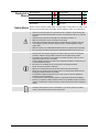
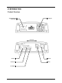
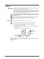
User Manual TABLE OF CONTENTS 1. Before You Begin .............................................................................. 3 What Is Included ............................................................................................... 3 Unpacking Instructions ...................................................................................... 3 Claims ........................................................................................................................ 3 Text Conventions .............................................................................................. 3 Icons .................................................................................................................. 3 Document Information ....................................................................................... 3 Product at a Glance .......................................................................................... 4 Safety Notes ...................................................................................................... 4 2. Introduction ....................................................................................... 5 Product Overview .............................................................................................. 5 Product Dimensions .......................................................................................... 6 3. Setup .................................................................................................. 7 AC Power .......................................................................................................... 7 Fuse Replacement ..................................................................................................... 7 Power Linking............................................................................................................. 8 Mounting ........................................................................................................... 9 Orientation ................................................................................................................. 9 Rigging ....................................................................................................................... 9 4. Operation ..........................................................................................10 Control Panel Operation.................................................................................. 10 Menu Map ....................................................................................................... 10 Configuration (DMX) ....................................................................................... 11 Starting Address....................................................................................................... 11 DMX Personalities.................................................................................................... 11 DMX Channel Assignments and Values ......................................................... 12 13-CH....................................................................................................................... 12 Configuration (Standalone) ............................................................................. 15 Sound Active Mode .................................................................................................. 15 Automatic Mode ....................................................................................................... 15 Manual Pan/Tilt Operation ....................................................................................... 16 Pan/Tilt Angle Restrict.............................................................................................. 16 Display ..................................................................................................................... 16 Master/Slave Mode .................................................................................................. 17 Miscellaneous Operations ............................................................................... 18 Reset Software......................................................................................................... 18 Password Channel ................................................................................................... 18 5. Technical Information ......................................................................19 Product Maintenance ...................................................................................... 19 General Troubleshooting................................................................................. 20 Contact Procedure .......................................................................................... 21 CHAUVET® Contact Information .................................................................... 21 Returning Products to CHAUVET® ................................................................ 21 DMX Primer ..................................................................................................... 22 Introduction .............................................................................................................. 22 DMX Configuration ................................................................................................... 23 DMX Connectivity..................................................................................................... 23 6. Technical Specifications ..................................................................26 Page 2 of 26 Intimidator™ Spot LED 250 User Manual (Rev. 03) 1. BEFORE YOU BEGIN What Is Included Unpacking Instructions Claims Text Conventions Icons 1 x Intimidator™ Spot LED 250 1 x Power Cord 1 x Warranty Card 1 x Quick Reference Guide Immediately upon receipt, carefully unpack the product and check the container to make sure you have received all the parts indicated above in good condition. If the container or the material inside the container (the product and included accessories) appear damaged from shipping, or show signs of mishandling, upon receipt notify the carrier immediately, not CHAUVET®. Failure to do so in a timely manner may invalidate your claim with the carrier. In addition, keep the container and all the packing material for inspection. For other issues such as missing components or parts, damage not related to shipping, or concealed damage, file a claim with CHAUVET® within seven (7) days of receiving the merchandise. Convention 1~512 50/60 Settings Menu > Settings <ENTER> ON Icon Meaning A range of values A set of values of which only one can be chosen A menu option not to be modified A sequence of menu options to be followed A key to be pressed on the product’s control panel A value to be entered or selected Meaning This paragraph contains critical installation, configuration, or operation information. Failure to comply with this information may render the product partially or completely inoperative, cause damage to the product, or cause harm to the user. This paragraph contains important installation or configuration information. Failure to comply with this information may prevent the product from functioning correctly. This paragraph reminds you of useful, although not critical, information. Document Information The information and specifications contained in this document are subject to change without notice. CHAUVET® assumes no responsibility or liability for any errors or omissions that may appear in this manual. CHAUVET® reserves the right to update the existing document or to create a new document to correct any errors or omissions. You can download the latest version of this document from www.chauvetlighting.com. © Copyright 2011 CHAUVET®. All rights reserved Electronically published by CHAUVET® in the United States of America Author Date Editor Date A. Diaz 11/22/11 A. Reiss 11/30/11 Intimidator™ Spot LED 250 User Manual (Rev. 03) Page 3 of 26 Product at a Glance Use on Dimmer Outdoor Use Sound Activated DMX Master/Slave Safety Notes Auto Programs Auto-ranging Power Supply Replaceable Fuse User Serviceable Duty Cycle Please read the following Safety Notes carefully before working with the product. The Notes include important safety information about installation, usage, and maintenance. Page 4 of 26 Always connect the product to a grounded circuit to avoid the risk of electrocution. Always disconnect the product from the power source before cleaning or replacing the fuse. Avoid direct eye exposure to the light source while the product is on. Make sure the power cord is not crimped or damaged. Never disconnect the product from power cord by pulling or tugging on the cord. If mounting the product overhead, always secure to a fastening device using a safety cable. Make sure there are no flammable materials close to the product when operating. Do not touch the product’s housing when operating because it may be very hot. Always make sure that the voltage of the outlet to which you are connecting the product is within the range stated on the decal or rear panel of the product. The product is for indoor use only! (IP20) To prevent risk of fire or shock, do not expose the product to rain or moisture. Always install the product in a location with adequate ventilation, at least 20 in (50 cm) from adjacent surfaces. Be sure that no ventilation slots on the product’s housing are blocked. Never connect the product to a dimmer. Make sure to replace the fuse with another of the same type and rating. Never carry the product from the power cord or any moving part. Always use the hanging/mounting bracket or the handles. The maximum ambient temperature (Ta) is 104° F (40° C). Do not operate the product at higher temperatures. In the event of a serious operating problem, stop using the product immediately. Never try to repair the product. Repairs carried out by unskilled people can lead to damage or malfunction. Please contact the nearest authorized technical assistance center. Keep this User Manual for future consultation. If you sell the product to another user, be sure that they also receive this document. Intimidator™ Spot LED 250 User Manual (Rev. 03) 2. INTRODUCTION Product Overview Control Panel and Button Menu Power In Power Out Cooling Fan DMX Out DMX In Fuse Holder Intimidator™ Spot LED 250 User Manual (Rev. 03) Page 5 of 26 Product Dimensions Page 6 of 26 Intimidator™ Spot LED 250 User Manual (Rev. 03) 3. SETUP AC Power The Intimidator™ Spot LED 250 has an auto-ranging power supply and it can work with an input voltage range of 100~240 VAC, 50/60 Hz. To determine the product’s power requirements (circuit breaker, power outlet, and wiring), use the current value listed on the label affixed to the product’s back panel, or refer to the product’s specifications chart. The listed current rating indicates the product’s average current draw under normal conditions. Always connect the product to a protected circuit (circuit breaker or fuse). Make sure the product has an appropriate electrical ground to avoid the risk of electrocution or fire. Never connect the product to a rheostat (variable resistor) or dimmer circuit, even if the rheostat or dimmer channel serves only as a 0 to 100% switch. Fuse Replacement Follow the instructions below to change the fuse, if necessary. Disconnect the product from the power outlet before replacing the fuse. 1. 2. 3. 4. Wedge the tip of a flat head screwdriver into the slot of the fuse holder. Pry the fuse holder out of the housing. Remove the blown fuse from the holder and replace with a fuse of the exact same type and rating. Insert the fuse holder back in place and reconnect power. Installed fuse (held by plastic clip) Safety cap Spare fuse holder (inside safety cap) The product does not ship with a spare fuse; however, the safety cap has room for a spare. Intimidator™ Spot LED 250 User Manual (Rev. 03) Page 7 of 26 Power Linking The product provides power linking via the IEC outlet located in the back of the unit. Please see the diagram below for further explanation. st 1 Product Power Linking Diagram nd 2 Product rd 3 Product Other products You can power link up to 6 Intimidator™ Spot LED 250 units on 120 VAC or up to 11 Intimidator™ Spot LED 250 units on 230 VAC. The power linking diagram shown above corresponds to the North American version of the product ONLY! If using the product in other markets, you must consult with the local CHAUVET® distributor as power linking connectors and requirements may differ in your country or region. Page 8 of 26 Intimidator™ Spot LED 250 User Manual (Rev. 03) Mounting Before mounting the product, read and follow the safety recommendations indicated in the Safety Notes section (page 2 of this manual). Orientation The Intimidator™ Spot LED 250 may be mounted in any position; however, make sure adequate ventilation is provided around the product. Rigging Mounting Diagram Before deciding on a location for the product, always make sure there is easy access to the product for maintenance and programming purposes. Make sure that the structure or surface onto which you are mounting the product can support the product’s weight. Please see the Technical Specifications section of this manual for weight information. When mounting the product overhead, always use a safety cable. Mount the product securely to a rigging point, whether an elevated platform or a truss. When rigging the product onto a truss, you should use a mounting clamp of appropriate weight capacity. The bracket has a 13 mm hole, which is appropriate for this purpose. When power linking multiple products, you must always consider the length of the power linking cable and mount the products close enough for the cable to reach. The rubber feet also serve as floor supports. When mounting the product on the floor, make sure that the product and cables are away from people and vehicles. Bracket Attachment (x2) Rubber Feet (x4) Safety Loop Attachment Point Intimidator™ Spot LED 250 User Manual (Rev. 03) Page 9 of 26 4. OPERATION Control Panel Operation To access the control panel functions, use the four buttons located underneath the display. Please refer to the Product Overview to see the button locations on the control panel. Button <MODE/ESC> <UP> Menu Map Function Press to find an operation mode or to back out of the current menu option Press to scroll up the list of options or to find a higher value <DOWN> Press to scroll down the list of options or to find a lower value <ENTER> Press to activate a menu option or a selected value Mode Programming Steps DMX Mode 001-512 Description Sets the DMX starting address SLAv (Son) Operation Modes Pan Tilt Display Channel Mode Manual Pan Restrict Manual Tilt Restrict Page 10 of 26 Slave operating mode NASL (SLoU) Automatic Mode, Slow Program NAFA (FASt) Automatic Mode, Fast Program NStS (SrUn) Sound Active Mode Normal Pan PAn Normal Pan operation Inverse Pan r PAn Inverse Pan operation Normal Tilt tiL Normal Tilt operation Inverse Tilt r tiL Inverse Tilt operation Normal Display diS Inverse Display r diS 13-Channel Mode 13CH 8-Channel Mode 8CH Pan 540 PA54 Pan 360 PA36 Pan 180 PA18 Tilt 270 Ti27 Tilt 180 Ti18 Tilt 90 Ti 9 Change the LCD display text position Selects the DMX personality Select Pan angle restrictions Select Tilt angle restrictions Reset rESt Resets fixture Load LoAd Load factory defaults Intimidator™ Spot LED 250 User Manual (Rev. 03) Configuration (DMX) Set the product in DMX mode to control with a DMX controller. 1. Connect the product to a suitable power outlet. 2. Turn the product on. 3. Connect a DMX cable from the DMX output of the DMX controller to the DMX input socket on the product. Starting Address When selecting a starting DMX address, always consider the number of DMX channels the selected DMX mode uses. If you choose a starting address that is too high, you could restrict the access to some of the product’s channels. The Intimidator™ Spot LED 250 uses up to 13 DMX channels in its 13-channel DMX mode, which defines the highest configurable address to 500. If you are not familiar with the DMX protocol, you may refer to the DMX Primer section in the Technical Information chapter. To select the starting address, do the following: 1. Press <MODE/ESC> repeatedly until 001 shows on the display. 2. Press <ENTER>. 3. Use <UP> or <DOWN> to select the starting address. 4. Press <ENTER>. DMX Personalities The Intimidator™ Spot LED 250 has two DMX personalities, an 8-channel personality and a 13-channel personality. To choose which DMX personality to use, follow the steps below: 1. Press <MODE/ESC> repeatedly until either 13CH (to choose the 13-channel personality) or 8CH (to choose the 8-channel personality) shows on the display. 2. Press <ENTER>. Intimidator™ Spot LED 250 User Manual (Rev. 03) Page 11 of 26 DMX Channel Assignments and Values 13-CH Channel Function Value Setting 1 Pan 000 255 0-540° 2 Fine Pan 000 255 Fine control of panning 3 4 5 Tilt Fine Tilt Speed 6 Color Wheel 000 255 000 255 000 255 000 006 007 013 014 020 021 027 028 034 035 041 042 048 049 055 056 064 065 071 072 078 079 085 086 092 093 099 100 106 107 113 114 120 121 127 128 191 7 Gobo Wheel 0-270° Fine control of tilting Pan/Tilt speed (fast to slow) White Yellow Pink Green Red Light Blue Kelly Green Orange Dark Blue White + Yellow Yellow + Pink Pink + Green Green + Red Red + Light Blue Light Blue + Kelly Green Kelly Green + Orange Orange + Dark Blue Dark Blue + White Color cycling rainbow with increasing speed Reverse color cycling rainbow with increasing 192 255 speed 064 071 072 079 080 087 088 095 096 103 104 111 112 119 120 127 128 191 192 255 Gobo 7 shake, from slow to fast Gobo 6 shake, from slow to fast Gobo 5 shake, from slow to fast Gobo 4 shake, from slow to fast Gobo 3 shake, from slow to fast Gobo 2 shake, from slow to fast Gobo 1 shake, from slow to fast Open Cycle effect with increasing speed Reverse cycle effect with increasing speed Continues on the next page Page 12 of 26 Intimidator™ Spot LED 250 User Manual (Rev. 03) Continued from previous page 8 Gobo Rotation 9 Prism 10 Dimmer 11 Shutter 12 Control Functions 13 Auto Programs Intimidator™ Spot LED 250 User Manual (Rev. 03) 000 063 064 147 148 231 232 255 000 015 016 255 000 255 000 003 004 007 008 215 216 255 000 007 008 015 016 023 024 031 032 039 040 047 048 055 056 095 096 103 104 111 112 119 120 127 128 135 136 143 144 151 000 007 008 023 024 039 040 055 056 071 072 087 088 103 104 119 120 135 136 151 152 167 168 183 184 199 200 215 216 231 232 247 248 255 Indexing Rotation effect with increasing speed Reverse rotation effect with increasing speed Gobo bounce Open Prism on 0-100% Closed Open Strobe effect with increasing speed Open No function Blackout while pan/tilt moving Blackout while moving color wheel Blackout while moving gobo wheel Disable blackout while pan/tilt/moving color wheel Disable blackout while pan/tilt/moving gobo wheel Disable blackout while moving all options No function Reset pan Reset tilt Reset color wheel Reset gobo wheel Reset gobo rotation Reset prism Reset focus No function Auto program 1 Auto program 2 Auto program 3 Auto program 4 Auto program 5 Auto program 6 Auto program 7 Auto program 8 Sound controlled program 1 Sound controlled program 2 Sound controlled program 3 Sound controlled program 4 Sound controlled program 5 Sound controlled program 6 Sound controlled program 7 Sound controlled program 8 Page 13 of 26 8-CH Page 14 of 26 Channel 1 2 Function Pan Tilt 3 Color Wheel 4 Gobo Wheel 5 Gobo Rotation 6 Prism 7 Dimmer 8 Shutter Value Setting 000 255 0-540° 000 255 0-270° 000 006 007 013 014 020 021 027 028 034 035 041 042 048 049 055 056 064 065 071 072 078 079 085 086 092 093 099 100 106 107 113 114 120 121 127 128 191 White Yellow Pink Green Red Light Blue Kelly Green Orange Dark Blue White + Yellow Yellow + Pink Pink + Green Green + Red Red + Light Blue Light Blue + Kelly Green Kelly Green + Orange Orange + Dark Blue Dark Blue + White Color cycling rainbow with increasing speed Reverse color cycling rainbow with increasing 192 255 speed 064 071 072 079 080 087 088 095 096 103 104 111 112 119 120 127 128 191 192 255 000 063 064 147 148 231 232 255 000 015 016 255 000 255 000 003 004 007 008 215 216 255 Gobo 7 shake, from slow to fast Gobo 6 shake, from slow to fast Gobo 5 shake, from slow to fast Gobo 4 shake, from slow to fast Gobo 3 shake, from slow to fast Gobo 2 shake, from slow to fast Gobo 1 shake, from slow to fast Open Cycle effect with increasing speed Reverse cycle effect with increasing speed Indexing Rotation effect with increasing speed Reverse rotation effect with increasing speed Gobo bounce Open Prism on 0-100% Closed Open Strobe effect with increasing speed Open Intimidator™ Spot LED 250 User Manual (Rev. 03) Configuration (Standalone) Set the product in one of the standalone modes to control without a DMX controller. 1. Connect the product to a suitable power outlet. 2. Turn the product on. Never connect a product that is operating in any standalone mode (either Static, Automatic, or Sound) to a DMX string connected to a DMX controller. Products in standalone mode may transmit DMX signals that could interfere with the DMX signals from the controller. Sound Active Mode To enable the Sound Active mode, do the following: 1. Press <MODE/ESC> repeatedly until one of the following shows on the display: NASl, NAFA, NStS, SLAv 2. Press <UP> or <DOWN> to select NStS. 3. Press <ENTER>. 4. Turn the music on and adjust the microphone sensitivity knob until the product starts responding to the beat of the music. The product will only respond to low frequencies of music (bass and drums). Automatic Mode To enable the Automatic Mode, follow the instructions below: 1. Press <MODE/ESC> repeatedly until one of the following shows on the display: NASl, NAFA, NStS, SLAv 2. Press <UP> or <DOWN> to select NASl (for a slow light show) or NAFA (for a fast light show). 3. Press <ENTER>. Intimidator™ Spot LED 250 User Manual (Rev. 03) Page 15 of 26 Manual Pan/Tilt Operation To select whether you want the Intimidator™ Spot LED 250 to operate with normal panning or inverted panning, do the following: 1. Press <MODE/ESC> repeatedly until PAn shows on the display. 2. Press <UP> or <DOWN> to select normal pan operation (PAn) or inverse pan operation (r PAn). 3. Press <ENTER>. To select whether you want the Intimidator™ Spot LED 250 to operate with normal tilting or inverted tilting, do the following: 1. Press <MODE/ESC> repeatedly until tiL shows on the display. 2. Press <UP> or <DOWN> to select normal pan operation (tiL) or inverse pan operation (r tiL). 3. Press <ENTER>. Pan/Tilt Angle Restrict You are able to restrict the pan and tilt angles on the Intimidator™ Spot LED 250 to achieve the effect you like. To select which pan angle to use, do the following: 1. Press <MODE/ESC> repeatedly until PA54 shows on the display. 2. Press <UP> or <DOWN> to select either 540° (PA54), 360° (PA36) or 180° (PA18). 3. Press <ENTER>. To select which tilt angle to use, do the following: 1. Press <MODE/ESC> repeatedly until Ti27 shows on the display. 2. Press <UP> or <DOWN> to select either 270° (Ti27), 180° (Ti18) or 90° (Ti 9). 3. Press <ENTER>. Display Page 16 of 26 You are able to flip the LED display for easy readability in any mounting situation. To select your display angle: 1. Press <MODE/ESC> repeatedly until diS shows on the display. 2. Press <UP> or <DOWN> to select normal display mode (diS) or inverse display mode (r diS). 3. Press <ENTER>. Intimidator™ Spot LED 250 User Manual (Rev. 03) Master/Slave Mode The Master/Slave mode allows a single Intimidator™ Spot LED 250 unit (the “master”) to control the actions of one or more Intimidator™ Spot LED 250 units (the “slaves”) without the need of a DMX controller. The master unit will be set to operate in either Automatic or Sound Active mode, while the slave units will be set to operate in Slave Mode. Once set and connected, the slave units will operate in unison with the master unit. Configure the units as indicated below. Slave units: 1. Press <MODE/ESC> repeatedly until SLAv shows on the display. 2. Press <ENTER> to accept. 3. Set the DMX address to 001. 4. 5. Connect the DMX input of the first slave unit to the DMX output of the master unit. Connect the DMX input of the subsequent slave units to the DMX output of the previous slave unit. 6. Finish setting and connecting all the slave units. Master unit: 1. 2. Set the master unit to operate in either Automatic or Sound mode. Make the master unit the first unit in the DMX daisy chain. Configure all the slave units before connecting the master unit to the DMX daisy chain. Never connect a DMX controller to a DMX string configured for Master/Slave operation because the controller may interfere with the signals from the master unit. Do not connect more than 31 slave units to the master unit. Intimidator™ Spot LED 250 User Manual (Rev. 03) Page 17 of 26 Miscellaneous Operations Reset Software To reset the software on the Intimidator™ Spot LED 250, do the following: 1. Press <MODE/ESC> repeatedly until rESt shows on the display. 2. Press <ENTER>. The product will reset all settings in the software to the default factory settings. Password Channel The Intimidator™ Spot LED 250 contains a password-protected mode which allows you to calibrate and troubleshoot any small issues you may have during normal operation. In order to access this mode, do the following: 1. Press and hold <MODE/ESC> for at least 10 seconds. 2. Use the <UP> and <DOWN> buttons to enter the password: 2323. 3. Press <ENTER>. In this mode you have several options for adjustment. Parameter Page 18 of 26 Programming Steps Description Pan Adjust P128 Manually adjust the pan angle Tilt Adjust t128 Manually adjust the tilt angle Gobo Wheel Adjust G128 Manually adjust the gobo wheel Color Wheel Adjust C128 Manually adjust the color wheel Prism Adjust L128 Manually adjust the prism Lamp Brightness Adjust d000 Manually adjust the brightness of the lamp Pan Switch Strength P--0 Adjust the strength of pan switch Tilt Switch Strength t--0 Adjust the strength of tilt switch starting Intimidator™ Spot LED 250 User Manual (Rev. 03) 5. TECHNICAL INFORMATION Product Maintenance Dust build up reduces light output performance and can cause overheating. This can lead to reduction of the light source’s life. To maintain optimum performance and minimize wear, you should clean your lighting products at least twice a month. However, be aware that usage and environmental conditions could be contributing factors to increase the cleaning frequency. To clean the product, follow the instructions below: Unplug the product from power. Wait until the product is cold. Use a vacuum (or dry compressed air) and a soft brush to remove dust collected on the external surface/vents. Clean all glass/transparent surfaces with a mild soap solution, ammonia-free glass cleaner, or isopropyl alcohol. Apply the solution directly to a soft, lint free cotton cloth or a lens cleaning tissue. Softly drag any dirt or grime to the outside of the glass/transparent surface. Gently polish the glass/transparent surfaces until they are free of haze and lint. Always dry the glass/transparent surfaces carefully after cleaning them. Intimidator™ Spot LED 250 User Manual (Rev. 03) Page 19 of 26 General Troubleshooting Symptom Possible Cause Possible Action Excessive load on the circuit Make sure that the total load does not exceed 80% of the breaker or fuse nominal current Short circuit along the power lines Check the power lines and power cords No energy on power outlet Check power outlet Change to another outlet Loose or damaged power cord Check the power cord Blown fuse Replace blown fuse with a good one of the same type and rating Internal problem Send product for repair Wrong starting address on the product Set the correct starting address on the product Use the right fader(s) on the controller Circuit breaker or fuse keeps blowing Product does not power up Product does not respond to DMX Intermittent DMX Problems Wrong DMX personality on the product Set the correct DMX product’s personality Assign the faders accordingly Wrong polarity setting on the DMX controller Change the signal polarity on the controller Loose or damaged DMX cable Check the DMX cable before the faulty unit Internal problem Send product for repair Signal cables are not DMX compatible Replace non DMX cables with true DMX cables Interference with AC or radio signals Keep DMX cables away from AC wires or radio equipment DMX cable too long Install an optically coupled DMX amplifier right before the product with intermittent problems Too many products connected Install an optically coupled DMX amplifier after unit #32 Terminator not connected Install a terminator, as indicated in the DMX Primer section. If you still experience problems after trying the above solutions, contact CHAUVET® Technical Support. Page 20 of 26 Intimidator™ Spot LED 250 User Manual (Rev. 03) Contact Procedure CHAUVET® Contact Information In case you need to return a product or request support, follow the procedure below: If you live in the US, contact CHAUVET® World Headquarters (see below). If you live in the UK or Ireland, contact CHAUVET® Europe Ltd.(see below). If you live in any other country, DO NOT contact CHAUVET®. Instead, contact your distributor of record. Refer to our Web site for contact details of distributors outside the US, United Kingdom, or Ireland. World Headquarters CHAUVET® General Information Address: 5200 NW 108th Avenue Sunrise, FL 33351 Voice: (954) 929-1115 Fax: (954) 929-5560 Toll free: (800) 762-1084 Technical Support Voice: (954) 929-1115 (Press 4) Fax: (954) 756-8015 Email: [email protected] World Wide Web www.chauvetlighting.com United Kingdom & Ireland CHAUVET® Europe Ltd. General Information Address: Unit 1C Brookhill Road Industrial Estate Pinxton, Nottingham, UK NG16 6NT Voice: +44 (0)1773 511115 Fax: +44 (0)1773 511110 Technical Support Email: [email protected] World Wide Web www.chauvetlighting.co.uk If you live outside the US, United Kingdom, or Ireland, contact your distributor of record and follow their instructions on how to return CHAUVET® products to them. Visit our Web site for contact details. Returning Products to CHAUVET® Call the corresponding CHAUVET® Tech Support office and request a Return Merchandise Authorization (RMA) number before shipping the product. Be prepared to provide the model number, serial number, and a brief description of the cause for the return. You must send the merchandise prepaid, in its original box, and with its original packing and accessories. CHAUVET® will not issue call tags. Clearly label the package with the RMA number. CHAUVET® will refuse any product returned without an RMA number. Write the RMA number on a properly affixed label. DO NOT write the RMA number directly on the box. Before sending the product, clearly write the following information on a piece of paper and place it inside the box: Your name Your address Your phone number The RMA number A brief description of the problem Be sure to pack the product properly. Any shipping damage resulting from inadequate packaging will be your responsibility. As a suggestion, proper UPS packing or doubleboxing is always a safe method to use. CHAUVET® reserves the right to use its own discretion to repair or replace returned product(s). Intimidator™ Spot LED 250 User Manual (Rev. 03) Page 21 of 26 DMX Primer Introduction The DMX protocol (USITT DMX512-A) is a networking protocol that enables a universal DMX controller device to control the features of multiple DMX compatible fixtures, whether PAR cans, wash lights, moving heads, followspots, foggers, or proprietary fixture controllers, etc. As any other networking protocol, the USITT DMX512-A describes the physical medium, the signals, and the functions they control. The Physical Medium DMX compatible fixtures are connected to the DMX controller using a DMX connection. This connection consists of a series of wired connections between the DMX controller and the various DMX compatible fixtures, also known as a daisy chain connection. In this type of connection, the DATA OUT of one fixture or the DMX controller connects to the DATA IN of the next fixture, and so on. Each DMX fixture links to the previous and next DMX fixture or controller using a DMX cable. This type of cable consists of a section of shielded, twoconductor twisted pair cable with one 3-pin or 5-pin XLR male connector on one end, and a 3-pin or 5-pin XLR female connector on the other end. The XLR connectors pin-out is as follows: pin 1 is the Common (shield), pin 2 is Signal Negative (S-), and pin 3 is Signal Positive (S+). Note: For DMX, pins 4 and 5 are not used. Page 22 of 26 The Signals The DMX signal stream is unidirectional from the DMX controller to the DMX compatible fixtures. These signals conform to the EIA-485 standard. The stream of DMX signals consists of 512 individual, sequential channels that form a frame. The DMX controller constantly sends frames of DMX signals to the DMX connection, even if not all of the 512 channels are in use. Because of this constant transmission method, there can be only one DMX controller in a DMX connection. If not, the DMX signals sent by one controller would interfere with the signals sent by the other controller(s). DMX Universes A DMX universe is the set of DMX compatible fixtures connected to the same DMX daisy chain using the same set of 512 DMX channels. Each set of 512 channels is referred to as a DMX Universe. In most cases, an installation will consist of only one DMX universe. However, you might find it necessary to define two or more universes because of constrains imposed by distance or the number of features. Most DMX controllers support only one universe, although some DMX controllers may support two or more universes. Each universe will have its own separated DMX daisy chain. A DMX compatible fixture can only be part of a single DMX universe. The Functions Each DMX channel can have any unitary value in the 000~255 range. Each DMX compatible fixture uses as many consecutive DMX channels as features the user can control. The sequential numbers assigned to each DMX channel (1~512) are also known as DMX addresses. The function each DMX channel has, and the results of assigning a value to each depend on the personality (or DMX channel layout) of each controlled fixture. Some fixtures only use a single DMX channel, while others may require 15 or more DMX channels to control all their functions. Personalities are discussed in the next section, DMX Configuration. Intimidator™ Spot LED 250 User Manual (Rev. 03) DMX Configuration The DMX fixture configuration consists in determining how many channels each fixture will need as well as assigning the corresponding DMX channels to each fixture in order to size correctly the DMX controller. Personalities A DMX personality describes what channel or channels control which fixture parameters. A DMX fixture may have many personalities to choose from. Each personality requires a different number of channels, based on the number of features the fixture enables. The number of DMX channels used by a fixture may vary from only one (usually the general dimmer control) to 15 or more. When a job does not require using all the fixture’s capabilities, the user can select a more basic personality (less channels), allowing the DMX controller to accommodate more DMX fixtures. Starting Address For the DMX controller to control each DMX fixture, the user must first configure each fixture’s personality to determine the number of channels required to control the fixture. Each channel will have a DMX address assigned to it. However, since assigning a particular DMX address to each channel is impractical, the user will only need to configure the DMX address on each fixture that corresponds to the fixture’s first channel of control. This is the fixture’s starting address. The fixture will automatically assign the other channels to the subsequent DMX addresses. Once this assignment is complete, and based on the number of channels used, the fixture will respond to the DMX signals sent to the range of DMX channels that begins with the starting address. For example, a fixture that uses six DMX channels with a starting address of 100, will accept DMX data sent by the DMX controller to channels 100, 101, 102, 103, 104, and 105. Assigning Addresses The user must carefully assign the starting addresses for each individual fixture to avoid DMX channel overlapping. If the DMX channels do overlap, the impacted fixtures could operate erratically. However, the user may decide to configure two or more similar fixtures with the same personality and starting address. In this case, all the fixtures with the same starting address will operate in unison. DMX Connectivity Connecting the DMX fixtures to a DMX controller in small to medium installations is usually a rather simple operation that requires a minimum of tools and some planning (not including the actual fixture rigging and configuration). However, in large installations it may be necessary to plan carefully the position and cabling of each fixture to avoid unexpected problems. Fixture Location The order in which the fixtures connect to the DMX controller is not important and has no effect on how a controller communicates to each fixture. However, the user should always define a physical location for the fixtures that provides for the easiest and most direct cabling to the controller and other fixtures. Intimidator™ Spot LED 250 User Manual (Rev. 03) Page 23 of 26 (DMX Connectivity cont.) Number of Fixtures When using a DMX controller, the combined number of channels required by all the fixtures on the DMX daisy chain determines the number of fixtures the DMX controller has to support. Conversely, the number of onboard sliders, page buttons, and fixture buttons limits the number of discrete DMX channels a DMX controller can support. To comply with the EIA-485 standard, which is the base for the USITT DMX512-A protocol, do not connect more than 32 fixtures without using an optically-isolated DMX splitter. Doing otherwise may result in deterioration of the digital DMX signal. DMX Data Cabling You must use DMX compliant data cables to link two or more DMX compatible fixtures. You may purchase CHAUVET® certified DMX cables directly from a dealer/distributor or construct your own cable. USITT recommends limiting the total length of the DMX cable (from the first fixture/controller to the last fixture) to 300~455 m (985~1,500 ft). Making Your Own DMX Cable If you choose to create your own DMX cable, make sure to use data-grade cables that can carry a high frequency signal and are less prone to electromagnetic interference. Use a Belden® 9841 or equivalent cable, which meets the specifications for EIA RS-485 applications. For certain applications, Cat5, Cat5e, or Cat6 may be appropriate. Do not use standard microphone cables for DMX applications because they cannot transmit DMX data reliably over long distances. DMX Cable Characteristics The DMX data cable must have the following characteristics: Type: shielded, 2-conductor twisted pair Maximum capacitance between conductors: 30 pF/ft Maximum capacitance between conductor and shield: 55 pF/ft Maximum resistance: 20 ohms/1000 ft Nominal impedance: 100~140 ohms DMX Cable Connectors Each DMX cable must have a male (3-pin or 5-pin XLR connector) on one end and a female (3-pin or 5-pin XLR connector) on the other end. DMX Connector Configuration To DMX Input (Female) 1 3 2 To DMX Output (Male) Common DMX - To avoid signal transmission problems and interference, connect a DMX signal terminator to the last fixture in the DMX daisy chain, as shown. Page 24 of 26 1 3 2 DMX + 1 3 2 120 ohm, ¼ W resistor between pin 2 (DMX -) and pin 3 (DMX +) on the output of the last fixture. Intimidator™ Spot LED 250 User Manual (Rev. 03) (DMX Connectivity cont.) Test all DMX cables with an ohmmeter to verify their correct polarity and to make sure that there are no short-circuits between any of the pins, or between any pin and ground. If the common wire (shield) touches the chassis ground, a ground loop could form, which may cause the fixture to perform erratically. 3-Pin to 5-Pin Conversion Chart If you use a DMX controller or fixture with a 5-pin DMX connector, you will need to use a 5-pin to 3-pin adapter. The chart below details a proper cable conversion. 3-Pin to 5-Pin Conversion Chart Conductor Ground/Shield Negative (-) signal Positive (+) signal Not Used Not Used DMX Connection 3-Pin Female (Output) Pin 1 Pin 2 Pin 3 5-Pin Male (Input) Pin 1 Pin 2 Pin 3 Pin 4 Pin 5 Make sure that the fixtures with which you are working can operate in DMX mode, not in a proprietary connection mode. Refer to the fixtures’ manual to learn how to enable their respective DMX modes. The procedure below illustrates a possible DMX connection method. 1. 2. 3. 4. 5. Connect the 3-pin, male connector of the first DMX cable to the DMX Output connector (3-pin, female) of the DMX controller. Connect the 3-pin, female connector of the first DMX cable coming from the controller to the DMX Input connector (3-pin, male) of the first DMX fixture. Connect the 3-pin, male connector of the second DMX cable to the DMX Output connector (3-pin, female) of the first DMX fixture. Connect the 3-pin, female connector of the second DMX cable coming from the first DMX fixture to the DMX Input connector of the second DMX compatible fixture. Continue linking the other DMX fixtures in the same way. Intimidator™ Spot LED 250 User Manual (Rev. 03) Page 25 of 26 6. TECHNICAL SPECIFICATIONS Dimensions and Weight Length Width Height Weight 9.3 in (236 mm) 8.1 in (205 mm) 11.3 in (287 mm) 12.6 lbs (5.7 kg) Note: Dimensions in inches rounded to the nearest decimal digit. Power Light Source Photo Optic Thermal DMX Ordering Page 26 of 26 Power Supply Type Range Voltage Selection Switching (internal) 100~240 V, 50/60 Hz Auto-ranging Parameter 120 V, 60 Hz 230 V, 50 Hz Consumption 150 W 157 W Operating 1.3 A 0.7 A Power linking units 6 units 11 units Fuse F 2 A, 250 V F 2 A, 250 V Power I/O US/Worldwide UK/Europe IEC Power input connector IEC Power output connector Edison IEC Power Cord plug Edison (US) Local plug Type Power Lifespan LED 40 W (14.4 A) 50,000 hours Color Quantity Current White 1 350 mA Parameter Illuminance @ 2 m 5970 lx Beam angle 17º Strobe Rate 0-20 Hz Pan & Tilt 540° 270° Pan/Tilt Ranges 540°, 360°, 180° Pan 270°, 180°, 90° Tilt Gobo Size 24 mm outside 20 mm image 1.1 mm thickness Maximum External Temp. Cooling System 104° F (40° C) Convection I/O Connectors Connector Type Channel Range 3-pin XLR Sockets 8, 13 Product Name Item Code Item Number Intimidator™ Spot LED 250 08010462 INTSPOTLED250 Intimidator™ Spot LED 250 User Manual (Rev. 03)