1
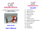
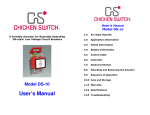
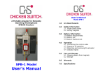
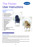
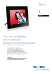
A Portable Actuator for Remotely
Operating the Trip/Close Lever on
Square D BoltLocSwitches
User’s Manual
Model BL-30
For use on Square D
BoltLoc Switch Trip Handles
1.0
Arc-blast Hazards
2.0
Safety Information
2.1 Finger pinch points
2.2 Strong magnets
2.3 Battery precautions
2.4 Charger precautions
3.0
Battery Information
3.0 Battery Requirements
3.1 Battery Life
3.2 Battery Replacement
4.0
Operation
4.1 Connecting the control cable
4.2 Sequence of operation
4.3 Attaching and removing the actuator
4.4 Indicator lights
5.0
Care and Storage
5.1 Cleaning debris from magnets
5.2 Storage
6.0
Warranty
7.0
Specifications
BL-30 Model
User’s Manual
1.0
Arc-blast Hazards
The hazards associated with electrical arc-blasts are
well documented. Studies conducted by numerous
industries and professional organizations have
sought to quantify the intensity of arc-blast, the
risks to personnel, and various methodologies for
mitigating the risks.
Without doubt, increasing the distance between the
arc and a human is the single greatest favorable
factor in reducing injuries.
2.0
Safety Information
ALWAYS connect the control cable to the
actuator BEFORE installing the Chicken
Switch®.
2.1
Finger pinch points
NEVER place your fingers below the red gearbox
enclosure when the control station is connected
to the actuator. The actuator arm/rollers could
pinch your hand/fingers against the frame.
The Chicken Switch® is not a panacea but rather
one more tool available for protecting workers while
they are performing electrical switching.
Using a Chicken Switch® may not negate the need
for additional personal protective measures. The
user is ultimately responsible for evaluating each
situation to determine if additional protective
measures are needed.
WARNING
Electrical switching may present
risk of serious injury or death.
This device should only be used
by qualified persons after
careful analysis of the hazards.
Keep fingers clear of the bottom of the actuator
when the actuator is near a ferrous surface.
2.2
Strong magnets
The holding magnets are very strong. Keep
magnetically-sensitive objects such as watches
or computer disks away from the bottom of the
actuator.
3.0
•
•
3.1
•
3.2
•
Battery Requirements
Sixteen (16) AA alkaline cells are required –
eight cells in each battery holder. Carefully
observe polarity when installing cells.
Rechargeable NiMh or NiCd can be used.
3.3
To connect/disconnect batteries:
Squeeze and
push/pull
Battery Life
A set of fresh alkaline cells should give over
700 operations.
Battery Replacement
ALWAYS disconnect the control cable before
replacing batteries to avoid possible static
damage of the electronics!
3.4
•
CAUTION: Static Discharge Potential
To avoid possible damage to electronic
components disconnect the control cable
before replacing batteries.
WARNING
•
Turn the control station upside down, remove
the endplate retaining knob. Remove the
endplate and slide the cover out as shown
below.
To avoid possible damage
to electronic components
disconnect control cable
before replacing batteries.
4.0
Operation
ALWAYS connect the control cable to the actuator
BEFORE installing the Chicken Switch®.
4.1
Connecting the control cable:
inadvertently trip or close the switch while
installing the actuator.
4. Use the handle on the BoltLoc switch to charge
the trip and close springs.
5. Ensure you are at a safe distance from the circuit
breaker that is to be operated.
6. To trip or close the BoltLoc switch, hold the
ENABLE button while moving the control switch in
the direction of the desired action.
1. Align the arrow on the cable end with the top of
the receptacle.
4.3
2. Push in and engage the threads on the coupling
nut and turn clockwise.
1. Carefully position the BL30 actuator over trip
handle and lock out device
3. After one or two turns of the coupling nut, push
in on the cable end. Repeat this until the
connector is fully seated.
Attaching and Removing the Actuator:
Lockout device
4. Use a similar technique of turn-stop-and-pull to
disengage the cable ends.
4.2
Sequence of Operation:
1. Connect the control cable to the actuator and to
the hand-held controller.
2. Verify that the actuator is in the neutral position.
3. Position the actuator over the Square D BoltLoc
trip handle that is to be operated. The black
rollers on the actuating arm should be on either
side of the trip handle. The rectangular opening
in the actuator should slide over the lock out
device on the BoltLoc switch. (See diagrams in
Section 4.3 for more information.)
CAUTION: Care must be given when installing
the BL30 over the trip handle so as not to
Trip handle is out of
view under the
actuator. Trip
handle is shown on
next page.
2. Once in place, the black rollers on the BL30
should straddle the BoltLoc trip handle and the
magnets should be seated firmly.
4.4
The indicator lights & controls:
NOTE: the indicator lights only work when the
ENABLE button is depressed.
GREEN: indicates the actuator is being
commanded to rotate in the TRIP direction (CCW).
RED: indicates the actuator is being commanded
to rotate in the CLOSE direction (CW).
YELLOW: indicates the actuator is in the neutral
position and the controller and batteries are
healthy.
Trip Handle
Rapidly blinking YELLOW indicates the battery
voltage with zero load has fallen to an
unacceptable level. Operation is inhibited until
batteries with an acceptable voltage level are
installed.
The ENABLE button:
The Enable button must be continuously depressed
in order to command the actuator.
NOTICE:
The Chicken Switch® is designed as a portable
device. It is not designed to remain with the
control unit connected to the actuator for
extended periods of time. To do so will deplete
a fresh set of batteries in approximately four to
five days.
Releasing the enable button has the same affect as
returning the selector switch to neutral – the
actuator moves to neutral.
Note:
If the control switch is held in the trip or close
position for longer than approximately 3 seconds
the drive motor will de-energize and the arm will
remain in driven position. When the control switch
or the enable button is released, the motor will
energize to drive the actuator arm to neutral.
CLOSE
TRIP
R
O
T
A
T
I
O
N
5.0
Care and Storage
5.1
Cleaning the magnets
Over a period of time, the magnets may attract
ferrous debris. Exercise care to avoid setting the
actuator where the magnets might attract
debris. If this does occur, use a paper towel or
nylon bristle brush to clean the face of the
magnets. Keeping the magnet faces clean
ensures that maximum holding power is
maintained.
Min.
5.2
Storage
Max.
Flashing Yellow = Low Voltage Inhibit
ENABLE
Remove all batteries from the control station if
the device will not be used for longer than 6
months.
Never store the batteries where the ambient
temperature might exceed 110º F.
Avoid getting the unit wet or storing it in a high
humidity location.
6.0
Warranty
7.0
MarTek Ltd. guarantees all products manufactured by
MarTek Ltd. only against defects in materials and/or
workmanship for a period of twelve (12) months
commencing on the date the product is received by the
customer. THIS WARRANTY IS IN LIEU OF ALL OTHER
EXPRESS OR IMPLIED WARRANTIES INCLUDING
THOSE OF MERCHANTABILITY AND FITNESS FOR A
PARTICULAR PURPOSE.
MarTek Ltd. will, at its option and its cost (including shipping
expenses for return and re-delivery), repair, replace or
refund the purchase price of any product manufactured by
MarTek Ltd. which has a defect in materials and/or
workmanship. THIS IS CUSTOMER’S EXCLUSIVE
REMEDY FOR BREACH OF WARRANTY. IN NO EVENT
WILL MARTEK LTD’S LIABILITY FOR DAMAGES
(WHETHER ARISING FROM BREACH OF CONTRACT OR
WARRANTY, NEGLIGENCE, STRICT LIABILITY OR
OTHERWISE) EXCEED THE PURCHASE PRICE OF THE
PRODUCT CONCERNED NOR WILL MARTEK LTD. BE
LIABLE FOR PUNITIVE, INCIDENTAL, CONSEQUENTIAL
OR SPECIAL DAMAGES (INCLUDING WITHOUT
LIMITATION LOST PROFITS) EVEN IF ADVISED OF THE
POSSIBILITY OF SUCH DAMAGES.
MarTek Ltd. reserves the right to disallow warranty repairs if
the unit has been disassembled or misused, as determined
by MarTek Ltd. in good faith. Please contact us at (800)248-4958 for a return authorization.
MarTek Ltd.
4806 Chimney Drive
Charleston, WV 25302
1-304-965-9220
1-800-248-4958
Specifications
MECHANICAL
Holding magnets:
Two magnets, each rated @ 36.9 lbs
force, 13.200 Gauss.
Gearmotor:
All metal gears, in a formed metallic
housing. DC brushed, permanent
magnet motor with .375 inch diameter
shaft (9.5 mm).
Projected life:
20,000 operations
ELECTRICAL
Operating voltage:
24 volts DC
Fuse:
5 amp, quick-blow, AGC-5
Power supply:
16 AA alkaline disposable batteries.
When used properly, one set of batteries
should yield over 700 operations.
Control Cable:
30 feet in length (9.1 meters), 5-conductor,
extra-flexible, PUR insulation
Controller:
Requires two-hand operation. The
‘enable’ button must be depressed while
rotating the controller selector switch.
A separate toggle switch allows the user to
select between two levels of rotation (of
the actuator).
A programmable micro-controller manages
control inputs, motor functions, monitors
and limits mechanical travel and performs
timing functions to protect the motor in a
stalled condition.
An intelligent ‘H-bridge’ motor driver
provides start/stop/braking motor
functions. The H-bridge has integral
thermal shutdown protection.
MarTek Ltd.
4806 Chimney Drive
Charleston, WV 25302
1-800-248-4958
www.chickenswitch.com
Chicken Switch is a Registered Trademark of MarTek Ltd.
Copyright 2004-2013, MarTek Ltd. All rights reserved.
User Manual BL-30 Version 3.0