1
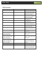
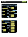
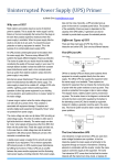
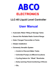
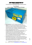
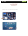
GSM - Relay
Pictures and description
1. User instructions
2. Software updates / custom software updates and Downloads
1: TOP View of GSM Relay board
1: Bottom View of GSM Relay board with SIM-card holder
USB
GSM - Relay
USB
The GSM Relay is a GSM based controllable module from your cell phone with Two (2) inputs and one (1) Relay
output. The main idea for the unit was to reset Router boards on a wireless network which became inaccessible
through the wireless Network however it can be used for lots of different applications, control any electrical
equipment, monitor the voltage of your battery backups, alarm system etc.
Custom code can be written for customers with different needs over the standard program loaded on date of
purchase of the module , customers can re-program the new code onto the device themselves via the on board USB
connection. The unit feature a “SELF PROGRAMMABLE” micro Processor (Explained later in the manual)
The module reacts on specified command SMS’s received, returns SMS’s to the user and can also alert the user if
anyone of the 2 inputs changes state.
2 : User Instructions
The GSM Relay comes pre-programmed with our standard version of the GSM Relay Software.
Insert a SIM card on the bottom of the board into the SIM card holder and secure the socket, the SIM card pin
request must be disabled. Save the phone number of the SIM card to your phone.
Powering up the board: connect 12 to 28 VDC on the 2 way terminal marked “ POS NEG “ 12-24vdc – usually from
backup batteries or a power supply if there is no battery backup system.
The Status LED on the board will light up to indicate that the GSM engine have booted up.
After about 3 to 5 seconds the network LED on the board will start flashing indicating a successful connection to a
GSM network and after about 5 seconds the network led should blink slowly to indicate that it is in sync with the
network and the GSM Relay is now ready to use.
GSM - Relay
USB
SMS Commands :
SMS command
“Com” or “Commands”
OUTPUT RELAY ACTION
N/A
“Stat” or “ Status"
N/A
“Res” or “Reset”
Relay activates for 5 sec
“On”
Relay turns on permanently
“Off”
Turn Relay off after it was on
“ Save”
N/A
“Clear”
N/A
“add082........”
N/A
“wipe”
N/A
“I1xxxxxxxxxx (x = user name
for input 1-max 10 Characters
If name is less than 10
characters fill with spaces
“I2xxxxxxxxxx (x = user name
for input 2-max 10 Characters
If name is less than 10
characters fill with spaces
“Erase” delete the user names
for Input 1 and Input2 and
default back to “INPUT1” and
INPUT2” in reply SMS
Input Auto Reply Jumper J9
Jumper out
Jumper in
N/A
N/A
N/A
N/A
N/A
REPLY SMS TO SENDER
Sends a SMS to user stating all
commands accepted via SMS
Returns a SMS showing device
Status (Status of both Inputs;
Battery input voltage )
Returns a SMS confirming Reset
completed ; (also includes the
status of both Inputs and
Battery input voltage)
Returns a SMS confirming Relay
is on (Relay on !)
Returns a SMS confirming Relay
is Off (Relay Off !)
Saves the primary cell number
to memory / number will not
be lost after total power failure
Remove the saved primary
number from memory
Add a secondary number for
notifications and control to the
unit
Remove the secondary number
from the unit
Assign a user defined name for
Input 1 - SMS returned “Input
name saved”
Assign a user defined name for
Input 2 - SMS returned “Input
name saved”
Deletes the user assigned
names for both inputs and
returns a sms “ Input names
deleted”
No action
Automatically replies with a
SMS if any one of the 2 Inputs
changes state indicating the
state of the inputs and voltage
GSM - Relay
USB
INPUTS:
The 2 Inputs is potential free inputs, no voltages should be injected here.
The user must ensure potential free contacts on inputs – eg: Relay contact or switch or jumper
The board source a negative supply for the input – board marked (NEG IP1 - NEG IP2)
As soon as the unit is powered up it takes a sample of the input status (contact between NEG and IP1 and NEG and
IP2) and saves this as the normal state. If Auto reply jumper J9 is installed, as soon as the status of any input changes
an SMS will be send to notify the user about the change only if the change in input state persists longer than 10
seconds, an SMS will be send every time the status of any input changes for longer than 10 seconds.
If Auto Reply jumper J9 is not installed no SMS’s will be send on input status change.
____________________________________________________________________________________________
Cell Number
After power up the GSM Relay send a sms with text “save” to the units number. The number will be saved as the
primary number and a sms with text “number saved” will be returned to your phone. The primary number have full
control on the unit to change input names , add and remove numbers etc.
Send sms with text “add082(number)” to add a secondary number to the unit. SMS with text “sec num saved” will
be returned to your phone and to the secondary phone number.
The primary number have full control on the unit and can send commands etc to the unit without the secondary
number being notified. Any status request or commands list request from the secondary number will result in a sms
only to the secondary number , but any operational commands like “reset” or “on” etc will result in a sms to the
Primary and secondary number.
Inputs
Standard the unit will refer to “Input1” and “Input2” in a SMS, the user can change this by sending the following
I1xxxxxxxxxx ( Capital letter i with a 1 +10 user characters) eg : I1eskom_ _ _ _ _( _=5spaces at the end) to fill the
string as eskom is only 5 characters
Or eg: I1generator_ ( _1space at the end)to fill the string – generator is 9 characters
Follow the same sequence for Input 2 renaming
Output Relay
10 Amp contact current rating
Common / Normally Open/ Normally Closed terminals available on board from Relay with 3 way barrier terminal
_______________________________________________________________________________________
GSM - Relay
OPERATIONAL SCREENSHOTS
USB
3: Custom Software uploads:
Please visit our website at www.microinstruments.co.za and locate ”MikroBootloader-USB HID” from the
downloads page , download and install the program on your pc.
Once custom code was received for your unit in e-mail save the XXXX.hex file to your desktop.
The Standard code is also available from this page
Have a USB – B cable ready and connected to your a USB port on your pc
STEP1
Make sure the board is not powered from the power input terminals, It will be powered from USB now
Plug the USB-B cable into the USB port on the GSM Relay – the board will power up , your pc will indicate “
Installing device driver “ wait for the Driver to install successfully. If unsuccessful unplug and re-plug the
USB cable to the board after a while, as soon as the Driver has installed successfully, unplug the USB cable
from the board.
STEP2
Run the MikroBootloader USB HID program on the pc , as soon as the program is open connect the board
with the USB cable , The USB icon on the screen will turn red , you have only 5 seconds to click on connect
otherwise the micro will automatically disconnect the USB connection – the History window will indicate a
connection to the target processor.
STEP3
Click on Browse for HEX file button
Locate the XXX.hex file that was saved to the Desktop.
Click on Begin Uploading - a progress bar will indicate the status of the file loading – when completed
uploading leave the board connected , the processor is now programming itself with the new file that was
loaded , the USB will disconnect, as soon as the processor have completed its self-programming the status
led will light and network led will flash indicating the board is functional again.
Unplug the USB now, the board can now be powered normally again.
Please contact : [email protected] for any enquiries or custom software applications for the GSM Relay
board