1
Mitsubishi Safety Programmable Controller
MELSEC-QS CC-Link IE Field
Network Master/Local Module
User’s Manual
(Hardware)
QS0J71GF11-T2
Thank you for purchasing the Mitsubishi safety programmable
controller, MELSEC-QS series. The MELSEC-QS programmable
controller is suitable for establishing safety functions for general
industrial machinery.
Prior to use, please read both this manual and detailed manual
thoroughly to fully understand the product.
MODEL QS0J71GF11-T2-U-HW
MODEL
13J258
CODE
IB(NA)-0800467-C(1406)MEE
© 2011 MITSUBISHI ELECTRIC CORPORATION
SAFETY PRECAUTIONS
(Read these precautions before using this product.)
Before using this product, please read the Safety Guidelines included with the
base unit.
Also, please read this manual, the relevant manuals, the manuals for standard
programmable controllers, and the relevant safety standards carefully, and pay full
attention to safety to handle the product correctly.
PRÉCAUTIONS DE SÉCURITÉ
(Lire ces précautions avant toute utilisation du produit.)
Avant d'utiliser ce produit, prière de lire les "Safety Guidelines" (directive de
sécurité) dans la documentation fournie avec l'unité de base.
De plus, prière de lire ce manuel et la documentation à laquelle il renvoie, les
manuels des automates programmables standard et les normes de sécurité
pertinentes, de façon à traiter le produit correctement.
A-1
CONDITIONS OF USE FOR THE PRODUCT
(1) Although MELCO has obtained the certification for Product's compliance to
the international safety standards IEC61508, EN954-1/ISO13849-1 from
TUV Rheinland, this fact does not guarantee that Product will be free from
any malfunction or failure. The user of this Product shall comply with any
and all applicable safety standard, regulation or law and take appropriate
safety measures for the system in which the Product is installed or used
and shall take the second or third safety measures other than the Product.
MELCO is not liable for damages that could have been prevented by
compliance with any applicable safety standard, regulation or law.
(2) MELCO prohibits the use of Products with or in any application involving,
and MELCO shall not be liable for a default, a liability for defect warranty, a
quality assurance, negligence or other tort and a product liability in these
applications.
(a) power plants,
(b) trains, railway systems, airplanes, airline operations, other
transportation systems,
(c) hospitals, medical care, dialysis and life support facilities or equipment,
(d) amusement equipments,
(e) incineration and fuel devices,
(f) handling of nuclear or hazardous materials or chemicals,
(g) mining and drilling,
(h) and other applications where the level of risk to human life, health or
property are elevated.
A-2
REVISIONS
*The manual number is given on the bottom right of the cover.
Print date
April 2011
September 2011
June 2014
*Manual number
IB(NA)-0800467-A
IB(NA)-0800467-B
IB(NA)-0800467-C
Revision
First edition
Correction of safety precautions
Addition of descriptions of cUL
This manual confers no industrial property rights or any rights of any other kind, nor does it
confer any patent licenses. Mitsubishi Electric Corporation cannot be held responsible for any
problems involving industrial property rights which may occur as a result of using the contents
noted in this manual.
© 2011 MITSUBISHI ELECTRIC CORPORATION
A-3
CONTENTS
1. OVERVIEW..................................................................................................... 1
1.1 Safety Programmable Controller Product List .......................................... 1
2. SPECIFICATIONS .......................................................................................... 2
2.1 Performance Specifications ...................................................................... 2
2.2 Safety Standards ...................................................................................... 3
2.3 Module Replacement................................................................................ 3
3. MOUNTING AND INSTALLATION ................................................................. 4
3.1 Handling Precautions ............................................................................... 4
3.2 Installation Environment ........................................................................... 4
4. PART NAMES................................................................................................. 5
5. EXTERNAL WIRING....................................................................................... 7
5.1 Ethernet Cable Wiring .............................................................................. 7
6. EXTERNAL DIMENSIONS ........................................................................... 10
7. EC DECLARATION OF CONFORMITY FOR MACHINERY DIRECTIVE .... 11
A-4
MANUAL
The manual related to this product is shown below. Please place an
order as needed.
User's manual
Manual name
MELSEC-QS CC-Link IE Field Network Master/Local Module User's
Manual
Manual number
(model code)
SH-080969ENG
(13JZ53)
COMPLIANCE WITH THE EMC, LOW VOLTAGE, AND MACHINERY
DIRECTIVES
(1) Method of ensuring compliance
To ensure that Mitsubishi programmable controllers maintain EMC,
Low Voltage, and Machinery Directives when incorporated into
other machinery or equipment, certain measures may be
necessary. Please refer to the manual included with the base unit.
The CE mark on the side of the programmable controller indicates
compliance with EMC, Low Voltage, and Machinery Directives.
(2) Additional measures
This product complies with the EMC, Low Voltage, and Machinery
Directives. Before using this product, please read this manual, the
relevant manuals, the manuals for standard programmable
controllers, and the safety standards carefully and pay full attention
to safety to handle the product correctly.
The descriptions are based on the requirements of the Directives
and the harmonized standards. However, they do not guarantee
that the entire machinery constructed according to the descriptions
complies with the EMC, Low Voltage, and Machinery Directives.
The manufacture of the machinery must determine the testing
method for compliance and declare conformity to the EMC, Low
Voltage, and Machinery Directives.
A-5
1. OVERVIEW
This manual describes the specifications, part names, and settings of
the QS0J71GF11-T2 CC-Link IE Field Network master/local module
(hereinafter referred to as the QS0J71GF11-T2), which is used with the
MELSEC-QS series safety CPU module.
After unpacking, confirm that the following items are enclosed.
Part name
QS0J71GF11-T2
Module fixing screw
MELSEC-QS CC-Link IE Field Network Master/Local Module
User's Manual (Hardware)
Quantity
1
1
1
1.1 Safety Programmable Controller Product List
Product name
MELSEC-QS CC-Link
IE Field Network
master/local module
Model
Description
A module which is mounted on a safety main base
QS0J71GF11-T2 unit and establishes connection to CC-Link IE
Field Network
1
2. SPECIFICATIONS
2.1 Performance Specifications
Table 2.1 shows the performance specifications of the QS0J71GF11T2. For the general specifications of the QS0J71GF11-T2, refer to the
user's manual for the safety CPU module used.
Table 2.1 Performance specifications
Item
Master station (safety
Number of
station)
connectable
stations per
Local station (standard
network
station)
Number of connectable safety stations per
network
Maximum number of networks
Maximum
Asynchronous mode
number of safety
connections per Synchronous mode
station
Number of safety
Input
inputs/outputs per safety
Output
connection
Communication speed
Network topology
Connection cable
Ethernet
Maximum station-tostation distance
Overall cable distance
Number of cascade
connections
Number of occupied I/O points
Internal current consumption (5VDC)
External dimensions
Weight
Specifications
1 station (Up to 120 slave stations can be
connected to the master station (safety station).)
120 stations
32 stations
239
31 connections
8 connections
8 words
8 words
1Gbps
Line topology, star topology (Coexistence of line
topology and star topology is possible.), and ring
topology
An Ethernet cable that meets the 1000BASE-T
standard: Category 5e or higher (double
shielded, STP), straight cable
100m max. (Compliant with ANSI/TIA/EIA-568-B
(Category 5e))
• Line topology: 12000m
(when cables are connected to 1 master
station and 120 slave stations)
• Star topology: Depends on the system
configuration.
• Ring topology: 12100m
(when cables are connected to 1 master
station and 120 slave stations)
Up to 20
32 points (I/O assignment: Intelligent 32 points)
0.85A
98(H) × 27.4(W) × 115(D) [mm]
0.18kg
2
For transmission delay time or other specifications, refer to the
following.
MELSEC-QS CC-Link IE Field Network Master/Local Module User's
Manual
2.2 Safety Standards
Normes de sécurité
Use the product according to the following safety standards.
Region
International
Europe
North America
Safety standards
IEC61508 Parts 1-7:1998-2000, ISO13849-1: 2006,
IEC61131-2: 2007, IEC61000-6-2: 2005, IEC61000-6-4: 2006,
IEC61784-3:2010, IEC60204-1:2006
EN954-1: 1996, EN ISO13849-1: 2008, EN61131-2: 2007,
EN61000-6-2: 2005, EN61000-6-4: 2007
UL508, NFPA79-2007
Utiliser le produit dans le respect des normes de sécurité suivantes.
Région
International
Europe
Amérique du
Nord
Normes de sécurité
IEC61508 Parts 1-7:1998-2000, ISO13849-1:2006, IEC611312:2007, IEC61000-6-2:2005, IEC61000-6-4:2006, IEC617843:2010, IEC60204-1:2006
EN954-1:1996, EN ISO13849-1:2008, EN61131-2:2007,
EN61000-6-2:2005, EN61000-6-4:2007
UL508, NFPA79-2007
2.3 Module Replacement
Replace the module according to the following replacement cycle.
Module
MELSEC-QS CC-Link IE Field Network master/local
module
3
Replacement cycle
10 years
3. MOUNTING AND INSTALLATION
3.1 Handling Precautions
The following is a list of precautions for handling the master/local
module:
(1) Do not drop or apply strong shock to the module case since it is
made from resin. Doing so may cause failure.
(2) Do not remove the printed-circuit board of the module from the
case. Doing so may cause failure.
(3) Prevent foreign matter such as dust or wire chips from entering the
module. Such foreign matter can cause a fire, failure, or
malfunction.
(4) A protective film is attached to the top of the module to prevent
foreign matter, such as wire chips, from entering the module during
wiring. Do not remove the film during wiring. Remove it for heat
dissipation before system operation.
(5) Before handling the module, touch a grounded metal object to
discharge the static electricity from the human body. Failure to do
so may cause the module to fail or malfunction.
(6) Tighten the screws such as module fixing screws within the
following range.
Screw
Module fixing screw (M3 × 12)
Tightening torque range
0.36 to 0.48N•m
(7) To mount the module, while pressing the module mounting lever
located in the lower part of the module, fully insert the module fixing
projection(s) into the hole(s) in the base unit and press the module
until it snaps into place. Be sure to tighten the module fixing screw
within the specified tightening torque range.
Incorrect mounting may cause malfunction, failure or drop of the
module.
3.2 Installation Environment
For details on installation environment, refer to the following.
QSCPU User's Manual (Hardware Design, Maintenance and
Inspection)
4
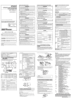
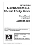
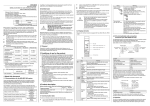
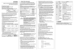
4. PART NAMES
1)
2)
3)
No.
Name
RUN LED
ON
OFF
MST LED
ON
OFF
MODE LED
ON
Flashing
1)
OFF
D LINK LED
ON
Flashing
OFF
SD LED
ON
OFF
RD LED
ON
OFF
Application
Indicates the operating status.
Operates normally.
A hardware failure or a watchdog timer error has occurred.
Indicates the station type.
Operates as a master station (safety station).
Operates as a local station.
Indicates the mode.
In online mode.
In test mode (The module is performing a hardware test, selfloopback test, or loop test.)
In offline mode. (Data link not performed)
Indicates the status of the data link.
Data link in operation (cyclic transmission in progress)
Data link in operation (cyclic transmission stopped)
Data link not performed (disconnected)
Displays the sending status of data.
Sending data.
Data not sent.
Displays the reception status of data.
Receiving data.
Data not received.
5
No.
Name
ERR. LED
ON
Flashing
OFF
L ERR. LED
ON
1)
OFF
ST.NO.
Application
Indicates the error status of the master/local module.
One of the following errors has occurred:
• A stop error occurs in the safety CPU module.
• An error was detected in all stations.
• Modules with same station number exist on the network.
• A network parameter is corrupted.
• The network parameter does not match the installation
status. (Reserved station specification, number of
connected stations, network number etc.)
A data link faulty station was detected.
Working normally.
Indicates the error status of the received data and the circuit.
• The module has received abnormal data.
• The module is performing loopback.
• The module has received normal data.
• The module is not performing loopback.
Displays the station number of the master/local module.
Displays the station number.
(Ex.) Station No. 15
1
ON
1
4
100
1
10
10 + 5 = 15
OFF
P1
L ER
LED
2)
LINK
LED
ON
OFF
ON
OFF
P2
3)
L ER LED
LINK LED
Serial number
display
Operates as a master station (safety station). (station No. 0)
PORT1 connector for CC-Link IE Field Network (RJ45
connector)
Connect an Ethernet cable.
• The module has received abnormal data.
• The module is performing loopback.
• The module has received normal data.
• The module is not performing loopback.
Linkup in progress.
Linkdown in progress.
PORT2 connector for CC-Link IE Field Network (RJ45
connector)
Connect an Ethernet cable.
(Same as the "P1" connector)
Displays the serial number printed on the rating plate.
6
5. EXTERNAL WIRING
5.1 Ethernet Cable Wiring
Câblage pour câble Ethernet
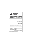
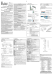
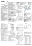
(1) Network topology
Topologie du réseau
This section describes available network topologies.
Cette section présente les topologies réseau disponibles.
Switching hub
Star topology
Line topology
Star and line topologies mixed
Switching hub
Switching hub
Ring topology
French
Concentrateur de commutation
Topologie en étoile
Topologie en ligne
Topologies mixtes en étoile et en
Star and line topologies mixed
ligne
Ring topology
Topologie en anneau
For details on the network topologies, refer to the following.
MELSEC-QS CC-Link IE Field Network Master/Local Module
User's Manual
Pour le détail des topologies réseau, voir ce qui suit.
MELSEC-QS CC-Link IE Field Network Master/Local Module
User's Manual
English
Switching hub
Star topology
Line topology
7
(2) Connecting the cable
Raccordement du câble
PORT1 and PORT2 need not to be distinguished.
Il n'y a pas de distinction particulière à faire entre PORT1 et
PORT2.
(a) When only one connector is used in star topology, either
PORT1 or PORT2 is applicable.
Si on utilise un seul connecteur en topologie étoile, PORT1
ou PORT2 peuvent être utilisés indifféremment.
L ER
P1
LINK
Either one can be used.
L ER
P2
LINK
QS0J71GF11-T2
(b) When using two connectors for line topology and ring
topology, an Ethernet cable can be connected to the
connectors in any combination.
Si on utilise deux connecteurs pour la topologie en ligne et
pour la topologie en anneau, la combinaison de
raccordement des câbles Ethernet aux connecteurs est
indifférente.
Connection between
PORT1s or PORT2s
L ER
L ER
Connection between
PORT1 and PORT2
L ER
L ER
L ER
L ER
P1
P1
P1
P1
P1
P1
LINK
LINK
LINK
LINK
LINK
LINK
L ER
L ER
L ER
L ER
L ER
P2
P2
P2
P2
P2
LINK
LINK
LINK
LINK
LINK
QS0J71GF11-T2
QS0J71GF11-T2
QS0J71GF11-T2
QS0J71GF11-T2
QS0J71GF11-T2
L ER
P2
LINK
QS0J71GF11-T2
French
On peut utiliser l'un comme l'autre.
Raccordement entre PORT1s ou
PORT2s
Connexion entre PORT1 et
PORT2
English
Either one can be used.
Connection between PORT1s or
PORT2s
Connection between PORT1 and
PORT2
8
(3) Precautions
This section describes wiring precautions.
(a) Handling
• Place the Ethernet cable in a duct or clamp them. If not,
dangling cable may swing or inadvertently be pulled, resulting in
damage to the module or cables or malfunction due to poor
contact.
• Do not touch the core of the cable-side or module-side
connector, and protect it from dirt or dust. If oil from your hand,
dirt or dust is attached to the core, it can increase transmission
loss, arising a problem in data link.
• Check the following:
• Is any Ethernet cable disconnected?
• Is any of the Ethernet cables shorted?
• Are the connectors securely connected?
(b) Broken cable latch
Do not use Ethernet cables with broken latches. Doing so may
cause the cable to unplug or malfunction.
(c) Connecting and disconnecting the Ethernet cable
Hold the connector part when connecting and disconnecting
the Ethernet cable. Pulling a cable connected to the module
may damage the module or cable, or result in malfunction due
to poor contact.
(d) Connectors without Ethernet cable
Attached connector cover should be placed to prevent foreign
matter such as dirt or dust.
(e) Maximum station-to-station distance (maximum cable length)
The maximum station-to-station distance is 100m. However,
the distance may be shorter depending on the operating
environment of the cable. For details, contact your cable
manufacturer.
(f)
Bend radius
The bend radius of the Ethernet cable is limited. For details,
see the specifications of the Ethernet cable to be used.
(g) Network configuration
For wiring, check (1), (2), and (3) in this section to prevent
incorrect wiring.
9
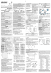
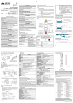
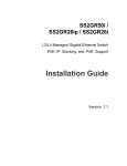
4
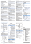
98
6. EXTERNAL DIMENSIONS
23
27.4
115
(Unit: mm)
10
7. EC DECLARATION OF CONFORMITY FOR MACHINERY
DIRECTIVE
11
12
MEMO
13
WARRANTY
Please confirm the following product warranty details before using this product.
1. Limited Warranty and Product Support.
a.Mitsubishi Electric Company ("MELCO") warrants that for a period of eighteen (18)
months after date of delivery from the point of manufacture or one year from date of
Customer's purchase, whichever is less, Mitsubishi MELSEC Safety programmable logic
controllers (the "Products") will be free from defects in material and workmanship.
b.At MELCO's option, for those Products MELCO determines are not as warranted,
MELCO shall either repair or replace them or issue a credit or return the purchase price
paid for them.
c.For this warranty to apply:
(1) Customer shall give MELCO (i) notice of a warranty claim to MELCO and the
authorized dealer or distributor from whom the Products were purchased, (ii) the
notice shall describe in reasonable details the warranty problem, (iii) the notice shall
be provided promptly and in no event later than thirty (30) days after the Customer
knows or has reason to believe that Products are not as warranted, and (iv) in any
event, the notice must given within the warranty period;
(2) Customer shall cooperate with MELCO and MELCO's representatives in MELCO's
investigation of the warranty claim, including preserving evidence of the claim and its
causes, meaningfully responding to MELCO's questions and investigation of the
problem, grant MELCO access to witnesses, personnel, documents, physical
evidence and records concerning the warranty problem, and allow MELCO to
examine and test the Products in question offsite or at the premises where they are
installed or used; and
(3) If MELCO requests, Customer shall remove Products it claims are defective and ship
them to MELCO or MELCO's authorized representative for examination and, if found
defective, for repair or replacement. The costs of removal, shipment to and from
MELCO's designated examination point, and reinstallation of repaired or replaced
Products shall be at Customer's expense.
(4) If Customer requests and MELCO agrees to effect repairs onsite at any domestic or
overseas location, the Customer will pay for the costs of sending repair personnel and
shipping parts. MELCO is not responsible for any re-commissioning, maintenance, or
testing on-site that involves repairs or replacing of the Products.
d.Repairs of Products located outside of Japan are accepted by MELCO's local authorized
service facility centers ("FA Centers"). Terms and conditions on which each FA Center
offers repair services for Products that are out of warranty or not covered by MELCO's
limited warranty may vary.
e.Subject to availability of spare parts, MELCO will offer Product repair services for (7)
years after each Product model or line is discontinued, at MELCO's or its FA Centers'
rates and charges and standard terms in effect at the time of repair. MELCO usually
produces and retains sufficient spare parts for repairs of its Products for a period of seven
(7) years after production is discontinued.
f. MELCO generally announces discontinuation of Products through MELCO's Technical
Bulletins. Products discontinued and repair parts for them may not be available after their
production is discontinued.
2. Limits of Warranties.
a.MELCO does not warrant or guarantee the design, specify, manufacture, construction or
installation of the materials, construction criteria, functionality, use, properties or other
characteristics of the equipment, systems, or production lines into which the Products
may be incorporated, including any safety, fail-safe and shut down systems using the
Products.
b.MELCO is not responsible for determining the suitability of the Products for their intended
purpose and use, including determining if the Products provide appropriate safety
margins and redundancies for the applications, equipment or systems into which they are
incorporated.
c.Customer acknowledges that qualified and experienced personnel are required to
determine the suitability, application, design, construction and proper installation and
integration of the Products. MELCO does not supply such personnel.
d.MELCO is not responsible for designing and conducting tests to determine that the
Product functions appropriately and meets application standards and requirements as
installed or incorporated into the end-user's equipment, production lines or systems.
e.MELCO does not warrant any Product:
(1) repaired or altered by persons other than MELCO or its authorized engineers or FA
Centers;
(2) subjected to negligence, carelessness, accident, misuse, or damage;
(3) improperly stored, handled, installed or maintained;
(4) integrated or used in connection with improperly designed, incompatible or defective
hardware or software;
(5) that fails because consumable parts such as batteries, backlights, or fuses were not
tested, serviced or replaced;
(6) exchange of a consumable part such as batteries, backlights, or fuses;
(7) operated or used with equipment, production lines or systems that do not meet
applicable and commensurate legal, safety and industry-accepted standards;
(8) operated or used in abnormal applications;
(9) installed, operated or used in contravention of instructions, precautions or warnings
contained in MELCO's user, instruction and/or safety manuals, technical bulletins and
guidelines for the Products;
(10)used with obsolete technologies or technologies not fully tested and widely accepted
and in use at the time of the Product's manufacture;
(11)subjected to excessive heat or moisture, abnormal voltages, shock, excessive
vibration, physical damage or other improper environment; or
(12)damaged or malfunctioning due to Acts of God, fires, acts of vandals, criminals or
terrorists, communication or power failures, or any other cause or failure that results
from circumstances beyond MELCO's control.
f. All Product information and specifications contained on MELCO's website and in
catalogs, manuals, or technical information materials provided by MELCO are subject to
change without prior notice.
g.The Product information and statements contained on MELCO's website and in catalogs,
manuals, technical bulletins or other materials provided by MELCO are provided as a
guide for Customer's use. They do not constitute warranties and are not incorporated in
the contract of sale for the Products.
h.These terms and conditions constitute the entire agreement between Customer and
MELCO with respect to warranties, remedies and damages and supersede any other
understandings, whether written or oral, between the parties. Customer expressly
acknowledges that any representations or statements made by MELCO or others
concerning the Products outside these terms are not part of the basis of the bargain
between the parties and are not factored into the pricing of the Products.
i. THE WARRANTIES AND REMEDIES SET FORTH IN THESE TERMS ARE THE
EXCLUSIVE AND ONLY WARRANTIES AND REMEDIES THAT APPLY TO THE
PRODUCTS.
j. MELCO DISCLAIMS THE IMPLIED WARRANTIES OF MERCHANTABILITY AND
FITNESS FOR A PARTICULAR PURPOSE.
3. Limits on Damages.
a.MELCO'S MAXIMUM CUMULATIVE LIABILITY BASED ON ANY CLAIMS FOR BREACH
OF WARRANTY OR CONTRACT, NEGLIGENCE, STRICT TORT LIABILITY OR OTHER
THEORIES OF RECOVERY REGARDING THE SALE, REPAIR, REPLACEMENT,
DELIVERY, PERFORMANCE, CONDITION, SUITABILITY, COMPLIANCE, OR OTHER
ASPECTS OF THE PRODUCTS OR THEIR SALE, INSTALLATION OR USE SHALL BE
LIMITED TO THE PRICE PAID FOR PRODUCTS NOT AS WARRANTED.
b.Although MELCO has obtained the certification for Product's compliance to the
international safety standards IEC61508 and EN954-1/ISO13849-1 from TUV Rheinland,
this fact does not guarantee that Product will be free from any malfunction or failure. The
user of this Product shall comply with any and all applicable safety standard, regulation or
law and take appropriate safety measures for the system in which the Product is installed
or used and shall take the second or third safety measures other than the Product.
MELCO is not liable for damages that could have been prevented by compliance with any
applicable safety standard, regulation or law.
c.MELCO prohibits the use of Products with or in any application involving power plants,
trains, railway systems, airplanes, airline operations, other transportation systems,
amusement equipments, hospitals, medical care, dialysis and life support facilities or
equipment, incineration and fuel devices, handling of nuclear or hazardous materials or
chemicals, mining and drilling, and other applications where the level of risk to human life,
health or property are elevated.
d.MELCO SHALL NOT BE LIABLE FOR SPECIAL, INCIDENTAL, CONSEQUENTIAL,
INDIRECT OR PUNITIVE DAMAGES, FOR LOSS OF PROFITS, SALES, OR
REVENUE, FOR INCREASED LABOR OR OVERHEAD COSTS, FOR DOWNTIME OR
LOSS OF PRODUCTION, FOR COST OVERRUNS, OR FOR ENVIRONMENTAL OR
POLLUTION DAMAGES OR CLEAN-UP COSTS, WHETHER THE LOSS IS BASED ON
CLAIMS FOR BREACH OF CONTRACT OR WARRANTY, VIOLATION OF STATUTE,
NEGLIGENCE OR OTHER TORT, STRICT LIABILITY OR OTHERWISE.
e.In the event that any damages which are asserted against MELCO arising out of or
relating to the Products or defects in them, consist of personal injury, wrongful death and/
or physical property damages as well as damages of a pecuniary nature, the disclaimers
and limitations contained in these terms shall apply to all three types of damages to the
fullest extent permitted by law. If, however, the personal injury, wrongful death and/or
physical property damages cannot be disclaimed or limited by law or public policy to the
extent provided by these terms, then in any such event the disclaimer of and limitations
on pecuniary or economic consequential and incidental damages shall nevertheless be
enforceable to the fullest extent allowed by law.
f. In no event shall any cause of action arising out of breach of warranty or otherwise
concerning the Products be brought by Customer more than one year after the cause of
action accrues.
g.Each of the limitations on remedies and damages set forth in these terms is separate and
independently enforceable, notwithstanding the unenforceability or failure of essential
purpose of any warranty, undertaking, damage limitation, other provision of these terms or
other terms comprising the contract of sale between Customer and MELCO.
4. Delivery/Force Majeure.
a.Any delivery date for the Products acknowledged by MELCO is an estimated and not a
promised date. MELCO will make all reasonable efforts to meet the delivery schedule set
forth in Customer's order or the purchase contract but shall not be liable for failure to do
so.
b.Products stored at the request of Customer or because Customer refuses or delays
shipment shall be at the risk and expense of Customer.
c.MELCO shall not be liable for any damage to or loss of the Products or any delay in or
failure to deliver, service, repair or replace the Products arising from shortage of raw
materials, failure of suppliers to make timely delivery, labor difficulties of any kind,
earthquake, fire, windstorm, flood, theft, criminal or terrorist acts, war, embargoes,
governmental acts or rulings, loss or damage or delays in carriage, acts of God, vandals
or any other circumstances reasonably beyond MELCO's control.
5. Choice of Law/Jurisdiction.
These terms and any agreement or contract between Customer and MELCO shall be
governed by the laws of the State of New York without regard to conflicts of laws. To the
extent any action or dispute is not arbitrated, the parties consent to the exclusive
jurisdiction and venue of the federal and state courts located in the Southern District of the
State of New York. Any judgment there obtained may be enforced in any court of
competent jurisdiction.
6. Arbitration.
Any controversy or claim arising out of, or relating to or in connection with the Products,
their sale or use or these terms, shall be settled by arbitration conducted in accordance
with the Center for Public Resources (CPR) Rules for Non-Administered Arbitration of
International Disputes, by a sole arbitrator chosen from the CPR's panels of distinguished
neutrals. Judgment upon the award rendered by the Arbitrator shall be final and binding
and may be entered by any court having jurisdiction thereof. The place of the arbitration
shall be New York City, New York. The language of the arbitration shall be English. The
neutral organization designated to perform the functions specified in Rule 6 and Rules
7.7(b), 7.8 and 7.9 shall be the CPR.
Country/Region Sales office/Tel
Country/Region Sales office/Tel
USA
Mitsubishi Electric Automation lnc.
500 Corporate Woods Parkway, Vernon
Hills, IL 60061, USA
Tel : +1-847-478-2100
South Africa
CBI-Electric.
Private Bag 2016, ZA-1600 Isando,
South Africa
Tel : +27-11-977-0770
Brazil
MELCO-TEC Representacao Comercial
e Assessoria Tecnica Ltda.
Av. Paulista, 1439, cj74, Bela Vista,
Sao Paulo CEP: 01311-200-SP Brazil
Tel : +55-11-3146-2200
China
Mitsubishi Electric Automation (China) Ltd.
No.1386 Hongqiao Road, Mitsubishi
Electric Automation Center, Changning
District, Shanghai, China
Tel : +86-21-2322-3030
Germany
Mitsubishi Electric Europe B.V. German
Branch
Gothaer Strasse 8, D-40880 Ratingen,
Germany
Tel : +49-2102-486-0
Taiwan
Setsuyo Enterprise Co., Ltd.
6F., No.105, Wugong 3rd Road, Wugu
District, New Taipei City 24889, Taiwan,
R.O.C.
Tel : +886-2-2299-2499
UK
Mitsubishi Electric Europe B.V. UK Branch
Travellers Lane, Hatfield, Hertfordshire,
AL10 8XB, UK.
Tel : +44-1707-27-6100
Korea
Italy
Mitsubishi Electric Europe B.V. Italian
Branch
Viale Colleoni 7-20864 Agrate Brianza
(Milano), Italy
Tel : +39-039-60531
Mitsubishi Electric Automation
Korea Co., Ltd.
3F, 1480-6, Gayang-Dong, Gangseo-Gu,
Seoul, 157-200, Korea
Tel : +82-2-3660-9530
Singapore
Mitsubishi Electric Europe B.V. Spanish
Branch
Carretera de Rubi 76-80.AC.420, E-08190
Sant Cugat del Valles (Barcelona), Spain
Tel : +34-93-565-3131
Mitsubishi Electric Asia Pte, Ltd. Industrial
Division
307, Alexandra Road, Mitsubishi Electric
Building, Singapore, 159943
Tel : +65-6470-2308
Thailand
Mitsubishi Electric Automation (Thailand)
Co., Ltd.
Bang-Chan Industrial Estate No.111
Soi Serithai 54,
T.Kannayao, A.Kannayao, Bangkok
10230 Thailand
Tel : +66-2906-3238
Indonesia
P. T. Autoteknindo Sumber Makmur
Muara Karang Selatan, Block A / Utara
No.1 Kav. No. 11,
Kawasan Industri Pergudangan,
Jakarta-Utara 14440, P.O, Box 5045,
Indonesia
Tel : +62-21-663-0833
India
Mitsubishi Electric India Pvt. Ltd.
2nd Floor, Tower A & B, Cyber Greens,
DLF Cyber City, DLF Phase-III,
Gurgaon-122002 Haryana, India
Tel : +91-124-463-0300
Australia
Mitsubishi Electric Australia Pty. Ltd.
348 Victoria Road PO BOX11,
Rydalmere, N.S.W 2116, Australia
Tel : +61-2-9684-7777
Spain
France
Mitsubishi Electric Europe B.V. French
Branch
25, Boulevard des Bouvets, F-92741
Nanterre Cedex, France
Tel : +33-1-5568-5568
Czech Republic Mitsubishi Electric Europe B.V.-o.s.Czech
office
Avenir Business Park, Radicka 751/113e,
158 00 Praha5, Czech Republic
Tel : +420-251-551-470
Poland
Mitsubishi Electric Europe B.V. Polish
Branch
ul. Krakowska 50, 32-083 Balice, Poland
Tel : +48-12-630-47-00
Russia
Mitsubishi Electric Europe B.V. Russian
Branch St.Petersburg office
Piskarevsky pr. 2, bld 2, lit "Sch", BC
"Benua", office 720; 195027,
St. Petersburg, Russia
Tel : +7-812-633-3497
HEAD OFFICE : TOKYO BUILDING, 2-7-3 MARUNOUCHI, CHIYODA-KU, TOKYO 100-8310, JAPAN
NAGOYA WORKS : 1-14, YADA-MINAMI 5-CHOME, HIGASHI-KU, NAGOYA, JAPAN
When exported from Japan, this manual does not require application to the Ministry
of Economy, Trade and Industry for service transaction permission.
Specifications subject to change without notice.