1
SGA/A & SGA/D
Analogue Strain Gauge Amplifiers
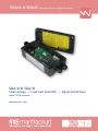
SGA/A & SGA/D
Strain Gauge | Load Cell Amplifier | Signal Conditioner
Issue 7 PCB onwards
mantracourt.com
SGA/A & SGA/D Manual
Contents
Chapter 1 Introduction to SGA/A & SGA/D ......................................................................................... 2
The Strain Gauge Amplifier SGA ....................................................................................................... 2
Figure 1.1 SGA Signal Conditioner ..................................................................................................... 2
Chapter 2 Installing the SGA/A & SGA/D ............................................................................................ 3
Pre Installation ............................................................................................................................ 3
Figure 2.1 Dimensions ................................................................................................................... 3
Cabling ..................................................................................................................................... 4
Power Connection ........................................................................................................................ 4
Figure 2.2 Power Connection ........................................................................................................... 4
Figure 2.3 IS1224 Module Connections ................................................................................................ 4
Figure 2.4 Input (Sensor) Connections ................................................................................................ 5
Table 2.1 ................................................................................................................................... 5
Output Connections ...................................................................................................................... 6
Figure 2.5 Output Connections ......................................................................................................... 6
Chapter 3 Switch Settings ............................................................................................................. 7
Figure 3.1 Output Settings–Switch 4 .................................................................................................. 7
Table 3.1 Output Option ................................................................................................................ 7
Table 3.2 Switch 4........................................................................................................................ 7
Table 3.3 ................................................................................................................................... 8
Output Filter Settings –Switch 3 ....................................................................................................... 8
Table 3.4 Switch 3........................................................................................................................ 8
Table 3.5 ................................................................................................................................... 9
Output Current Mode and Input Filter Settings – Jumpers JP1, JP2 & JP3 ..................................................... 9
Figure 3.2 .................................................................................................................................. 9
Span (Gain) Setting Switch SW1 ....................................................................................................... 10
Table 3.6 – SW1 .......................................................................................................................... 10
Table 3.7 .................................................................................................................................. 11
Shunt Calibration Switch SW1/8 ...................................................................................................... 11
Table 3.8 .................................................................................................................................. 11
Figure 3.3 ................................................................................................................................. 11
Zero (Offset) Setting Switch SW2 ..................................................................................................... 11
Table 3.9 .................................................................................................................................. 12
Table 3.10 ................................................................................................................................ 12
Chapter 4 Calibration .................................................................................................................. 13
Output ..................................................................................................................................... 13
Zero Offset ............................................................................................................................... 13
Sensitivity ................................................................................................................................. 13
Figure 4.1 Calibration Connections Using a Millivolt Source ..................................................................... 15
Chapter 5 The SGABCM Bridge Completion Module ............................................................................. 16
Half Bridge ................................................................................................................................ 16
Quarter Bridge ........................................................................................................................... 16
Shunt Calibration ........................................................................................................................ 17
Remote Shunt Calibration .............................................................................................................. 18
Chapter 6 Troubleshooting ........................................................................................................... 19
Chapter 7 Product Care ............................................................................................................... 21
Chapter 8 Glossary ..................................................................................................................... 22
Chapter 9 Specifications for SGA/A & SGA/D Load Cell Amplifiers .......................................................... 25
CE Approvals.............................................................................................................................. 26
Warranty .................................................................................................................................. 26
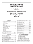
Figure 9.1 Connection Details ......................................................................................................... 27
Other Mantracourt Products ......................................................................................................... 28
1
Mantracourt Electronics Limited SGA/A & SGA/D User Manual
Chapter 1 Introduction to SGA/A & SGA/D
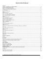
The Strain Gauge Amplifier SGA
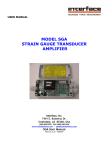
The SGA is a Strain Gauge Amplifier, converting a strain gauge input to a voltage or current output – otherwise
known as a Signal Conditioner.
The SGA provides a wide range of signal conditioning for Strain Gauges, Load Cells, Pressure and Torque
transducers.
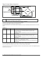
Figure 1.1 SGA Signal Conditioner
Inputs
Load Cells
Strain Gauges
Torque Transducers
Pressure Transducers
POWER
SUPPLY
STRAIN
GAUGE
AMPLIFIER
110/230 V AC
18-24V DC
INPUT
OUTPUT
±10V
±5V
0-5V
0-20mA
4-20mA
Offered in two versions, the SGA/A for 110/230V AC or 18-24V DC operation and the SGA/D which is DC powered
only.
A further powering option is available; the IS1224 module comprises a DC-DC converter enabling the SGA to be
powered from 9-36V DC. See Figure2.3 for details.
The ISS1224 can only be fitted to the SGA/D as it occupies the same space as the mains transformer in the SGA/A.
The SGA/A however, is isolated when AC powered by virtue of its mains transformer.
Transducer SENSITIVITY of between 0.1mV/V and 30mV/V are possible.
This is achieved by a combination of gain (span) DIP switches and associated fine adjustment by a potentiometer.
Similarly, transducer zero OFFSET and SCALE DEAD BAND of up to 79% can be compensated for in the module.
This is achieved again by a combination of zero DIP switches and associated fine adjustment by a potentiometer.
The module has built-in FILTERS to cancel the field effects of vibration, agitation and electrically noisy
environment.
The on-board low pass filter can be switched in and adjusted (from 1Hz to 5kHz) using a series of DIP switches.
A wide range of proportional output options for currents and voltages can be configured by DIP switch settings.
Both the AC and DC versions are based on a common board and are mounted in an IP65 (NEMA 4X) ABS case.
The SGA is a single channel signal conditioner but can supply sufficient excitation current to supply four 350 Ohm
load cells connected in parallel. The resulting output is the average of the individual cells.
An optional SGABCM bridge completion module is available to facilitate connecting half and quarter bridges to the
SGA – see Chapter 5 for details.
Mantracourt Electronics Limited SGA/A & SGA/D User Manual
2
Chapter 2 Installing the SGA/A & SGA/D
Pre Installation
See Specification details in Chapter 10 for details of Environmental Approvals.
Carefully remove the SGA/A unit from its packing. Check that the unit is complete and undamaged.
The SGA/A & SGA/D units can operated in any industrial environment providing the following limits are not
exceeded
Operating Temperature
Humidity
Storage temperature
-10 ºC to +50 ºC
95% non condensing
-20 ºC to +70 ºC
While the unit is sealed to IP65 (NEMA 4X) it is advisable to follow the following installation practice where possible
• Minimise vibration.
• Do not mount next to strong electrical fields (transformers, power cables)
• Ensure easy access to interior of the module
• Install electrical protection device, as the unit is not internally fused.
• Always ensure the lid is properly fitted and all 4 screws tightened.
• Always ensure the cable gland is sealing against the cable to maintain the IP (NEMA) rating.
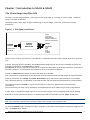
Figure 2.1 Dimensions
The 4 screws for the lid are captive and must be tightened to maintain the seal.
The 4.5mm (0.18”) holes for the mounting screws in the base are directly behind the screws for the lid.
The box must not be drilled as this would invalidate the IP rating
Allow sufficient space at both sides for the cable entry.
The Nylon 66 M16 cable glands are designed for ROUND cables.
The waterproof entry and strain relief will seal to a higher rating than the enclosure.
Cable diameter should be between 4mm (0.16”) and 7mm (0.27”)
3
Mantracourt Electronics Limited SGA/A & SGA/D User Manual
Cabling
Power Connection
Two power supply options are available
SGA/A:
220/230VAC, 50/60Hz
110/120VAC, 50/60Hz
5W Max.
SGA/A & SGA/D:
NOTE:
18-24V DC, 5W (approx. 150mA fully loaded)
The SGA/A can be powered from AC or DC sources whichever is available.
It is also possible to connect BOTH AC and DC simultaneously for security of power
supply.
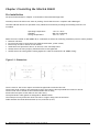
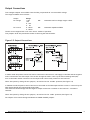
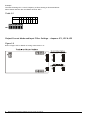
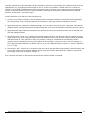
Figure 2.2 Power Connection
220-230 V AC
110 - 120 V AC
L
L
N
N
J3
18 -24 V DC
+ J3
J1
Standard mains 2 or 3 core cable PVC sheathed (unshielded) cable will suffice for the power.
NOTE:
Connect the appropriate power to the SGA. For AC powering observe the correct
transformer jumper connections as shown in Figure 2.2 above.
(This diagram is also provided inside the lid).
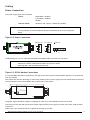
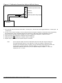
Figure 2.3 IS1224 Module Connections
To accommodate automotive installations, the SGA can be fitted with an IS1224 module enabling it to be powered
from 9 to 36V DC.
This module also has the advantage of electrically isolating the DC power supply from the measurement electronics
which minimises errors and instability due to earth loops in the system.
J1
+
9-36V
DC
IS1224 Module
J2
The power supply should be capable of supplying at least 1A for 12V installations and 0.5A for 24V.
Connections to the SGA/A & SGA/D input/output signal and the power supply are made via 2.5mm² field terminal
connectors.
Cable entry in the cased versions is via glands in the ends of the case.
Mantracourt Electronics Limited SGA/A & SGA/D User Manual
4
Figure 2.4 Input (Sensor) Connections
NOTE:
Strain Excite is the Excitation to the transducer.
Strain Input is the Signal from the transducer.
The Ref 5V/2.5V is generated internally and used for calibration
The cable connecting the sensor to the SGA should be shielded.
This typical cable data is provided for information only.
The cable should have 2 x twin twisted cables. Ideally with each pair individually shielded and with an overall
shield.
Table 2.1
Country
UK
Supplier
Farnell
Part No
148-539
UK
Farnell
585-646
UK
RS
367-533
Description
Individually shielded twisted multipair cable (7/0.25mm)- 2 pair
Tinned copper drain. Individually shielded in polyester tape.
Diameter: 4.19 mm
Impedance: 54 Ohms: Capacitance/m: core to core 115 pF & core to
shield 203 pF
Individually shielded twisted multipair cable (7/0.25mm)- 3 pair
Tinned copper drain. Individually shielded in polyester tape.
Diameter: 6.86 mm
Impedance: 62 Ohms: Capacitance/m: core to core 98 pF & core to
shield 180 pF
Braided shielded twisted multipair cable (7/0.2mm)- 1 pair
Miniature- twin -round Diameter: 4.8 mm
Impedance: 62 Ohms: Capacitance/m: core to core 120 pF & core to
shield 210 pF
If possible segregate the signal cable from Power Cables; allow a 1 metre (3 feet) distance from such cables.
Do not run signal cables parallel to power cables. Cross such cables at right angles.
The ground connection conductor should have sufficient cross-sectional area to ensure a low impedance path to
attenuate RF interference.
5
Mantracourt Electronics Limited SGA/A & SGA/D User Manual
Output Connections
Two analogue outputs are available from the SGA, proportional DC current and DC voltage.
The ranges available are as follows: Output
DC voltage
DC current
Range
±10V
±5V
0 - 10V
0 - 5V
0 - 20mA
4 - 20mA
NB:
Maximum Load on voltage ranges is 2mA.
NB:
Maximum impedance 500R.
The DC current support both ‘sink’ and ‘source’ modes of operation.
Two jumpers JP1 & JP2 provide the means of selecting the desired mode.
Figure 2.5 Output Connections
In ‘Sink’ mode the positive end of the load is connected to the internal +15V supply on the SGA and the negative
end is connected to the SGA output. The current through the load is ‘sunk’ by the SGA towards ground (0V).
N.B. In this mode neither connection to the output load is electrically common to the load cell.
Select this option by fitting the two jumpers, JP1 and JP2 to the ‘outside’ positions (See Figure 3.2)
In ‘Source’ mode the positive end of the load is connected to the SGA output and the current is ‘sourced’ by the
SGA output through the load towards ground (0V).
This mode has the advantage that the negative output connection is common to the load cell ‘- Excitation’
terminal.
Select this option by fitting the two jumpers, JP1 and JP2 to the ‘inside’ positions (See Figure 3.2)
See Chapter 3 for switch settings and details of SINK & SOURCE jumpers.
Mantracourt Electronics Limited SGA/A & SGA/D User Manual
6
Chapter 3 Switch Settings
Switch Positions
e.g. the switches in Figure 3.1 are depicted as ALL ON.
Figure 3.1 Output Settings–Switch 4
Use switch 4 to select the required output and, if
required, the low pass filter and 5V Excitation.
(See Tables 3.1 and 3.2)
Table 3.1 Output Option
Output Option
Input Range
4-20mA
0 - 20mA
4-20mA
0 - 20mA
0 - 10V
0 - 5V
±10V
±5V
+ Full Scale
20mA
20mA
20mA
20mA
10V
5V
10V
5V
↑
↑
↑
↑
↑
↑
↑
↑
↑
0
4mA
0mA
12mA
10mA
5V
2.5V
0V
0V
↓
↓
↓
↓
↓
↓
↓
- Full Scale
n/a
n/a
4mA Note 1 0mA Note 1
0V
0V
-10V
-5V
N.B.
Full scale output on the voltage ranges is achieved with a bi-polar (±) input
Note 1 Negative inputs can be accommodated on the current (mA) output ranges by setting the ‘Zero’ switch SW2
to +50% (Table 3.8) and setting SW1 to twice the required mV/V setting (Table 3.6).
Table 3.2 Switch 4
Analogue Output and Excitation Voltage Options - SW4
SW4
±10V
±5V
0-10V
0-5V
0-20mA
4-20mA
Filter out
Filter in
10V Exc
5V Exc
1
0↓
0↓
0↓
1↑
X
X
X
X
X
X
Switch settings
Important:
7
2
0↓
1↑
1↑
1↑
X
X
X
X
X
X
3
0↓
0↓
1↑
1↑
X
X
X
X
X
X
4
X
X
X
X
0↓
1↑
X
X
X
X
5
X
X
X
X
0↓
1↑
X
X
X
X
6
1↑=Filter in
1↑=Filter in
1↑=Filter in
1↑=Filter in
1↑=Filter in
1↑=Filter in
0↓
1↑
1↑=Filter in
1↑=Filter in
7
1↑Filter out
1↑Filter out
1↑Filter out
1↑Filter out
1↑Filter out
1↑Filter out
1↑
0↓
1↑Filter out
1↑Filter out
1↑=10V
1↑=10V
1↑=10V
1↑=10V
1↑=10V
1↑=10V
1↑=10V
1↑=10V
8
Exc 0↓=5V
Exc 0↓=5V
Exc 0↓=5V
Exc 0↓=5V
Exc 0↓=5V
Exc 0↓=5V
Exc 0↓=5V
Exc 0↓=5V
1↑
0↓
Exc
Exc
Exc
Exc
Exc
Exc
Exc
Exc
(0 = Off 1 = On X = Don’t Care)
Low pass filtering is switched into operation by setting SW4/6 ‘ON’↑ and SW4/7 ‘OFF’↓.
Reverse these settings to bypass the filter.
It should be noted that either one of these switches MUST be on but not BOTH
Mantracourt Electronics Limited SGA/A & SGA/D User Manual
Example: - 0-10 Volt output with no filter required.
Table 3.3
SW4
0-10V
SW4
1
0
↓
2
1
↑
3
1
↑
4
X
5
X
6
0
↓
7
1
↑
8
X
tsrrsssrst
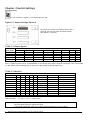
Output Filter Settings –Switch 3
The SGA incorporates a second order (-12dB/oct) low pass filter which can be switched in to improve the
performance and output signal quality in electrically noisy environments.
It can also be used to reduce the effects of high frequency fluctuations in the load or applied force to the load cell.
The cut off frequency of the filter is set by the DIP switch SW3 as illustrated in the table below
Table 3.4 Switch 3
SW3
1Hz
5Hz
10Hz
50Hz
100Hz
500Hz
800Hz
1kHz
5kHz
1
0
↓
1
↑
1
↑
1
↑
0
↓
1
↑
2
0
↓
0
↓
1
↑
1
↑
0
↓
0
↓
3
0
↓
0
↓
0
↓
1
↑
0
↓
0
↓
1
↑
1
↑
1
↑
1
↑
0
↓
1
↑
4
5
0
0
↓
↓
0
0
↓
↓
0
1
↓
↑
1
1
↑
↑
0
0
↓
↓
0
0
↓
↓
see note**
0
1
↓
↑
1
1
↑
↑
6
0
↓
1
↑
1
↑
1
↑
0
↓
1
↑
7
1
↑
1
↑
1
↑
1
↑
0
↓
0
↓
8
1
↑
1
↑
1
↑
1
↑
0
↓
0
↓
1
↑
1
↑
0
↓
0
↓
0
↓
0
↓
** Note:
A SECONDARY low pass filter, with a cut off frequency of 800Hz, can be switched into the SGA input by fitting a
link to JP3 (see Figure 3.2)
Important:
Low pass filtering is switched into operation by setting SW4/6 ‘ON’↑ and SW4/7
‘OFF’↓. Reverse these settings to bypass the filter.
It should be noted that either one of these switches MUST be on but not BOTH
Mantracourt Electronics Limited SGA/A & SGA/D User Manual
8
Example:The Switch Settings for a cut-off frequency of 50 Hz setting is illustrated below.
Note: SW4/6 must be ‘ON’ and SW4/7 must be ‘OFF’.
Table 3.5
SW3
50Hz
SW3
1 2 3 4 5 6 7 8
1 1 1 1 1 1 1 1
↑ ↑ ↑ ↑ ↑ ↑ ↑ ↑
trrrrrrrrt
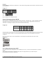
Output Current Mode and Input Filter Settings – Jumpers JP1, JP2 & JP3
Figure 3.2
Refer to Figure 2.5 for details of wiring connections to J1.
9
Mantracourt Electronics Limited SGA/A & SGA/D User Manual
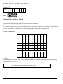
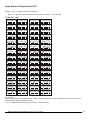
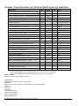
Span (Gain) Setting Switch SW1
Ranges 1 to 60 – from 0.06 mV/V to 30.30 mV/V
↑ = ON (1) ↓ = OFF (0). SW1/8 switches on the shunt cal function – see Table 3.8
Table 3.6 – SW1
1
0.06 mV/V
2
0.11 mV/V
3
0.17 mV/V
4
0.23 mV/V
12345678 12345678 12345678 12345678
5
0.28 mV/V
x
x
x
6
0.31 mV/V
7
0.34 mV/V
x
8
0.39 mV/V
12345678 12345678 12345678 12345678
9
0.44 mV/V
x
x
x
10
0.50 mV/V
11
0.55 mV/V
x
12
0.60 mV/V
12345678 12345678 12345678 12345678
0.61 mV/V
x
x
x
13
14
0.65 mV/V
15
0.70 mV/V
x
16
0.75 mV/V
12345678 12345678 12345678 12345678
0.75 mV/V
x
x
x
17
18
0.80 mV/V
19
0.91 mV/V
x
20
1.20 mV/V
12345678 12345678 12345678 12345678
1.41 mV/V
x
x
x
21
22
1.49 mV/V
23
1.78 mV/V
x
24
1.99 mV/V
12345678 12345678 12345678 12345678
25
2.07 mV/V
26
2.35 mV/V
x
x
x
x
27
2.49 mV/V
28
2.63 mV/V
12345678 12345678 12345678 12345678
29
2.91 mV/V
30
2.95 mV/V
x
x
x
x
31
3.19 mV/V
32
3.35 mV/V
12345678 12345678 12345678 12345678
33
3.46 mV/V
34
3.72 mV/V
x
x
x
x
35
3.73 mV/V
36
4.00 mV/V
12345678 12345678 12345678 12345678
37
4.00 mV/V
38
4.05 mV/V
x
x
x
x
39
4.26 mV/V
40
4.36 mV/V
12345678 12345678 12345678 12345678
4.63 mV/V
42
4.89 mV/V
x
x
x
x
41
43
5.12 mV/V
44
5.34 mV/V
12345678 12345678 12345678 12345678
5.54 mV/V
46
5.72 mV/V
x
x
x
x
45
47
7.50 mV/V
48
10.50 mV/V
12345678 12345678 12345678 12345678
13.20 mV/V
50
15.60 mV/V
x
x
x
x
49
51
17.80 mV/V
52
19.70 mV/V
12345678 12345678 12345678 12345678
53
21.50 mV/V
54
23.10 mV/V
x
x
x
x
55
24.60 mV/V
56
25.90 mV/V
12345678 12345678 12345678 12345678
57
27.10 mV/V
58
28.30 mV/V
x
x
x
x
59
29.30 mV/V
60
30.30 mV/V
12345678 12345678 12345678 12345678
x
x
x
x
Please Note:
When using 5V Excitation (SW4 switch 8 = OFF), divide the transducer's mV/V output by two and set SW1 to the
nearest setting shown in table 3.6 above
e.g. for 2.5mV/V with 5V excitation choose the 1.2mV/V setting
Mantracourt Electronics Limited SGA/A & SGA/D User Manual
10
Example:A strain gauge has a sensitivity of 2.809 mV /V - Select Switch Setting number 28 from Table 3.6 and fine tune with
potentiometer PI
Table 3.7
SW1
2.63 mV/V
SW1
1 2 3 4 5 6 7 8
0 1 1 0 0 0 0 X
↓ ↑ ↑ ↓ ↓ ↓ ↓
tsrrssssst
Refer to Chapter 4 for calibration details.
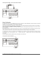
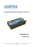
Shunt Calibration Switch SW1/8
SW1/8 connects a 120k 50ppm surface mount resistor across the ‘+Excitation’ and ‘+ Input’ terminals of the SGA.
This shunts one arm of the connected load cell to produce a known change in output which can be used for
calibration or checking the integrity of the load cell and associated wiring.
Table 3.8
SW1
Shunt Cal ON
1
x
2
x
3
x
4
x
5
x
6
x
7
x
Shunt Cal OFF
x
x
x
x
x
x
x
8
1
↑
0
↓
The 120k resistor can be taken out of circuit and replaced by a user defined leaded component by carefully cutting
the fine link as shown in Figure 3.3. Use the right hand pad and either of the left hand pads to fit the new
component.
The surface mount resistor can be reinstated by re-connecting the two pads either side of the cut link.
Figure 3.3
Zero (Offset) Setting Switch SW2
This offset can be used to compensate for the transducer zero error, to tare the scale dead load or to shift the
output.
These settings allow the user to calibrate a zero offset. The range allows for up to 79% of the span.
Potentiometer P2 provides fine adjustment.
11 Mantracourt Electronics Limited SGA/A & SGA/D User Manual
Table 3.9
SW2
%
1
+ ve Offset
2
- ve Offset
3
40%
4
20%
5
10%
6
5%
7
2%
8
1%
Example:An installation has a tare of 15 kg with a 200kg strain gauge which gives an output of 6.37mV/V at 10V excitation.
The tare equates to 7.5% (15/200). Set the switches to nearest % (5 + 2) and fine trim with Potentiometer P2.
The tare must be subtracted therefore the ‘- ve Offset’ switch SW2/2 should be ‘ON’.
The calibrated zero mV reading would be 4.78 mV i.e. 7.5% of 63.7mV
Table 3.10
SW2
7.5%
SW2
Note
1 2 3 4 5 6 7 8
0 1 0 0 0 1 1 0
↓ ↑ ↓ ↓ ↓ ↑ ↑ ↓
tsrsssrrst
SW2 /1 & 2 should never be 'ON ' together. Either one or other should be 'ON ' if an
offset is required; otherwise both switches should be 'OFF '.
Switch settings 3 to 8 are ADDITIVE. The offset value of each switch is added to give
a total offset of 78%.
Fine adjustment is provided by potentiometer P2.
Mantracourt Electronics Limited SGA/A & SGA/D User Manual
12
Chapter 4 Calibration
The SGA/A & SGA/D provides the excitation supply and signal conditioning to cater for a wide range of strain
gauges, load cells, pressure transducers or torque transducers.
Output
Select the analogue output range as detailed in Chapter 3, Figure 3.1, Tables 3.1 & 3.2 by means of SW4.
Zero Offset
Select the offset as detailed in Chapter 3, Table 3.9 by means of SW2.
Having selected the polarity and the offset nearest to that required with the switches use the fine potentiometer P2
to achieve the final setting.
Sensitivity
Select the sensitivity as detailed in Chapter 3, Table 3.6 by means of SW1.
Switches 1-4 of SW1 provide fine setting of the SGA sensitivity while switches 5-7 give coarse control.
This arrangement allows the SGA to cover a wide range of strain gauge sensitivities without sacrificing stability and
ease of set up.
Locate the required sensitivity in the table and set switches 1-7 of SW1 accordingly.
Potentiometer P1 provides fine trimming and range overlap to enable the SGA to be calibrated precisely to any
given value within its ranges.
Note 1
If the range is repeated in the table e.g. 4mV/V (4.0, 4.05 and 4.0 mV/V) choose the
setting which has the greatest number of switches 1-4 set to ‘off’ i.e. SW1 = [1000]
[000]. This will enable finer trimming to the final value using potentiometer PI.
The sensitivity settings shown in Table 3.6 assume that the load cell is fully loaded. The sensitivity settings can be
used to maximise the output when the full range of the load cell is not being used. Here are a couple of examples.
Example 1
Example 2
A 2.5mV/V load cell provides 10V for an l00Ib load. However it is never loaded above
50lb
The sensitivity setting can be set to 1.25 mV/V.
Table 3.6 /20 (1.20mV/V SW1 = [1101][000]
When a reduced output is required from a fully loaded transducer, use a less
sensitive switch setting.
For an 8 volt output from a fully loaded 2.5mV/V load cell use the 3.19mV/V setting
i.e. (10/8x2.5=3.125mV/V)
Table 3.6 /31 (1.20mV/V SW1 =[0010][000]
13 Mantracourt Electronics Limited SGA/A & SGA/D User Manual
The SGA/A & SGA/D can be calibrated with the transducer connected, provided that two calibration points can be
implemented, e.g. by applying known weights or forces. If this is not possible, a stable mV source or load cell
simulator can be used provided that the precise sensitivity (mV/V) and full range output (kg) of the transducer is
known. In this case the 'Ref (5V/2.5V)' output should be connected to 'Strain Input-' and the mV source applied
between ‘Strain Input+’ and ‘Strain Input-’.
Actual calibration is carried out in the following way:1. Set the correct switch settings on SW1 as described above using the transducer's calibration sheet supplied by
the manufacturer. This is normally specified as sensitivity or full range output and should be in mV/V
2. Apply the known low calibration conditions (weight, force or mV/V: this may be zero if required), and note the
analogue output, having ensured that the SW1 settings are correct for the transducer sensitivity as step 1 above.
3. Apply the known high calibration conditions (for optimum accuracy this should be at least 75% of full load) and
note the analogue output.
4. Use the fine trim control, P1, to obtain the required change in Volts or mA, between the two calibration points
(steps 2 and 3) e.g. If the required output at the low calibration point is 0V and the required output at the high
calibration point is 7.5V, adjust P1 in step 4 to produce a change of 7.5V between the calibration points.
Initially, the low calibration point may not produce 0V at the output. If this is the case, note the reading, e.g.
0.5V, apply the high calibration conditions and trim P1 for the required change in output i.e. trim the output for
0.5 + 7.5 = 8V.
5. Use the fine ‘Zero’ control, P2 in conjunction with the coarse switches SW2/3-8 and polarity switches SW2/1 and
2 to set the output to the required absolute values. Each switch within SW2 offsets the output by a particular
percentage of full scale as shown in Table 3.9
N.B. It may be necessary to repeat these steps until the required output is achieved.
Mantracourt Electronics Limited SGA/A & SGA/D User Manual
14
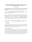
Figure 4.1 Calibration Connections Using a Millivolt Source
J2
-
Strain Excite (Excitation 10V/5V)
+
Shield (0V)
Ref (5V/2.5V)
-
Strain Input (Strain Gauge Output)
+
+
-
mV Source
1. The ‘Ref (5V/2.5V)’ should be connected to ‘Strain Input-’ and the mV source applied between ‘Strain Input+’ &
‘Strain Input-’
2. Set the correct switch settings on SW1 as described above using the transducer's calibration sheet supplied by
the manufacturer. This is normally specified as sensitivity or full range output and should be in mV/V
3. Ensure the Zero and Span switch settings are correct, as detailed in Chapter 3, Tables 3.6 & 3.9
4. Apply the known low calibration conditions and fine adjust P2.
5. Apply the known high calibration conditions and fine adjust P1
6. Repeat steps 3 and 4 until the required output is achieved.
Hint
If the required output at the low calibration point is 0V and the required output at
the high calibration point is 7.5V, adjust P1 in step 5 to produce a change of 7.5V
between the calibration points. Initially, the low calibration point may not produce 0V
at the output. If this is the case, note the reading, e.g. 0.5V, apply the high
calibration conditions and trim P1 for the required change in output, i.e. Trim the
output for 0.5 + 7.5 = 8V.
15 Mantracourt Electronics Limited SGA/A & SGA/D User Manual
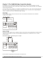
Chapter 5 The SGABCM Bridge Completion Module
The SGABCM is a retro-fit PCB which facilitates connecting a half or quarter-bridge strain gauge to the SGA.
Screw terminal connections accept a wide range of bridge completion resistor types and enable on-site installation
without soldering equipment.
Two high stability resistors (±5ppm/°C) are fitted to the SGABCM to form the ‘fixed’ arms of the bridge while the
user’s half or quarter-bridge strain gauge elements complete the circuit. In the latter case a ‘bridge completion’
resistor is required to form the full ‘Wheatstone bridge’ topology.
Half Bridge
The half-bridge is simply connected to the SGA via the screw terminals as shown below and no additional
components are required:
Rm S/C 24V S+
D
Ref Shld +EXC -EXC
S/Cal
- + Off
Loc Rem
R Tension
R Comp
R S/Cal
Quarter Bridge
The quarter-bridge, together with its completion resistor can be wired in two ways depending on whether the user
requires a positive output as a result of the strain gauge being subjected to a compression force or a tension
(stretching) force.
Rm S/C 24V S+
Rwire
Rwire
Sense
3-Wire Quarter Bridge - compression gives +ve output
D
Ref Shld +EXC -EXC
S/Cal
- + Off
Loc Rem
R Tension
R Comp
R S/Cal
Bridge completion
resistor
3-wire connection compensates for the resistance of the cable cores.
Mantracourt Electronics Limited SGA/A & SGA/D User Manual
16
Rm S/C 24V S+
Rwire
Rwire
Sense
3-Wire Quarter Bridge - tension gives positive output
D
Ref Shld +EXC -EXC
S/Cal
- + Off
Loc Rem
R Tension
R Comp
R S/Cal
Bridge completion
resistor
Shunt Calibration
An additional feature of the SGABCM allows the user to perform a ‘Shunt Calibration’ (shunt cal) test to check the
integrity of the strain gauge(s), wiring and SGA calibration.
This involves temporarily connecting a relatively high value resistor between the positive output of the bridge to
either the positive or negative excitation connections.
Screw terminals are provided for the resistor which should be scaled appropriately taking into account the strain
gauge impedance.
The resulting change in output when the shunt cal resistor is connected should be recorded and referred to when
future checks are performed. Any deviation outside tolerance limits will flag up a fault condition.
To implement the ‘shunt cal’ operation on the SGABCM a set of header pins are provided with a shorting link that
can be fitted in one of three positions: ‘Off’, ‘+’ (positive shift) and ‘–‘ (negative shift). These are clearly marked
on the PCB.
The shorting link should be parked in the ‘Off’ position for normal use.
Local positive shunt calibration
Rm S/C 24V S+
D
Ref Shld +EXC -EXC
S/Cal
- + Off
Loc Rem
R Tension
R Comp
R S/Cal
Shunt calibration
resistor
17 Mantracourt Electronics Limited SGA/A & SGA/D User Manual
Local negative shunt calibration
Rm S/C 24V S+
D
Ref Shld +EXC -EXC
S/Cal
- + Off
Loc Rem
R Tension
R Comp
R S/Cal
Shunt calibration
resistor
Remote Shunt Calibration
In addition, ‘Remote Shunt Cal’ can be performed by means of a N.O. 24V DC relay fitted to the module. The relay
supply can be situated some distance from the SGA and even be connected in parallel to several SGAs in a multiple
installation enabling them to be shunt cal’d simultaneously.
Remote positive shunt calibration
24V DC
Rm S/C 24V S+
D
Ref Shld +EXC -EXC
S/Cal
- + Off
Loc Rem
R Tension
R Comp
R S/Cal
Shunt calibration
resistor
The SGABCM can be supplied when ordering an SGA/A or D or ordered separately for retro-fitting to existing SGAs.
The SGABCM is compatible with all variants of the SGA i.e. SGA/A, SGA/D and SGAs fitted with the IS1224 isolated
DC power supply module.
Mantracourt Electronics Limited SGA/A & SGA/D User Manual
18
Chapter 6 Troubleshooting
1.
a)
b)
c)
d)
No output
Check power supply is present (LED is on).
Check the output connections are correct.
Check terminations (ensure insulation is not trapped in terminal, cable break etc.)
Check the sensor is connected (typically reading 350 Ohm across Strain Excite + and – and also
Strain Input + and – of J2) with the power off.
e) Check the Excitation voltage (J2) is at 10V DC
1.a For voltage output
a) Check V out+ and V out- terminals are wired
b) Check the load is connected and is not open or short circuited
c) Check SW4 settings are correct for Voltage Output see Chapter 3, Table 3.2
d) Check Span and Zero settings (SW1 and SW2)
1.b For current output
a) Check Isink+ and Isink- terminals are used for 'Sink' current output
b) Check Isource+ and Isource- terminals are used for 'Source' current output.
c) Check the load is connected and is not open circuit
d) Check load does not exceed 500 Ohms.
e) In 'Sink' mode check 15 V is present at +ve terminal of load.
f) In 'Source' mode check the -ve terminal of the load is connected to ground.
g) In 'Sink' mode check the load is isolated from the load cell (sensor) excitation.
h) In 'Source' mode check the -ve output is common to the -ve Excitation.
i) Check output SW 4 settings are correct for current see Chapter 3, Table 3.2
j) Check Span and Zero settings (SW1 and SW2) see Chapter 3, Table 3.6 & 3.9
2. Low Output
This is when an output is present but not of sufficient magnitude to meet the required value.
b) Check power supply is within specified limits (i.e. is not low)
c) Check the sensor is connected (typically reading 350 Ohm across Strain Excite + and – and also
Strain Input + and – of J2) with the power off.
d) Check the Excitation voltage (J2) is at 10V DC
e) Check the calibration. Incorrect setting of the calibration Span switches are the most common cause of low
output - particularly when associated with ± Voltage outputs. Refer to the calibration instructions in Chapter 4.
Refer to tutorial on the calibration set-up.
f) Check the Zero (offset) is correct for the sensor. This too is a common reason for low outputs.
3. High output
This is when an output is present but higher (in span or zero) than required.
b) Check the sensor is connected (typically reading 350 Ohm across Strain Excite + and – and also
Strain Input + and – of J2) with the power off.
c) Check the Excitation voltage (J2) is at 10V DC
d) Check the Zero (offset) is correct for the sensor. This is a common reason for high outputs where the offset is
either omitted or incorrect for the sensor. Refer to the calibration instructions in Chapter 4
e) Refer to tutorial on the calibration set-up
f) Check the calibration. Incorrect setting of the calibration span switches is the most common cause of high
output - particularly when associated with ± Voltage outputs.
19 Mantracourt Electronics Limited SGA/A & SGA/D User Manual
4. Unstable Output
This is when the output is unstable or varies. The cause could be (a) poor installation or (b) a noisy environment.
Poor Installation -This is when an output is present but higher or lower (in span or zero) than expected:
a) Check the installation for problems and repair where necessary
b) Poor termination
c) High resistance on cable leads
d) Low insulation impedance
e) Proximity to High Voltage Equipment – Transformers, Contactors, Motors etc.
Noisy Environmenta) Check if the source can be found and remove noise
b) Check the cable shielding and ensure it is correctly installed and terminated
5. Calibration
This section assumes that the unit is providing an output that is not stuck at top or bottom of the scale.
(See paragraphs 1 to 4 if this is the case)
Ensure you have the calibration set-up correctly installed i.e.mV source and output as required.
Ensure you are connected to the correct sensor and not to another adjacent unit.
Ensure you have the correct calibration data from the sensor manufacturer. This must include a certified table with
offset, zero and linearity.
Ensure the temperature and other environmental parameters are within specification and where necessary taken
into account when calibrating should such parameters have an effect on the calibration.
6. Fine Span (Gain) and Zero (Offset ) Adjustment Problems
If the adjustment cannot reach the maximum output desired then, check the tare is not too high.
If the potentiometer does not alter the output the unit must be repaired – remove from service.
It is always wise to check a known good SGA against the problem installation before rejecting the suspect SGA.
Mantracourt Electronics Limited SGA/A & SGA/D User Manual
20
Chapter 7 Product Care
A worn out component, excessive use in harsh environments, an overly zealous operator; regrettably some
circumstances necessitate repair.
At Mantracourt Electronics Ltd we can't guarantee that a product will never require repairing. We can, however,
promise a repair service of exceptional quality, one which is governed by a rigorous procedure.
Detailed below is our pledge to you: a defined set of ground rules and procedures to which we will adhere. All we
ask in return is that you assist us with our procedure, such that we can maintain our promise to you. Please note
that warranty repairs may not be available on overdue accounts, and that a strict interpretation of our conditions of
trading invalidates warranty claims where late payment has occurred.
Please refer to ‘Customer Repair Service Procedure’ document – contact your supplier for a copy.
In the unlikely event you have problems with the SGA module we would advise that you take the following
precautions:•
•
•
•
•
The unit is installed as instructed.
Recommended spares are kept in stock. We can assist.
Sufficient expertise available for first line maintenance.
Routine maintenance checks are performed – annually is recommended.
The necessary documentation for the product is available to the maintenance personnel.
We recommend you keep on file – as a minimum
• This Manual
• The settings of the switches and links on the SGA card
• The calibration figures for the attached sensors
• The instrument loop to which the output is connected
• A record of the ‘normal’ output – if applicable
• A maintenance record of the SGA
• A contact phone number from the supplier for assistance
21 Mantracourt Electronics Limited SGA/A & SGA/D User Manual
Chapter 8 Glossary
AWG
Background Noise
Bipolar
Bridge Resistance
Calibration
CMR
(Common-Mode
Rejection)
Common Mode Rejection
Ratio
Deadband / hysteresis
Drift
Dual Power supply
Excitation
Fine Adjustment
Full Bridge
Full Range Output
Gain
Ground
Input Impedance
Linearity
Load
Load Impedance
Load cell
Low Pass Filter
millivolt
American Wire Gauge.
The total noise floor from all sources of interference in a measurement
system, independent of the presence of a data signal. (See noise)
The ability of a signal conditioner to display either positive or negative
readings.
The resistance measured across the excitation terminals of a strain
gauge.
The process of adjusting an instrument or compiling a deviation chart so
that it’s reading can be correlated to the actual value being measured.
The ability of an instrument to eliminate the effect of AC or DC noise
between signal and ground. Normally expressed in dB at dc to 60 Hz. One
type of CMR is specified between SIG LO and PWR GND. In differential
meters, a second type of CMR is specified between SIG LO and ANA GND
(METER GND).
The ability of an instrument to reject interference from a common
voltage at its input terminals with relation to ground. Usually expressed
in db (decibels).
(Hysteresis) In a digital controller, there may be one switching point at
which the signal increases and another switching point at which the signal
decreases. The difference between the two switching points is hysterisis.
A change of a reading or a set point value over long periods due to
several factors including change in ambient temperature, time, and line
voltage.
The SGA/A can have a Dual Power Supply. An AC supply can be connected
along with a DC supply for additional security.
The external application of electrical voltage applied to a transducer for
normal operation.
The Zero and Span calibration have a Fine Adjustment to give accuracy to
the calibration. These are potentiometers P1 and P2 for span and zero
respectively.
A Wheatstone bridge configuration utilizing four active elements or strain
gauges.
The algebraic difference between the minimum output and maximum
output.
Gain is otherwise identified as SPAN. It relates to the proportional output
to the sensor input. Calibration of the SGA is determined by setting the
Gain (Span) and Offset (Zero).
The amount of amplification used in an electrical circuit.
1)The electrical neutral line having the same potential as the surrounding
ground. 2) The negative side of power supply. 3) Reference point for an
electrical system.
The resistance measured across the excitation terminals of a transducer.
The closeness of a calibration curve to a specified straight line. Linearity
is expressed as the maximum deviation of any calibration point on a
specified straight line during any one calibration cycle.
The electrical demand of a process expressed as power (watts), current
(amps) or resistance (ohms).
The impedance presented to the output terminals of a transducer by the
associated external circuitry.
The load cell is one of a series of Strain Gauge sensors that the SGA input
is designed to accept. (Torque Sensor, Pressure & temperature
transducers).
The SGA Module has a low pass filter to remove unwanted signals on the
output. This can be set to suit the installation, from DC to 5kHz.
One thousandth of a volt, 10-3 volts symbol mV.
Mantracourt Electronics Limited SGA/A & SGA/D User Manual
22
NEMA 4/ UL Type 4
Noise
Null
Offset
Potentiometer
Pressure Transducer
Proportional Outputs
Resolution
Sensing Element
Sensitivity
Signal Conditioner
Single card assembly
Span
Span Adjustment
Stability
Strain Gauge
Torque Transducer
Zero
Zero Adjustment
A standard from the National Electrical Manufacturers Association, which
defines enclosures, intended for indoor or outdoor use primarily to
provide a degree of protection against windblown dust and rain, splashing
water, and hose-directed water.
An unwanted electrical interference on the signal wires.
A condition, such as balance, which results in a minimum absolute value
of output.
Offset is otherwise identified as Zero. It relates to the proportional
output to the sensor input. Calibration of the SGA is determined by
setting the Offset (Zero) and Gain (Span).
Two potentiometers (variable resistors) are used in the SGA for fine
calibration.
The Pressure Transducer is one of a series of Strain Gauge sensors that
the SGA input is designed to accept. (Torque Sensor, Load Cell and
Temperature transducers).
The Voltage or Current outputs are calibrated to be directly proportional
to the input from the sensor. The output is, within the sensor limits,
taken as linear and no linearity compensation is required within the SGA.
The input corresponding to a one-unit change in the least significant digit
of the data acquisition /display equipment (Good resolution is not
necessarily equal to good accuracy.)
That part of the transducer, which reacts directly in response to the
input.
The minimum change in input signal to which an instrument can respond.
This is the relationship between the change in strain gauge output to the
level or magnitude of the SGA output
A circuit module that offsets attenuates, amplifies, linearises and/or
filters the signal for input to an A/D converter. A typical output signal
conditioning is 4 to 20 mA.
The SGA is essentially a Signal Conditioner –more specifically known as a
Strain Gauge Amplifier - in that it conditions (alters) the input signal from
a load cell to an electrical output
The SGA has only the one Printed Circuit Board assembly on which all the
components are mounted. The assembly is then mounted inside an
environmentally rugged enclosure.
Span is otherwise identified as GAIN. It relates to the proportional output
to the sensor input. Calibration of the SGA is determined by setting the
Span (Gain) and Zero (Offset).
The ability to adjust the gain of a process or strain meter so that a
specified display span in engineering units corresponds to a specified
signal span. For instance, a display span of 200°F may correspond to the
16 mA span of a 4-20 mA transmitter signal.
The quality of an instrument or sensor to maintain a consistent output
when a constant input is applied.
The strain gauge is a resistance bridge device where the bridge value
alters linearly and proportionally to the force exerted on it – be it
temperature, pressure, torque or load. The SGA is designed to convert
this change to a proportional electrical signal.
The Torque Transducer is one of a series of STRAIN GAUGE sensors that
the SGA input is designed to accept. (Torque Sensor, Load Cell and
Temperature transducers).
Zero is otherwise identified as Offset. It relates to the proportional
output to the sensor input. Calibration of the SGA is determined by
setting the Span (Gain) and Zero (Offset).
The ability to adjust the display of a process or strain meter so that zero
on the display corresponds to a non-zero signal, such as 4 mA, 10 mA, or
1 V dc.
23 Mantracourt Electronics Limited SGA/A & SGA/D User Manual
Zero Offset
Zero Suppression
The difference expressed in degrees between true zero and an indication
given by a measuring instrument. See Zero Suppression
The span of the SGA can be offset from zero (zero suppressed) such that
neither limit of the span will be zero. For example, an SGA which
measures a load of a 100kg span from 400kg to 500kg° is said to have
400kG zero suppression.
AC
DC
Hz
IP66
kHz
mA
mm
NEMA 4X
SC
SGA
V
mV
Alternating Current
Direct Current
Hertz (Frequency)
UK Environmental Specification
kiloHertz (Frequency)
milliamps
millimetres
US Environmental Specification
Signal Conditioner
Strain Gauge Amplifier
Volts
millivolts
Mantracourt Electronics Limited SGA/A & SGA/D User Manual
24
Chapter 9 Specifications for SGA/A & SGA/D Load Cell Amplifiers
Parameter
Min
Typical
Max
Units
-
110/230
-
V AC
Power supply dc: -
18
-
24
V DC (See note 1)
Power supply current dc: - (depends on loading)
50
90
200
mA
Bridge excitation (10V range)
9.75
10
10.25
V (See note 2)
Bridge excitation (5V range)
4.85
5
5.15
V (See note 2)
85
-
-
Bridge sensitivity (Switchable)
0.06
-
30
mV/V
Gain adjustment (Pot - fine adj.)
0.06
-
1.0
mV/V
Offset adjustment voltage output (Pot - fine adj.)
-
±2.8
-
%FR
Offset adjustment current output (Pot - fine adj.)
-
±5.5
-
%FR
±1.25
-
±79
%FR
Output load (Voltage output)
-
-
2
mA
Output load (Current output)
0
-
500
DC
-
6
kHz
Filter cut-off (Switchable ranges)
1
-
5000
Hz
Zero temperature coefficient (@2.5mV/V)
-
0.002
0.009
%/ºC@ 2.5mV/V FR
Span temperature coefficient
-
0.007
0.01
%/ºC
Linearity
-
0.03
-
%FR
Gain stability -1st 1000 Hours
-
0.2
-
%FR
0.1
-
%FR
Power supply (SGA/A):- (110/230Vac) 50 - 60Hz
Bridge resistance
Offset adjustment (Switchable - coarse adj.)
Bandwidth (No filter and > 2mV/V)
Gain stability - 2nd 1000 Hours
Ohms (See note 3)
Ohms
90 day Offset stability
-
3.3
-
uV
Output load stability gain (0 - 100%)
-
-
0.01
%FR
Output load stability offset (0 - 100%)
-
-
0.01
%FR
Power supply rejection gain (0 - 100%)
-
-
0.01
%FR
Power supply rejection offset (0 - 100%)
-
-
0.01
%FR
Operating temperature range
-10
-
50
ºC
Storage temperature range
-20
-
70
ºC
Humidity
95
%
Note 1: 18V max at full load (four 350 Ohm Load Cells connected in parallel @ 10V excitation)
Note 2: Switch SW4/8 on for 10V excitation, off for 5V excitation (Table 3.2)
Note 3: Four 350 Ohm Load Cells connected in parallel @ 10V excitation
Output options:
±10V, ±5V, 0-10V, 0-5V, 0-20mA, 4-20mA
Connections:
Field screw terminals - 2.5mm² rising clamp.
Enclosure:
ABS case 164 x 84 x 55 sealed to IP65 fitted with 3 off cable glands.
Controls:
Gain pot
Offset pot
Coarse gain switches
Coarse offset switches
Filter cut-off switches
Output mode switch
25 Mantracourt Electronics Limited SGA/A & SGA/D User Manual
CE Approvals
European EMC Directive
2004/108/EC
BS EN 61326-1:2006
BS EN 61326-2-3:2006
Low Voltage Directive
2006/95/EC
BS EN 61010-1:2001
Rated for Basic Insulation
Normal Condition
Pollution Degree 2
Permanently Connected
Insulation Category lll
Warranty
All SGA products from Mantracourt Electronics Ltd., ('Mantracourt') are warranted against defective material and
workmanship for a period of (3) three years from the date of dispatch.
If the 'Mantracourt' product you purchase appears to have a defect in material or workmanship or fails during
normal use within the period, please contact your Distributor, who will assist you in resolving the problem. If it is
necessary to return the product to 'Mantracourt' please include a note stating name, company, address, phone
number and a detailed description of the problem. Also, please indicate if it is a warranty repair.
The sender is responsible for shipping charges, freight insurance and proper packaging to prevent breakage in
transit.
'Mantracourt' warranty does not apply to defects resulting from action of the buyer such as mishandling, improper
interfacing, operation outside of design limits, improper repair or unauthorised modification.
No other warranties are expressed or implied. 'Mantracourt' specifically disclaims any implied warranties of
merchantability or fitness for a specific purpose. The remedies outlined above are the buyer’s only remedies.
'Mantracourt' will not be liable for direct, indirect, special, incidental or consequential damages whether based on
the contract, tort or other legal theory.
Any corrective maintenance required after the warranty period should be performed by 'Mantracourt' approved
personnel only.
Mantracourt Electronics Limited SGA/A & SGA/D User Manual
26
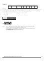
N
L
J3
2
0
1
1
1
x
x
x
x
3
0
0
1
1
x
x
x
x
4
x
x
x
x
0
1
x
x
5 6
x
x
x
x
0
1
x 0
x 1
567
000
0.31
0.61
0.91
1.20
1.49
1.78
2.07
2.35
2.63
2.91
3.19
3.46
3.73
4.00
4.26
567
111
0.75
1.41
1.99
2.49
2.95
3.35
3.72
4.05
4.36
4.63
4.89
5.12
5.34
5.54
5.72
567
110
4.0
7.5
10.5
13.2
15.6
17.8
19.7
21.5
23.1
24.6
25.9
27.1
28.3
29.3
30.3
J1
Sw3
1 2 3 4 5 6 7 8
27 Mantracourt Electronics Limited SGA/A & SGA/D User Manual
-
Sw2 1 2 3 4 5 6 7 8
% +
40 20 10 5 2 1
1 2 3 4 5 6 7 8
Sw8
On
Off
Span (Gain) Sw1 Shunt cal.
Shunt cal. resistor
1 2 3 4 5 6 7 8
Filter
1 2 3 4 5 6 7 8 5V Exc
Analogue Output Sw4
P2 Zero Zero (Offset) Sw2
7
1=No Filter
1=No Filter
1=No Filter
1=No Filter
1=No Filter
1=No Filter
1
0
Sw1 Span (Gain) mV/V
1
0
0
0
1
x
x
x
Filter in x
Sw4 Analogue Output
Sw4
+/- 10V
+/- 5V
0-10V
0-5V
0-20mA
4-20mA
1 2 3 4 567
001
1 = On 0 1 1 1 0.06
0 = Off 1 0 1 1 0.11
0 0 1 1 0.17
Sw3 Filter
1 1 0 1 0.23
Sw3 1 2 3 4 5 6 7 8 0 1 0 1 0.28
1Hz 0 0 0 0 0 0 1 1 1 0 0 1 0.34
5Hz 1 0 0 0 0 1 1 1 0 0 0 1 0.39
1 1 1 0 0.44
10Hz 1 1 0 0 1 1 1 1 0 1 1 0 0.50
50Hz 1 1 1 1 1 1 1 1 1 0 1 0 0.55
100Hz 0 0 0 0 0 0 0 0 0 0 1 0 0.60
1 1 0 0 0.65
500Hz 1 0 0 0 0 1 0 0 0
1 0 0 0.70
1kHz 1 1 0 0 1 1 0 0 1 0 0 0 0.75
0
0
0 0 0.80
5kHz 1 1 1 1 1 1 0 0
L
J3
N
110-120V
L
J3
N
SGA/A
220-230V
P1
Jp1
Jp2
Jp3
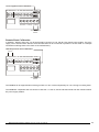
DC power +
DC power V out +
I source -/V out I sink +
I source +/I sink -
- Strain Excite
+ (5V/10V)
Screen (0V)
Ref (2.5V/5V)
- Strain Input
+ Strain Input
Screen
+ Output
+
+
‘Source’ mode current output
(500 Ohms max) N.B.common
to PSU negative & strain gauge
screen
‘Sink’ mode current output
(500 Ohms max) N.B.not
common to PSU negative
or strain gauge screen
Voltage output (2mA max)
{
- Excitation
Strain gauge
+ Excitation
- Output
Nominally at 5V (2.5V if using 5V
excitation)
Ref: Connect to ‘Strain Input +’ & ‘-’
to check zero.
If using a mV source for calibration
connect ‘Ref’ to ‘Strain Input -’
+
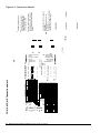
SGA/A & SGA/D Connection details
Figure 9.1 Connection Details
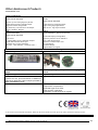
Other Mantracourt Products
mantracourt.com
Signal Conditioning
SGA
STRAIN GAUGE AMPLIFIER
ICA
IN-CELL
STRAIN GAUGE AMPLIFIER
Connect up to 4 strain gauges in parallel
Proportional mA and/or Voltage output
Simple DIL switch configuration
Set Sensitivity, Low Pass Filter and Output
Simple - Reliable - Rugged
LCA
IN-LINE INTELLIGENT
STRAIN GAUGE AMPLIFIER
2 Set Points
4 to 20mA AND 0 to 10 V (isolated) outputs
RS 232/485 Communications port
On-Board easy to use Programmer
Auto tare – Auto calibrate – and much more …..
DSC The Digital Strain Card
Proportional mA or Voltage output
Single strain gauge applications
small in size – big on specification
ADW15
72 mm DIN Module – Display & Controller
10 mm LED Display (Configurable)
Sensitivity from 0.5 mV to 200 mV/V
10 V @ 150 mA Excitation
Isolated I/O 100ms sample rate
Set Point Relays
4 to 20mA Output
Programmable via keypad
Fieldbus Connectivity In Two Excellent Packages
DCell The ‘in-cell’ Digital Strain Puck
Mount this package adjacent to the strain
gauge
Plug-in-and-go-sensor
Integrate the electronics with the load cell,
remove the cost, space and bother of additional
electronics and have a direct output provided in
REAL ENGINEERING UNITS.
Mount this package directly into the strain gauge
pocket
High accuracy
A quantum leap in the quality of measurement.
Accuracy (1 part in half a million)
Temperature compensated
Unwanted Signal noise filter
Sensor specific calibration
Elimination of induced noise on signals
In the interests of continued product development, Mantracourt Electronics Limited reserves the right to alter product specifications without prior notice.
Code No. 517-150
Mantracourt Electronics Limited SGA/A & SGA/D User Manual
Issue 4.0
30.04.15
28