1
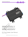
Serial Data Logger User Manual SERIAL DATA LOGGER – USER MANUAL Document Revision History Date Revision Comments Nov 15, 2011 V1.0 Created. Reference Documents The following documents provide useful background and context. Number/Author Document Title Location 1.0.04/VT EVision User’s Manual “evision_manual v1.0.04.pdf” COPYRIGHT © 2011 METRIC MIND CORPORATION II SERIAL DATA LOGGER – USER MANUAL TABLE OF CONTENTS Serial Data Logger ......................................................................................................................... i User Manual ................................................................................................................................... i Document Revision History ................................................................................................................... ii Reference Documents ............................................................................................................................. ii 1 2 3 Introduction ............................................................................................................................ 4 1.1 Overview ..................................................................................................................................... 4 1.2 Components ................................................................................................................................ 4 Connectiong the Data Logger to an EVision System ......................................................... 5 2.1 Cable Wiring .............................................................................................................................. 5 2.2 Connection Sequence ................................................................................................................ 5 Collecting EVision Data Logs............................................................................................... 6 3.1 Powering Up the Data Logger ................................................................................................. 6 3.2 Starting a New Logging Session .............................................................................................. 6 3.3 Ending a Logging Session ......................................................................................................... 6 4 Reading SD Card Log Data on a PC ................................................................................... 7 5 Error Conditions .................................................................................................................... 8 6 5.1 Error State .................................................................................................................................. 8 5.2 Determining the Error Code.................................................................................................... 8 5.3 Error Code List.......................................................................................................................... 9 Specifications ........................................................................................................................ 10 6.1 Environmental Specifications ................................................................................................ 10 6.2 Power Specification ................................................................................................................. 10 6.3 Physical Specifications ............................................................................................................ 10 6.4 Serial Data Interface Specification........................................................................................ 10 COPYRIGHT © 2011 METRIC MIND CORPORATION III SERIAL DATA LOGGER – USER MANUAL 1 1.1 Introduction Overview Thank you for purchasing the Metric Mind Corporation Serial Data Logger product. The Data Logger works directly with the Metric Mind EVision instrumentation system to capture and store data exported from the EVision system. EVision streams data out through an isolated RS-232 interface, which is also used for system configuration. Exported data can be captured with a portable PC, however keeping the PC active while driving is often inconvenient. The Data Logger solves this dilemma, and also allows data to be collected during both drive, quiescent and charging periods. The Data Logger stores the captured data on an SD memory card, which can be easily read by a PC, for review and analysis. The Data Logger connects to the same DB-9 connector used to configure the EVision unit. The Data Logger requires two additional wires to be connected between the EVision main unit and the DB-9 connector – see the Wiring section of this manual for details on those additional connections. 1.2 Components The following picture shows the major components of the Data Logger unit. The Data Logger male DB-9 connector connects to the EVision main unit female DB-9 connector. COPYRIGHT © 2011 METRIC MIND CORPORATION 4 SERIAL DATA LOGGER – USER MANUAL 2 Connectiong the Data Logger to an EVision System 2.1 Cable Wiring The table below shows the necessary wiring connections between the EVision 35 pin Ampseal connector and the female DB-9 connector. Signal EVision 35-pin Connector Female DB-9 Connector RS 232 GND 11 5 RS 232 data out 12 2 RS 232 data in 23 3 - Power OUT 14 9 + Power OUT 25 1 Note: The first three wires may already be in place if you have previously wired a DB-9 connector to the EVision unit for configuration or monitoring purposes. If so, those three wires can remain in place, just add the last two connections to provide power from the EVision main unit to the Data Logger. 2.2 Connection Sequence When connecting the Data Logger to the female DB-9 connector from the EVision unit, take care to connect the ground side first (pins 5 and 9 of the DB-9 connector). Do this by tilting the DB-9 connector slightly so that pins 5 and 9 connect first as the connectors are mated. This ensures that the Data Logger powers up correctly without affecting the current state of the EVision unit. In some vehicle configurations plugging the DB-9 connectors together in a different connection order may cause the EVision unit to reset. If this occurs the EVision display will go blank for a few seconds and then resume once the unit has finished the restart sequence. COPYRIGHT © 2011 METRIC MIND CORPORATION 5 SERIAL DATA LOGGER – USER MANUAL 3 Collecting EVision Data Logs The sections below describe the process and indications for performing a logging sequence. Once the Data Logger is powered up, the sequence is: Depress the pushbutton to start logging Depress the pushbutton again to stop logging 3.1 Powering Up the Data Logger Power up the Data Logger by connecting it to the female DB-9 connector that is wired to the EVision unit. Follow the connection sequence described in Section 2.2. When successfully powered up, the blue light on the Data Logger flashes slowly and the red light is off. 3.2 Starting a New Logging Session To start a new logging session: Insert an SD card into the SD card slot on the side of the Data Logger. Insert the edge of the card with the gold connector pads first, with the gold pads facing up. Continue inserting the card until the spring loaded latch actuates to hold the card in place. Note: The maximum capacity SD card supported by the Data Logger is 2 GB. Depress and hold the pushbutton until the blue light stops flashing. Release the pushbutton. The Data Logger is now in logging mode and will remain in logging mode as long as the EVision unit is powered. EVision exports data continuously, across all vehicle states, so the Data Logger can collect data continuously through drive, quiescent (parked) and charge cycles. During logging, the blue light on the Data Logger will flash briefly every one to two seconds as data is written to the SD card. 3.3 Ending a Logging Session To end a logging session: Depress the pushbutton. Release the pushbutton. The blue light will stop flashing and the red light will begin flashing slowly. The final logged data is written to the log file on the SD card – see Section 4 for details. To start another logging session, power off the Data Logger by disconnecting it from the DB-9 connector and then reconnecting. Follow the steps described in Section 3.2 to start data logging. COPYRIGHT © 2011 METRIC MIND CORPORATION 6 SERIAL DATA LOGGER – USER MANUAL 4 Reading SD Card Log Data on a PC The Data Logger stores logged data into files on the SD card. Each logging session produces one log file. The log files are created in the root directory of the SD card. The log file names are of the form EVLOG001.TXT. The log files are created in sequential order, as in EVLOG001.TXT, EVLOG002.TXT up to a maximum of 250 files, with the last file being named EVLOG250.TXT. Note: The Data Logger creates files in strict sequential order. If the files EVLOG001.TXT, EVLOG002.TXT and EVLOG004.TXT already exist on the SD card, the next logging session will be placed in a file named EVLOG003.TXT. To access the log files, insert the SD card into a PC and copy the log file or files to the PC and then delete the log file or files from the SD card. This ensures that the SD card always has the maximum available space for recording new logging sessions. Use care when copying the log file from the SD card to the PC to ensure that previous log files with the same name are not overwritten. The recommended process is to rename the log files once they have been copied to the PC. You may also need to trim the data lines near the beginning and end of the file to remove any partial lines that may have been captured. Note: The file date and time information for the log files is NOT set in the SD card directory. Examine the data inside the log file to determine the time order based on the date and time reported within the EVision data stream. A section of a sample EVision log file is shown below. $RV,17:32:03,Nov-13-2011,392,+0.00,+0.00,+0.00,+0.00,+0.00,+00.0,+00.0 $CV,17:32:03,Nov-13-2011,97,+316.42,+158.35,+0.00,+100.75,+69.88,-19.88,+0.00,+28.80,12 $IV,17:32:04,Nov-13-2011,393,+316.00,+158.50,+0.00,+100.70,+31.80 $RV,17:32:04,Nov-13-2011,393,+0.00,+0.00,+0.00,+0.00,+0.00,+00.0,+00.0 $IV,17:32:04,Nov-13-2011,394,+316.00,+158.50,+0.00,+100.70,+31.80 $RV,17:32:04,Nov-13-2011,394,+0.00,+0.00,+0.00,+0.00,+0.00,+00.0,+00.0 $IV,17:32:04,Nov-13-2011,395,+316.50,+159.00,+0.00,+100.77,+31.80 $RV,17:32:04,Nov-13-2011,395,+0.00,+0.00,+0.00,+0.00,+0.00,+00.0,+00.0 $IV,17:32:04,Nov-13-2011,396,+317.00,+158.50,+0.00,+100.75,+31.90 $AV,17:32:04,Nov-13-2011,98,+14.44,+29.00,+29.00,1,0,0,0,0,0,0,0,0 $RV,17:32:04,Nov-13-2011,396,+0.00,+0.00,+0.00,+0.00,+0.00,+00.0,+00.0 $CV,17:32:04,Nov-13-2011,98,+316.44,+158.51,+0.00,+100.75,+69.91,-19.91,+0.00,+28.80,12 $IV,17:32:05,Nov-13-2011,397,+317.00,+158.50,+0.00,+100.73,+31.90 $RV,17:32:05,Nov-13-2011,397,+0.00,+0.00,+0.00,+0.00,+0.00,+00.0,+00.0 $IV,17:32:05,Nov-13-2011,398,+317.50,+159.00,+0.00,+100.72,+31.90 $RV,17:32:05,Nov-13-2011,398,+0.00,+0.00,+0.00,+0.00,+0.00,+00.0,+00.0 $IV,17:32:05,Nov-13-2011,399,+317.00,+158.50,+0.00,+100.71,+31.90 $RV,17:32:05,Nov-13-2011,399,+0.00,+0.00,+0.00,+0.00,+0.00,+00.0,+00.0 $IV,17:32:05,Nov-13-2011,400,+316.50,+158.50,+0.00,+100.70,+31.80 $AV,17:32:05,Nov-13-2011,99,+14.46,+29.00,+29.00,1,0,0,0,0,0,0,0,0 $RV,17:32:05,Nov-13-2011,400,+0.00,+0.00,+0.00,+0.00,+0.00,+00.0,+00.0 $CV,17:32:05,Nov-13-2011,99,+316.58,+158.50,+0.00,+100.75,+69.94,-19.94,+0.00,+28.80,12 $IV,17:32:06,Nov-13-2011,401,+316.50,+158.50,+0.00,+100.70,+31.80 Consult the “EVision operation” section of the EVision user manual for details on decoding the EVision data stream. COPYRIGHT © 2011 METRIC MIND CORPORATION 7 SERIAL DATA LOGGER – USER MANUAL 5 Error Conditions 5.1 Error State At the end of a normal logging session the Data Logger red light flashes slowly. If an error condition is detected at any time, the Data Logger red light flashes quickly. See section 5.2 for instructions on how to determine the details of the error condition. 5.2 Determining the Error Code To determine the error condition when the Data Logger red indicator light is flashing: Depress and hold the pushbutton. The red indicator light will stop flashing. The red light will flash once very quickly to indicate that the error code is about to be displayed. The red light will then slowly flash to indicate the error code. Count the flashes to determine the error number. After the Data Logger has completed flashing the red indicator light to indicate the error code, the red light will remain off for 4 seconds. As long as the pushbutton is held, the error indication process will continue; one quick flash followed by slow flashes to indicate the error code. Consult the table in Section 5.3 to determine the nature of the error condition based on the error code. The diagram below shows an example of the error code display on the red light for error code 5: COPYRIGHT © 2011 METRIC MIND CORPORATION 8 SERIAL DATA LOGGER – USER MANUAL 5.3 Error Code List Error Code Description 0 No error. 1 The SD card is write protected (check the “LOCK” switch on the side of the SD card; ensure that the switch is in the “unlocked” position). 2 Disk full: there is no remaining free space on the SD card. This error can occur at the start of logging if the SD card is already full, or if the SD card becomes full as a result of a long data logging session. Remove the SD card, copy the files to a PC, then delete the files from the SD card and start a new logging session. 3 Too many log files on SD card. The data logger can create a maximum of 250 log files on a single SD card. Remove the SD card, copy the files to a PC, then delete the files from the SD card and start a new logging session. 4 Internal error: the Data Logger internal program is corrupt; note the error code and return the unit to Metric Mind. Indicates a failed firmware update sequence. 5 There is no SD card in the slot; ensure that an SD card is in the slot and is fully inserted. 6 SD card write error. This error may occur if the SD card is removed while logging is in progress – the correct procedure is to depress the pushbutton to stop logging before removing the SD card from the socket. This error may occur if the SD card is faulty. This error may occur is insufficient power is available to the Data Logger to support writing data to the SD card. Regardless of the cause, the file structure on the SD card may now be corrupt. 7 The Data Logger created a new log file on the SD card, but cannot open the file. Check to ensure that the SD card is fully inserted in the slot. 8 Cannot open firmware update file. A firmware update sequence was initiated, but a corresponding firmware update file could not be found on the SD card. See instructions enclosed with the update file for further details. 9 The SD card cannot be initialized. Try a different type or brand of SD card. Ensure that the SD card meets the SD card standard specification and is affixed with the “SD” logo. 10 The SD card was initialized, but the file system on the card cannot be opened. Try a different brand or type of SD card. Note that the data logger supports SD card sizes up to 2 GB only. 11 Unused. The Data Logger internal program is corrupt; note the error code and return the unit to Metric Mind. 12 Internal error: The Data Logger internal program is corrupt; note the error code and return the unit to Metric Mind. 13 Unused. The Data Logger internal program is corrupt; note the error code and return the unit to Metric Mind. 14 Unused. The Data Logger internal program is corrupt; note the error code and return the unit to Metric Mind. 15 Internal error: The Data Logger internal program is corrupt; note the error code and return the COPYRIGHT © 2011 METRIC MIND CORPORATION 9 SERIAL DATA LOGGER – USER MANUAL unit to Metric Mind. 16 Internal error: The Data Logger internal memory is corrupt; note the error code and return the unit to Metric Mind. 17 Internal error: The Data Logger internal memory is corrupt; note the error code and return the unit to Metric Mind. 18 Invalid firmware update file. See instructions enclosed with the update file for further details. 19 Internal error: The Data Logger internal program is corrupt or the processor has failed; note the error code and return the unit to Metric Mind. 6 Specifications 6.1 Environmental Specifications Operating Environmental Parameter Min Max Operating temperature range -40° C 75° C Altitude Sea level (nominal) 20,000 ft Relative Humidity 6.2 90% (non-condensing) Power Specification Operating Environmental Parameter Min Max Power consumption 0.3 W (50 mA @ 7.5 VDC) 1.0 W (150 mA @ 7.5 VDC) Power supply input voltage 4.5 VDC 8 VDC 6.3 Physical Specifications Dimensions: 59 x 40 x 15 mm Weight: 50 g 6.4 Serial Data Interface Specification Signal levels: RS 232C (typically ± ~7 VDC) Baud rate: 19.2 kbps -endCOPYRIGHT © 2011 METRIC MIND CORPORATION 10