1
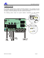
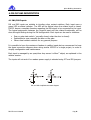
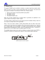
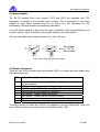
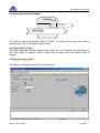
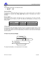
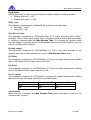
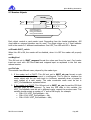
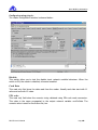
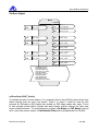
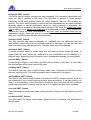
IOL332 Controller
User’s Manual
Apice Building Automation
The information included in this document is property of Apice s.r.l. and can be changed
without notice.
Apice s.r.l. will not be liable for errors that might be contained herein and for direct or
indirect accidental damage related to the supply, performance or use of material which
this document refers to.
It is forbidden to make soft and hard copies of this document, to translate or
manipulate all or part of it without the prior written consent of Apice s.r.l.
Vers.:
1.0
1.1
1.2
1.3
Date:
January 2003
August 2003
April 2006
December 2006
IOL332 User’s Manual
Note:
English version
Change connection for Wiegand reader
Integration for the PX10T reader
A note is added for the RJ45 connector reader
Pag. 2
Apice Building Automation
SUMMARY
SUMMARY ........................................................................................................................................3
1.INTRODUCTION...........................................................................................................................5
2.TECHNICAL SPECIFICATIONS ...............................................................................................6
3.INSTALLATION ............................................................................................................................7
4.IOL332 HW DESCRIPTION ........................................................................................................8
4.1 IN1/IN2 INPUTS ...........................................................................................................................8
4.2 TAMPER INPUT .............................................................................................................................9
4.3 RELAY OUTPUTS ........................................................................................................................10
4.4 READER CONNECTORS ...............................................................................................................10
4.5 ISO TTL Data+Clock Interface.............................................................................................12
4.6 Wiegand Interface ................................................................................................................12
4.7 Selecting ISO clock+data or Wiegand Interface...................................................................13
4.8 Card Readers Power Supply .................................................................................................13
4.9 IOL332 POWER SUPPLY ............................................................................................................14
4.10 NETWORK CONNECTION ..........................................................................................................14
4.11 SERVICE PIN AND ERVICE LED ................................................................................................14
5. IOL332 APPLICATON GUIDELINE .......................................................................................15
CONVENTIONS IN THE PRESENT USER MANUAL ................................................................................16
5.2 NODE OBJECT ............................................................................................................................17
nviRequest SNVT_obj_request ...................................................................................................17
nvoStatus SNVT_obj_status.........................................................................................................17
nvoFileDirectory SNVT_address ................................................................................................17
nvoAlarm SNVT_alarm ...............................................................................................................17
Important notice about nvoAlarm and nviRequest......................................................................18
SCPT_dev_maj_ver, SCPT_dev_min_ver ...................................................................................18
5.3 OPEN/CLOSE LOOP SENSOR(IN1 AND IN2) ...............................................................................19
nviValueFb SNVT_switch............................................................................................................19
nvoValue type SNVT_switch........................................................................................................19
Configuring inputs using plug-in ................................................................................................20
5.4 OPEN LOOP SENSOR(TAMPER)...................................................................................................23
nvoTValue SNVT_switch .............................................................................................................23
Configuring using plug-in ...........................................................................................................23
5.5 OPEN LOOP SENSOR(VOLTAGE) ................................................................................................24
5.6 CLOSE LOOP ACTUATOR(RELAY OUTPUTS) ..............................................................................25
nviValue.......................................................................................................................................25
nvoValueFb .................................................................................................................................25
Configuring using plug-in:..........................................................................................................25
5.7 READERS OBJECTS .....................................................................................................................27
nviDisable SNVT_switch .............................................................................................................27
nvoMagCard................................................................................................................................27
nvoPinCode .................................................................................................................................27
Configuring using plug-in:..........................................................................................................28
5.8 DOOR OBJECT ............................................................................................................................31
nviDoorState SNVT_Switch.........................................................................................................31
IOL332 User’s Manual
Pag. 3
Apice Building Automation
nviOpenE SNVT_Switch ..............................................................................................................32
nviOpenL SNVT_Switch ..............................................................................................................32
nviUnlock SNVT_Switch..............................................................................................................32
nviLock SNVT_Switch .................................................................................................................32
nvoBusy SNVT_Switch ................................................................................................................32
nvoFeedBack SNVT_Switch ........................................................................................................32
nvoLock SNVT_Switch ................................................................................................................32
nvoUnlock SNVT_Switch.............................................................................................................32
nvoOutDrive SNVT_Switch .........................................................................................................33
nvoIntruderAl SNVT_Switch .......................................................................................................33
nvoLeftOpenAl SNVT_Switch......................................................................................................33
nvoNoTransitAl SNVT_Switch ....................................................................................................33
Configuration using plug-in:.......................................................................................................33
5.9 SNVT_LEV_DISC TO SNVT_SWITCH CONVERTER OBJECTS..............................................35
nviLevDisc SNVT_levDisc...........................................................................................................35
nvoSwitch SNVT_switch ..............................................................................................................35
5.10 SNVT_SWITCH TO SNVT_LEV_DISC CONVERTER OBJECTS............................................36
nviSwitch SNVT_switch...............................................................................................................36
nvoLevDisc SNVT_lev_disc.........................................................................................................36
5.11 LOGIC FUNCTION OBJECT ........................................................................................................36
nviSLValues SNVT_switch ..........................................................................................................36
nvoSLValue SNVT_switch ...........................................................................................................36
Configuring using plug-in:..........................................................................................................37
5.12 USER LIST OBJECT ...................................................................................................................38
nviRestrict SNVT_switch .............................................................................................................38
Configuring using plug-in:..........................................................................................................38
6. ABOUT WINDOW ......................................................................................................................39
7. APPENDIX ...................................................................................................................................40
A. DOOR OBJECT ........................................................................................................................40
B. USE OF IOL332 WITHOUT EXTERNAL DATABASE MANAGER (LONSERVER) ........41
C. USE OF IOL332 WITH EXTERNAL DATABASE MANAGER (LONSERVER) .................42
D. SAMPLE 1: DOOR WITH ONE READER, WITHOUT DOOR STATE CONTROL..............43
E. SAMPLE 2: DOOR WITH ONE READER WITH DOOR STATE CONTROL .......................43
F. SAMPLE 3: USING TWO READERS .....................................................................................43
G. SAMPLE 4: USING PIN IDENTIFICATION.........................................................................44
H. SAMPLE 5: USING CARD + PIN IDENTIFICATION..........................................................44
IOL332 User’s Manual
Pag. 4
Apice Building Automation
1.INTRODUCTION
The IOL332 is a LONWORKS® based node, designed to control one or two protected gates in
the Globe2000 Access Control System.
Two HW versions are available:
• Standard version: 12VDC ±20% power supply
• Enhanced version: 12/24VAC – 15/36VDC power supply.
The Node IOL332 can manage two different card readers: magnetic or proximity, that can
be used to implement an access procedure based on user’s identification. Two different
application allow to manage from the reader ISO clock+data or wiegand data output
The Node IOL332 includes 3(three) On/Off Inputs:
• to sense the door status (open or closed)
• to acquire commands from a pushbutton to unlock the gate.
• one input is exclusive to tamper protection.
It includes also 3(three) relay outputs that can be used to drive:
• elecric locks
• automatic doors or gates
• local alarm device
Besides,it includes 4(four) outputs to drive LEDs and/or buzzers embedded in the card
readers, which are automatically driven by the node, to signal a granted or not granted
access and the door/gate status.
The node IOL332 communicates to the LONWORKS® network through the FTT10 transceiver
at 78,1 kbps.
The node IOL332 has got an on-board memory to store a local list up to 100 enabled card
codes. This list allow to build a simple access control without using any other devices like
database controller. The local list can be also used in case of failure of database manager
Some network variables allow to communicate the following events:
•
•
•
•
No transit after card recognition
Door left open
Unauthorized transit
Tamper alarm
IOL332 User’s Manual
Pag. 5
Apice Building Automation
2.TECHNICAL SPECIFICATIONS
Power supply
Power consumption
Inputs
Outputs
Card reader inputs
Card readers power
supply
Tamper
Transceiver
Processor
Clock frequency
Service Interface
Operating Temp.
Relative Humidity
Mechanical Structure
Mechanical Size
Application Program
Program ID
XIF & NXE files
NV Count
Alias Count
Plug-in
IOL332 User’s Manual
Standard: 12 VDC ±20%
Enhanced: 12-24 VAC or 15-36VDC
35 mA @ 12 V, 150 mA max.with Relays and LED
activated
2 General Purpose ON/OFF Inputs
1 Tamper Input
3 Relay Outputs, with NO contact protected with VDR 47
V
4 NPN OC Outputs whith optional limitation resistor
2 inputs at TTL level to interface ISO clock+data or
Wiegand data format
5VDC or 12VDC selectable, protected against short
circuit.
BOX opening, Readers wiring and external Input.
LONWORKS® FTT-10 78,1 Kb/s
Neuron Chip 3150
10 MHz
Service pin or manual entry – service led on board
0 – 50° C
20 – 80%
Plastic Box
Wall mounted or panel mount
140 x 125 x 30 mm
IOL3M01T (Clock+data)
IOL3M01W (Wiegand)
90:0A:0E:00:01:00:22:00
Iol3m01.xif
iol3m01T.nxe (Clock+data)
iol3m01W.nxe (Wiegand)
59
21
Available on LNS3 Platform
Pag. 6
Apice Building Automation
3.INSTALLATION
It is strongly recommended to install the IOL332 equipment in the protected and safe
location.The equipment could be hided over a floating ceiling or mounted inside a closed
box nearby, to prevent sabotage on the door’s electric lock contacts.
The following picture shows the typical standard connections to node IOL332.
IOL332 User’s Manual
Pag. 7
Apice Building Automation
4.IOL332 HW DESCRIPTION
4.1 IN1/IN2 Inputs
IN1 and IN2 inputs are suitable to interface clear contact switches. Each input owns a
green LED as status indicator. The LED will be lighted when the related input is closed.
IOL332 leaves a complete freedom regarding the HW signal to be connected to the input.
The logical assignment between the physical input and the related functionality will be
done throught binding during the SW configuration. Each input can be used to interface:
•
•
•
Door or gate state switch ( normally closed, when the door is closed).
Pushbutton,to open manually the door or the gate.
Others clear contact switches for any general purpose.
It is possible to have the maximum freedom in cabling inputs,but we recommend to keep
the same connection diagram when wiring similar IOL332 in a single project, in order to
simplify configuration and maintenance.
Each input is managed by an open/close loop sensor LONMARK® object, as explained in the
relative session.
The inputs will not work if no readers power supply is selected using JP7 and JP8 jumpers.
IN1 and IN2 simplified schematic diagram
IOL332 User’s Manual
Pag. 8
Apice Building Automation
4.2 Tamper Input
The special TAMPER input is suitable to interface a normally closed clear contact switch.
When this input is not used, it must be kept closed using a wire jumper. The short-circuit
wire jumper is included in the delivered IOL332 node. Tamper controls:
•
•
•
•
The
The
The
The
box cover closing, using the particular spring switch.
reader 1 wiring.
reader 2 wiring.
external tamper input.
When one of these conditions fail, a tamper alarm is generated, as explained in the
session related to the tamper LONMARK® object.
The spring switch to detect the box cover opening cannot be disabled. Always, when the
box is open, the tamper alarm will be generated.
Wires 7 and 8 are used to detect a reader disconnection from the node. These wires
usually must be kept short-circuit together. When the connection between wire 7 and 8 is
cut, a tamper alarm will be generated. The reader wiring protection can be disabled
jumpering the JP10 regarding the reader 1 and JP11 regarding the reader 2. Remember to
keep the JP10 or JP12 closed, when the related reader is not used.
The available tamper input can be used to interface an external switch when IOL332 is
mounted in a larger box containing other devices, to be protected against sabotage.
TAMPER simplified schematic diagram
IOL332 User’s Manual
Pag. 9
Apice Building Automation
4.3 Relay Outputs
The IOL332 includes three relay outputs. OUT1 and OUT2 are equipped with 47V,
suppressor in parallel to the normally open contacts. This is performed to use these
outputs to drive highly inductive load as an electric lock coil. Regarding the SW
functionality, the three outputs are completely equivalent.
A red LED status indicator is light when the relay is activated. The three pushbuttons, one
for each outputs, allow to test the node outputs cabling, just pressing them.
The max. allowable load in output contact is 1A, with 48V max.
Relay outputs simplified schematic diagram
4.4 Reader Connectors
There are two RJ45 connector each one includes 8 PIN, to interface two card readers with
the following pin-out:
PIN
#
1
2
3
4
5
6
7
8
Signal description
+VCC reader power supply. 5VDC or 12VDC selectable. Short
circuit protection
GND reader power supply and common signal reference
CLOCK signal for ISO interface or Wiegand 0
DATA signal for ISO interface or Wiegand 1
LD1 output – Usually green LED driving
LD2 output – Usually red LED or buzzer driving
Tamper
Tamper
To easily interface a reader with IOL332, we suggest to use the PL8M board, which has
got an RJ45 and screw connectors,each one of them include 8 PIN.
IOL332 User’s Manual
Pag. 10
Apice Building Automation
Card reader connection using the PL8M board
Card reader connection using direct wiring
Note: the IOL332 doesn’t manage the Card Present signal and doesn’t drive the buzzer
could come from the reader; in this case these two wire haven’t to be connected.
The picture shows the correct connection between the node and the readers. A junction
box which includes PL8M could be installed near the card reader. Junction box is
connected to IOL332 thought a 8 wire patch cord using two RJ45 connector. The card
reader is connected to the PL8M screw terminal, in order to simplify cabling and further
maintenance operations.
Reader connectors simplified schematic diagram
IOL332 User’s Manual
Pag. 11
Apice Building Automation
Be careful to insert the 680 ohms limitation resistor when driving LED directly with LD1
and/or LD2 outputs. To insert the limitation resistor, the related jumper must be kept
open.
LD1 and LD2 output can be set, to drive 3(three) different HW configurations:
•
•
•
One LED
Two LEDs
One LED + One Buzzer
These outputs can be used to monitor the door state too. More details about configuration
will be given in the “Reader Object” chapter.
4.5 ISO TTL Data+Clock Interface
This interface is the more used with magnetic card reader. It consists of two signal lines,
the clock and the data. During the clock failing edge, the data is valid. To be managed by
IOL332, the clock signal must become active at least 3ms before starting valid data, as
represented in the diagram below. This is not a problem for standard magnetic card
reader, because magnetic card encoding is according to this requirement. Be careful,
when interfacing a device with ISO data+clock output emulation. The Card Present signal
(CP), required in the APICE IOL222 node, is not necessary in IOL332. No external diodes
or resistor are required.
Clock + Data ISO interface recommended timing
4.6 Wiegand Interface
This interface consists of two signal, the logic level 0 and the logic level 1. Usually both
lines are to logic level 1. When one line goes to level “0” and returns to level “1” the
related logic level is transmitted. Only one line at time can transmit one data pulse.In
order to interface a device with the IOL332, the distance between the data pulses must
be 4ms or greater, as shown in the following picture:
IOL332 User’s Manual
Pag. 12
Apice Building Automation
4
Wiegand interface recommended timing
4.7 Selecting ISO clock+data or Wiegand Interface
No HW operation is required to select, ISO clock+data or wiegand interface. The
difference is in application loaded into the node. One application manages two ISO
clock+data card reader, the other application manages wiegand interface. It is not
possible, to use one reader with ISO clock+data interface and the other with wiegand
interface. Please,refer to the application list. The node application can be changed
downloading it into the node throught FTT-10 LONWORKS® network.
4.8 Card Readers Power Supply
Card readers power supply can be 5Vdc or 12Vdc selectable. Both readers must work with
the same voltage, or 5Vdc or 12Vdc . The card readers power supply is protected against
short-circuit. After the short-circuit protection intervention, to reset it is necessary to
remove the cause and power off the node. The same power supply is used to power the
inputs IN1, IN2 and TAMPER, too. Power supply selection is performed using JP7 and JP8
jumpers. Jumpering JP7 and JP8 in wrong position will cause no damage to the IOL332
board, but the equipment could not properly work. Apice S.r.l. will be not responsible for
any damage caused by improper jumper setting.
Card reader power supply jumper selection
IOL332 User’s Manual
Pag. 13
Apice Building Automation
4.9 IOL332 Power Supply
Two different models are available:
• IOL332 with 12Vdc ±20%
• IOL332 with 15 to 36VDC or with 12 to 24VAC.
The extended power supply model has one additional DC/DC converter mounted directly
on PC board. The ± polarity must be respected in 12VDC power supply model. The
extended power supply model is polarity insensitive.
It is recommended to use a different power supply line from IOL332 line, to power electric
lock coils or other power devices. Don’t exceed 300mt power supply cable length and use
the appropriate cable section, to guarantee the minimum power supply to the node even if
in max. load conditions.
The 12VDC power supply model can be easily connected to a 12V battery back-up power
supply system.
4.10 Network Connection
We recommend to follow Echelon® guidelines to cable LONWORKS® network. IOL332 works
using FTT-10A, free topology 78,1Kb network interface. The Network is polarity
insensitive.
4.11 Service Pin and ervice LED
The IOL332 node is provided with service pin pushbutton and service LED. The
pushbutton is used, to send to an installation or diagnostic tool the unique node NeuronId. The service LED is useful to discovery the node state.
Service LED
Flash at power ON, then OFF
1s OFF at power ON, then ON
Blinking at 1s period
Always ON
Always OFF
Node state
Configured. The node is installed in one network
Applicationless. The node has not application
Unconfigured. The node must be installed in one network
Damaged
Damaged
The IOL332 node is delivered in the Unconfigured state. The application will not run until
the node will be installed in one network using the opportune SW tool. We recommend to
use Echelon® LNS3 based installation tool.
IOL332 User’s Manual
Pag. 14
Apice Building Automation
5. IOL332 APPLICATON GUIDELINE
5.1 LONMARK® Objects List
IOL332 contains 18 LONMARK® objects as listed below:
-
1 Node object
-
2 open/close loop sensor related to IN1 and IN2
o
o
o
-
Obj 3: DsOutput[0]
Obj 4: DsOutput[1]
Obj 5: DsOutput[2]
type 3:20006
type 3:20006
type 3:20006
physical output 1
physical output 2
physical output 3
Obj6:
Obj7:
Reader[0]
Reader[1]
type 3:20008
type 3:20008
physical reader input 1
physical reader input 2
Obj8:
DsTamper
type 3:20009
physical tamper protection
Obj9:
DsVoltage
type 3:20009
not used
Obj10: LevDisc2Switch[0]
Obj11: LevDisc2Switch[1]
type 3:20002
type 3:20002
no hardware dependences
no hardware dependences
2 SNVT_switch to SNVT_lev_disc converter
o
o
-
physical input 1
physical input 2
2 SNVT_lev_disc to SNVT_switch converter
o
o
-
type 3:20005
type 3:20005
1 open loop sensor not used in this release
o
-
Obj 1: DsInput[0]
Obj 2: DsInput[1]
1 open loop sensor related to TAMPER input
o
-
type 0
2 reader objects related to the card reader inputs
o
o
-
Node object
3 close loop actuator related to relay outputs.
o
o
o
-
Obj0:
Obj12: Switch2LevDisc[0]
Obj13: Switch2LevDisc[1]
type 3:20003
type 3:20003
no hardware dependences
no hardware dependences
Obj14: Door[0]
Obj15: Door[1]
type 3:20009
type 3:20009
no hardware dependences
no hardware dependences
Obj16: SLogics
type 3:20010
no hardware dependences
Obj17: UserList
type 3:20012
configurable reader dependence
2 door objects to handle the gate control
o
o
-
1 Logic functions object
-
1 User list object
o
o
The present data sheet describe each object kind listed above. Each functional object can
contains configuration property which are using direct access read/write according to
LONMARK® interoperability guideline V 3.1. In order to properly configure the node, it is
suggested to use LONWORKS® installation tool LNS3 based. APICE provides a plug-in, using
LNS3 server, to easily configure the node.
IOL332 User’s Manual
Pag. 15
Apice Building Automation
IMPORTANT
INFORMATION
We recommend to install in the equipment, APICE resource
files greater than or equal to version 1.9 before starting any
project using IOL332 node, in order to load the right
configuration types. APICE resource files are according with
LONMARK® specification. To load resource file under LNS use the
Echelon® LNS Resource File Catalog Utility.
Conventions in the present user manual
NV:
NVI:
NVO:
CP:
=
=
=
=
Network variable
Input network variable
Output network variable
Configuration property
SNVT_switch
This node application use SNVT_switch NV type to manage ON/OFF signal. When we
refer to ON and OFF value for this type of NV we assume that:
The NVI ignores the value field, only the state field is used and it is interpreted as:
• OFF when state field is 0
• ON when state field is greather than 0
The NVO drives both state and value fields in NV as:
• OFF value is sent out as value = 0,0 and state = 0
• ON value is sent out as value = 100,0 and state = 1
IOL332 User’s Manual
Pag. 16
Apice Building Automation
5.2 Node Object
Node object
Type 0
nv
nviRequest
SNVT_obj_request
nv
nvoAlarm
SNVT_alarm
nv
nvoFileDirectory
SNVT_address
nv
nvoStatus
SNVT_status
SCPT_devMajVer
SCPT_dev_min_ver
nviRequest SNVT_obj_request
This NV allow to manage all functional object included in the node as LONMARK®
specification required. Supported action for each objects are:
Objects
IN1 – IN2
TAMPER
VOLTAGE
OUT1..3
READERS
DOORS
CONVERTERS
LOGIC
USER LIST
Req
Mask
X
X
X
X
X
X
X
X
X
Normal Enable
X
X
X
X
X
X
X
X
X
X
X
X
X
X
X
X
X
X
Disable
X
X
X
X
X
X
X
X
X
Alarm
notify
enable
X
X
X
X
X
X
Alarm
notify
disable
X
X
X
X
X
X
Clear
alarm
X
X
X
X
X
X
nvoStatus SNVT_obj_status
This NV send out the requested object statut when a request is launched.
nvoFileDirectory SNVT_address
This NV is used to configuration properties direct read/write access.
nvoAlarm SNVT_alarm
This NV send out the object’s alarm state when it occurs. The object’s alarm state remains
active until a CLEAR_ALARM request is sent to the object. The nvoAlarm NV value reflect
the last alarm event in the node. When a CLEAR_ALARM is launched to an object, the
nvoAlarm NV is updated with the new alarm state. The ALRM_NO_CONDITION is sent out
only if the alarm cause is dropped, otherwise a new alarm condition is updated. More
details about alarm are described in the chapters related to each object.
IOL332 User’s Manual
Pag. 17
Apice Building Automation
Important notice about nvoAlarm and nviRequest
In the previous version the object’s alarm status sent out from nvoAlarm NV has not been
completely tested. Also the object managed by nviRequest will be completely tested in the
next release. Some plug-in windows have in the top the management of the object 0 as
show in the followed picture.
The working of this frame has not been documented in the present user manual because
it is related with the full implementation and testing of alarm and object request features.
Please note this frame is operative, un-checking the enable box means disable the object.
In case of accidental setting in this frame, the object will restore the default setting just
resetting the device.
SCPT_dev_maj_ver, SCPT_dev_min_ver
These configuration properties are read only an cannot be changed. They are useful to
know the application version.
Remarks: The SCPT_dev_min_ver contains important information regarding the ISO
clock+data or wiegand reader input IOL332 capability.
•
•
Even version numbers (0, 2, 4…) identifies ISO clock+data interface
Odd version numbers (1, 3, 5…) identifies Wiegand interface
In this manner the IOL332 will keep the same network interface and program ID in both
reader interface mode. We remember that two different applications are available for each
reader interface.
Available IOL332 files:
•
•
•
Iol3m01.xif
iol3m01T.nxe
iol3m01W.nxe
IOL332 User’s Manual
It is the same for both reader interfaces.
Application image ISO clock+data interface.
Application image wiegand interface.
Pag. 18
Apice Building Automation
5.3 Open/Close Loop Sensor(IN1 and IN2)
DSInput
3:20005
nv
nviValueFb
SNVT_switch
nv
nvoValue
SNVT_switch
SCPTclOffDelay
SCPTclOnDelay
SCPTMaxSendTime
UCPT_alarmNotify
UCPT_DisplaySwitchInputMode
Both physical input 1 and Input 2 are managed by an open/close loop sensor object. The
selection between open and close loop functionality is automatically performed depending
from nviValueFb binding:
•
•
When nviValueFb is not bound, the object work as an open loop sensor.
When nviValueFb is bound, the object work as a close loop sensor.
nviValueFb SNVT_switch
This NV is the feedback input value used in close loop sensor functionality only. It is
complied with LONMARK® directive.
nvoValue type SNVT_switch
This is the main NV in the object. Object’s configuration properties affects the NV value
behavior as explained below.
Input 1 and input 2 are not default related with any door functionality. The nvoValue NV
must be bound to the controller or actuator object to obtain the desiderated effect.
These inputs could be used to control the door state, to open the door, etc…
IOL332 User’s Manual
Pag. 19
Apice Building Automation
Configuring inputs using plug-in
The input configuration window in APICE IOL332 plug-in is showed below:
FeedBack (Close loop only)
This is the nviValueFb value monitored on the network. Even if this is an input network
variable, the plug-in doesn’t allow to change its value. It is showed for monitor purpose
only.
• Dark LED = OFF
• Green LED = ON
Output Value:
This is the nvoValue monitored on the network. This is a read only value because the
network variable has output direction.
• Dark LED = OFF
• Green LED = ON
Max Send Time
This parameter affect the SCPT_maxSendTime configuration property. The Max Send
Time value is ignored when the object works like close loop mode because it could cause
problems when multiple sensor objects are bounded to a single actuator. When Max
IOL332 User’s Manual
Pag. 20
Apice Building Automation
Send Time is set with a value greather than 0, the nvoValue is propagated on network at
least each Max Send Time seconds.
Input Mode
This parameters affect the UCPT_DisplaySwitchInputMode configutation properties.
It can assume 5 different values. Depending the object is working in open loop or in close
loop mode, the Input mode can assume different means.
Value
Icon
open loop mode
Description
Default
Opened input = OFF value
Closed input = ON value
Inverted in open loop
Opened input = ON value
Closed input = OFF value
Opening only
Only the OFF value is propagated when the
input is opening.
Closing only
Only the ON value is propagated when the input
is closing.
Both
Same as Default
Value
Icon
close loop mode
Description
nvoValue will change (reversing the nviValueFb
Default
value) when the input will change from opened
to closed status.
Inverted in open loop
Same as Default
nvoValue will change (reversing the nviValueFb
Opening only
value) when the input will change from closed
to opened status.
Closing only
Same as Default
IOL332 User’s Manual
Pag. 21
Apice Building Automation
Both
nvoValue will change (reversing the nviValueFb
value) when the input will change anyway.
ON Delay
This parameter affect the SCPTclOnDelay configuration parameter.
In open loop working mode:
This is the delay between the moment where one input change event generate an ON
value (see Input Mode) and when the ON value is propagated to the output network
variable. The physical input must remains in this state during all On Delay time otherwise
the operation will be interrupted and the value will be not propagated.
In close loop working mode:
This is the delay between the moment where one allowable input change event is
detected (see Input Mode) and when the ON value must be propagated to the output
network variable (because the feedback input value is OFF). The physical input must
remains in this state during all On Delay time to accept the current input change event.
OFF Delay
This parameter affect the SCPTclOffDelay configuration parameter.
In open loop working mode:
This is the delay between the moment where one input change event generate an OFF
value (see Input Mode) and when the OFF value is propagated to the output network
variable. The physical input must remains in this state during all Off Delay time otherwise
the operation will be interrupted and the value will be not propagated.
In close loop working mode:
This is the delay between the moment where one allowable input change event is
detected (see Input Mode) and when the OFF value must be propagated to the output
network variable (because the feedback input value is ON). The physical input must
remains in this state during all Off Delay time to accept the current input change event.
IOL332 User’s Manual
Pag. 22
Apice Building Automation
5.4 Open Loop Sensor(Tamper)
DsTamper
3:20009
nv
nvoTValue
SNVT_switch
SCPT_invrtOut
SCPTmaxSendTime
UCPT_alarmNotify
This object controls the tamper circuit in IOL332. It works like an open loop sensor,
sending out in NV nvoTValue the tamper state.
nvoTValue SNVT_switch
This NVO reflect the hardware tamper state. When it is not reversed, the NV assume an
OFF value when the tamper circuit is closed and ON value when the tamper circuit is
opened.
Configuring using plug-in
The tamper configuration window is showed below:
IOL332 User’s Manual
Pag. 23
Apice Building Automation
Value
This indicator monitor the nvoTValue NV value.
• Dark LED = OFF
• Red LED = ON
Max Send Time
Correspond to SCPTmaxSendTime CP. When it has a value greater than 0, the NVO is
propagated at maximum each Max Send Time seconds in according with LONMARK®
directives.
Invert output
Correspond to SCPT_invrtOut CP. When the box is unchecked the CP value is ST_OFF,
when checked the CP value is ST_ON. This affect the NVO behavior as showed in the
followed table:
SCPT_invrtOut
ST_OFF (unchecked)
ST_ON (checked)
Tamper closed
OFF
ON
Tamper opened (alarm)
ON
OF
Alarm notify
Correspond to UCPT_alarmNotify CP. When the box is checked, the tamper alarm is sent
out thought the object 0 nvoAlarm. When the box is unchecked, the alarm is not sent out.
The alarm state ignore the invert output setting. The alarm is sent out when the tamper
circuit is opened.
5.5 Open Loop Sensor(Voltage)
DsVoltage
3:20009
nv
nvoVValue
SNVT_switch
SCPT_invrtOut
SCPTmaxSendTime
UCPT_alarmNotify
The object functionality is not implemented in this release.
IOL332 User’s Manual
Pag. 24
Apice Building Automation
5.6 Close Loop Actuator(Relay Outputs)
DsOutput
3:20006
nv
nviValue
SNVT_switch
nv
nvoValueFb
SNVT_switch
SCPTclOffDelay
SCPTclOnDelay
SCPTdefOutput
SCPTinvrtOut
SCPTmaxRcvTime
UCPT alarmNotify
Each relay output is driven by one close loop actuator object, which can work as open
loop actuator too. In this case the nvoValueFb will be not used.
nviValue
This network variable drives the relay state in according with Invert Output setting.
nvoValueFb
This NV reflect the real relay state. When the relay is ON, the NV is ON, when the relay is
OFF the NV is OFF. Reverse mode doesn’t affect this NV.
Configuring using plug-in:
The output setting window is showed below:
IOL332 User’s Manual
Pag. 25
Apice Building Automation
Input value
Clicking this switch to drive the input network variable nviValue for testing purpose.
• Position with red 0 = OFF
• Position with green 1 = ON
Relay state
This indicator, monitoring the nvoValueFb NV, shows the real relay state:
• Dark LED = OFF
• Green LED = ON
Max Receive time
This parameter correspond to SCPTmaxRcvTime CP. It works according with LONMARK®
directives. When it has a value greater than 0, the object controls that at least one update
in nviValue is received within the Max Receive Time. If no update are received within
this time interval, the output will turn to the default value and one alarm could be sent out
from the nvoAlarm NV in object 0.
Default output
This parameter correspond to SCPTdefOutput CP. This is the value assumed to the
physical relay after a reset operation or in case of Max Receive Time failure.
Off Delay
This parameter correspond to SCPTclOffDelay CP. This is the delay between the nviValue
goes to OFF value and the output relay turn to OFF.
On Delay
This parameter correspond to SCPTclOnDelay CP. This is the delay between the nviValue
goes to ON value and the output relay turn to ON.
Invert output
This parameter correspond to SCPTinvrtOut. It reverse the relation between the nviValue
value and the real relay state, as showed in the table below:
nviValue
OFF
ON
Invert Out = OFF
OFF
ON
Invert Out = ON
ON
OFF
Alarm notify
When this box is checked, the Max Receive Time failure will send an alarm to the
nvoAlarm NV in object 0.
IOL332 User’s Manual
Pag. 26
Apice Building Automation
5.7 Readers Objects
Reader
3:20008
nv
nviDisable
SNVT_switch
nv
nv
nvoMagCard
SNVT_magcard
nvoPinCode
SNVT_str_asc
SCPTmaxSendTime
UCPT_AlarmNotify
UCPT_pinCodeMask
UCPT_ReaderLedMode
Each object controls a card reader input. Depending from the loaded application, ISO
clock+data or wiegand interface can be used. The object drives up to 2 local indicator
built in the reader in 3 different combinations: One LED, Two LED and LED + Buzzer.
nviDisable SNVT_switch
When this NV is ON, the reader will be disabled, when it is OFF the reader will properly
work.
nvoMagCard
This NV sent out in SNVT_magcard format the value read from the card. Card reader
input can work with ISO clock+data and wiegand input as explained in the first user
manual session.
nvoPinCode
This variable has different mean, depend by the reader type.
1. If the reader isn’t a PX10T: This NV sent out in SNVT_str_asc format a code
conversion from card data present in nvoMagcard. This is used to interface the
reader object with the pin code input in LonServer, especially when a keypad is
used instead of a card reader. The code conversion mask must be set in
UCPT_PinCodeMask as explained below.
2. If the reader is a PX10T: This NV sent out in SNVT_str_asc format the PIN that
the user digit by the keyboard. To have the PIN code in this variable, the
UCPT_PinCodeMask must be set in different mode, respect the previous case. This
variable should contain a number of “t” as the PIN lenght, for example:
• PIN=123: UCPT_PinCodeMask = ttt;
• PIN=1234: UCPT_PinCodeMask = tttt;
• PIN=12345: UCPT_PinCodeMask = ttttt;
IOL332 User’s Manual
Pag. 27
Apice Building Automation
Configuring using plug-in:
The reader configuration window is showed below:
Disable:
This switch allow you to test the disable input network variable behaviour. When the
switch is ON, the reader is disabled, otherwise enabled.
Card Data
This read only field show the data read from the reader. Usually card data start with 11
value and end with 15 value.
PIN code:
This read only field show the numeric string obtained using PIN code mask conversion.
This value is the same propagated to the output network variable nvoPinCode. The
numeric value is used for local users list, too.
IOL332 User’s Manual
Pag. 28
Apice Building Automation
Max Send Time
Configuring this property with a value greater than 0, means the nvoMagCard will updated
at least each Max Send Time sec. When an update will occur caused by Max Send
Time, the nvoMagCard will contain all data field with value 0 to avoid conflict with an
update caused by card read.
BE CAREFULL the LonServer or the access manager controller handles the Max Send
Time from the reader, otherwise set it to 0 value.
PIN Code Mask:
This property must be configured in one of the followed cases:
•
To treat card data as PIN code, especially when one keypad, with ISO clock+data
or wiegand interface, is connected to a reader input.
•
To use the internal users list.
The purpose of PIN Code Mask is to extract a numeric card code from the card data
string. The mask work with the followed specify:
•
•
•
•
A character between numeric 0..9 must match the card code but will be not
extracted.
The lower case character p is used in the position were we want to extract the card
code.
The lower case character x is used to indicate any character in card data, but it will
be not extracted.
Starting and ending character 11 and 15 are automatically skipped
Example:
Card data
Pin Code Mask
PIN code
11
1
1
2
2
2
2
1
1
2
p
2
1
p
1
5
p
5
6
p
6
15
Att! : This configuration is wrong if the reader is a PX10T, see above in
nvoPinCode variable description.
IOL332 User’s Manual
Pag. 29
Apice Building Automation
Reader LED mode
The reader could have the followed local monitor devices:
•
•
•
One green LED
One green LED and one red LED or one two colors LED.
One green LED and one Buzzer
We can select this configuration from the combo Box setting one of the related values:
•
•
•
One Led
Two LED
Led + Buzzer
Then automatically the bad read and access not allowed events will be monitored.
The reader local monitor devices can also show the door status. Depending from binding
and configuration, each reader could be used in conjunction with door 1 or door 2. For this
reason we can select other monitor information coming from each door. Checking and unchecking the related box we can add or remove the door monitor condition:
•
•
•
•
•
Open CMD:
Unlocked:
No transit:
Left open:
Intruder:
When
When
When
When
When
the door receives an open command
the door is in unlock condition
the door generates a No Transit Alarm.
the door generates a Left Open Alarm.
the door generates an Intruder Alarm.
Please note the default value is all unchecked.
Hardware connection:
Green LED to LED1 output.
Red LED or buzzer to LED2 output.
Remark: an internal limitation resistor can be inserted in the output circuit in order to
drive LED directly. See hardware session for more details.
IOL332 User’s Manual
Pag. 30
Apice Building Automation
5.8 Door Object
Door
nv
nviDoorState
SNVT_switch
3:20009
nv
nvoBusy
SNVT_magcard
nv
nvoFeedBack
SNVT_lev_disc
nv
nviOpenE
SNVT_switch
nv
nvoLock
SNVT_switch
nv
nviOpenL
SNVT_switch
nv
nvoUnlock
SNVT_switch
nv
nvoOutDrive
SNVT_switch
nv
nviUnlock
SNVT_switch
nv
nvoIntruderAl
SNVT_switch
nv
nviLock
SNVT_switch
nv
nvoLeftOpenAl
SNVT_switch
nv
nvoNoTransitAl
SNVT_switch
SCPTmaxSendTime
SCPTmaxRcvTime
UCPT_AlarmNotify
UCPT_Elock_pulseT
UCPT_DoorMode
UCPT_door_OpenT
UCPT_maxOpenT
UCPT_maxAlarmT
UCPT_minAlarmT
UCPT_noTransitAlmT
nviDoorState SNVT_Switch
To activate the door control feature, it is necessary bind to this NVI the value of the door
status coming from an open loop sensor. Input 1 or Input 2 could be used for this
purpose. An ON value in NVI means door closed, an OFF value means door open. This is
to use normally closed switch (closed with door closed) without change the open loop
sensor default behavior. To avoid debounce problem, On Delay and Off Delay could be
set in open loop sensor object. A Max Receive Time can be programmed for this NVI.
IOL332 User’s Manual
Pag. 31
Apice Building Automation
nviOpenE SNVT_Switch
This NVI is used to receive a single open door command. The command is performed only
when the NVI is updated to ON value. The NVI level is ignored, it could remains
indefinitely to ON value without affect the object behavior. Also the OFF updates are
ignored. This NVI is used normally to receive the open command from an access manager
controller and/or a manual pushbutton. When an open command is processed, the
nvoOutDrive NV is updated to ON value and it will return OFF when the electric lock pulse
time is expired. If the electric lock pulse time is programmed to value 0, the nvoOutDrive
remains ON during the time programmed in the door must be opened within xxx sec
parameter in plug-in, but in this case it is necessary to have the door state control. In this
case, the nvoOutDrive stay ON whit the opened door.
nviOpenL SNVT_Switch
This NVI performs the same functionality of nviOpenE with the difference that the
nvoOutDrive remains ON until the nviOpenL remains to ON value, but not less than the
minimum electric lock programmed time. The door alarm will be not disabled.
nviUnlock SNVT_Switch
To switch the door object in unlock state, this NVI must be driven to the ON value. In
unlock state the door alarms are inhibited and the nvoOutDrive can be affected in 3
different ways, depending from the setting (see in configuration session for more details).
nviLock SNVT_Switch
To put the door object in Lock state, this NVI must be driven to ON value. In Lock state
the nvoOutDrive will be never drive to ON value.
nvoBusy SNVT_Switch
This NVO is used only when is used the door state input. It assume the ON value during
the door opening cycle. The nvoBusy behavior can be observed in the plug-in.
nvoFeedBack SNVT_Switch
This NVO is only used to send the door information to APICE LonServer device, when we
are interesting to log in event memory the door state and alarms. If the door state is not
used, it is not necessary to bind this NVO to LonServer and in this case set the LonServer
gateEvLog configuration property must be set to 0, to disable the gate event recording.
nvoLock SNVT_Switch
This NVO reflect the object lock status. When the door is locked, this NVO assume the ON
value.
nvoUnlock SNVT_Switch
This NVO reflect the object unlock status. When the door is unlocked, this NVO assume
the ON value.
IOL332 User’s Manual
Pag. 32
Apice Building Automation
nvoOutDrive SNVT_Switch
This is the NVO which drive the electric lock output. It must be bound to an open or close
loop actuator. One of the three relay outputs could be used for this purpose. A Max Send
Time can be programmed for this NVO.
nvoIntruderAl SNVT_Switch
This NVO goes to ON value when the door is open without a preventive open command.
The NVO stay to ON value at least the minimum intruder and left open alarm time and
return to OFF when the door is closed or the maximum intruder and left open alarm time
is expired. Programming the max time to 0 means the NVO will turn OFF only when the
door will be closed.
nvoLeftOpenAl SNVT_Switch
This NVO goes to ON value when the doors remains open more than the time
programmed in the door cannot stay opened more than xxx sec. The NVO stay to ON
value at least the minimum intruder and left open alarm time and return to OFF when the
door is closed or the maximum intruder and left open alarm time is expired. Programming
this time to 0 means the NVO will turn OFF only when the door will be closed.
nvoNoTransitAl SNVT_Switch
This NVO goes to ON value when, after a door open command, the door is not open
within the time programmed in the door must be opened within xxx sec parameter. This
NVO will stay to ON value the time programmed in Not transit alarm time parameter.
Configuration using plug-in:
IOL332 User’s Manual
Pag. 33
Apice Building Automation
Open and keep opened:
This switch drive the nviOpenL NV.
Open Once:
This switch send an ON update to nviOpenE NV. The switch will return automatically to
OFF position
Unlock:
This switch drive the nviUnlock NV. The indicator in the right show the nvoUnlock value.
Lock:
This switch drive the nviLock NV. The indicator in the right show the nvoLock value.
Out Drive:
This indicator show the nvoOutDrive NV value. This is the NV suitable to drive the electric
lock. When an input door state is bound to the object, the busy indicator will show the
nvoBusy NV value. It is possible to program a Max Send Time to nvoOutDrive NV.
Remember to execute a node reset after programming the Max Receive Time.
Door state:
This icon showing an opened and a closed door show the door state. If the nviDoorState
NV is not bounded, this indication could be ignored. A Max Receive Time can be set to
nviDoorState NV. When the Max Receive Time fails, an alarm will be generated to the
nvoAlarm NV in object 0.
Elock pulse time (0 = not impulsive elock):
This is the electric lock pulse time. Only integer values are allowed. It is possible to
program 0 in this field, but in this case the door state must be used. This is to use electric
lock which need to be driven when the door is open too. In this case, after receiving an
open command, the nvoOutDrive will stay ON during the time programmed in Door must
be opened within xxx sec parameter, when the door is not opened.
OutDrive action when unlock the door:
This parameter define the electric lock behavior when the door goes in the Unlock state.
One of these tree different mode can be set:
• No effect:
• Give one pulse:
• Keep on:
IOL332 User’s Manual
The electric lock will be not affected
When goes in Unlock state, a single open command will be sent
to the electric lock.
The electric lock will stay on during as long the door unlock
state.
Pag. 34
Apice Building Automation
Door must be opened within xxx sec
If the door is not opened within this time, a No transit alarm will generate. If the electric
lock pulse time is set to 0, this is the duration of the electric lock pulse when the door is
not opened.
Min Intruder and Left Open alarm:
This is the intruder and left open alarm minimum time duration.
Max Intruder and Left Open alarm:
Intruder and left open Alarm stay active until the door remains open and not less than
minimum time. If the door will be not closed, it is possible to program a maximum alarm
time in this parameter. If this parameter is set with 0 value, the intruder and/or left open
alarm will be reset only when the door will be closed.
No transit alarm time:
This is the no transit alarm time duration.
Alarm notify:
This is to program which alarm will be sent in the nvoAlarm NV in object 0.
5.9 SNVT_lev_disc to SNVT_switch CONVERTER OBJECTS
LevDisc2Switch
3:20002
nv
nviLevDisc
SNVT_lev_disc
nv
nvoSwitch
SNVT_switch
IOL332 includes two objects to easily convert a SNVT_lev_disc NV to a SNVT_switch
NV.
nviLevDisc SNVT_levDisc
This is the input to receive a SNVT_lev_disc NV. The value ST_OFF will be interpreted
as OFF value, all the others values as ON value.
nvoSwitch SNVT_switch
This is the SNVT_switch output variable converted as explain in the SNVT_switch
convention in this manual (pag. 16).
This object has not configuration property to be programmed using plug-in.
IOL332 User’s Manual
Pag. 35
Apice Building Automation
5.10 SNVT_switch to SNVT_lev_disc CONVERTER OBJECTS
Switch2LevDisc
3:20003
nv
nviSwitch
SNVT_switch
nv
nvoLevDisc
SNVT_lev_disc
IOL332 contains two objects convert a SNVT_switch NV to a SNVT_lev_disc NV.
nviSwitch SNVT_switch
This is the input to receive a SNVT_switch NV. Values ON and OFF are interpreted as
explained in SNVT_switch convention in this manual (pag. 16).
nvoLevDisc SNVT_lev_disc
This is the SNVT_lev_disc output variable. An input OFF value will be converted in
ST_OFF output value, an ON input value in ST_ON output value.
This object has not configuration property to be programmed using plug-in.
5.11 Logic Function Object
SLogics
3:20010
nv
nviSLValues
SNVT_switch
nv
nvoSLValue
SNVT_switch
UCPT SwitchLogics
This object allow to perform logical operation up to 63 SNVT_switch output network
variables. The output network variables must be bound to nviSLValues and the
nvoSLValue will output the logical operation requested between all bounded output
network variables.
nviSLValues SNVT_switch
Accept multiple output network variables to perform a logical operation.
nvoSLValue SNVT_switch
Result of the logical operation. Each time the object receive a network variable update, it
will perform (if it is necessary) a poll operation in nviSLValues to determine the result.
IOL332 User’s Manual
Pag. 36
Apice Building Automation
Configuring using plug-in:
Logic operator:
And:
Not and:
Or:
Not Or:
Xor:
Not xor:
All
All
All
All
All
All
NV must have ON value to obtain output ON value, otherwise OFF.
NV must have ON value to obtain output OFF value, otherwise ON.
NV must have OFF value to obtain output OFF value, otherwise ON.
NV must have OFF value to obtain output ON value, otherwise OFF.
NV must have similar value to obtain OFF value, otherwise ON.
NV must have similar value to obtain ON value, otherwise OFF.
Remark: Don’t use the XOR or NOT XOR functionality when an even number of output
network variables are bounded to nviSLValues.
Out value:
This indicator show the output value result.
IOL332 User’s Manual
Pag. 37
Apice Building Automation
5.12 User List Object
UserList
3:20012
nv
nviRestrict
SNVT_switch
UCPT UseRecordsIOL
This object contains the local users list. The local users list can manage up to 100 card
codes with 4 special flags as explained in configuration detail. Users list is used when:
•
•
The Enable user list box is checked in the reader object configuration.
The reader object cannot receive acknowledge from LonServer
To use the local users list, the card code must be converted to a numeric string, using the
pin code mask, as explained in the reader configuration setting.
nviRestrict SNVT_switch
When this NVI is set to ON value, the restrict access mode is enabled and only the users
with the restrict flag marked could gain the access.
Configuring using plug-in:
IOL332 User’s Manual
Pag. 38
Apice Building Automation
Restrict users access:
This switch allow to simulate ON and OFF value to nviRestrict NV.
Users list:
This is the 100 position users code list. In the first cell the card code must be
programmed. The card code is obtained from the reader using the PinCodeMask
conversion, when the card code doesn’t match any code in the users list, the card code
will be not valid. There are other 4 flags to complete the code enabling:
E1 = when checked the user can access from the reader 1
E2 = when checked the user can access from the reader 2
R1 = when checked the user can access from the reader 1 in restrict mode too (E1 also
checked)
R2 = when checked the user can access from the reader 2 in restrict mode too (E2 also
checked)
Both E1 and E2 unchecked means the code is disabled because the access is not allowed
in any readers.
6. ABOUT WINDOW
This is the about window in the plug-in
This is the about window, useful to discovery the application release running in the
IOL332. Application can be easily updated thought the LONWORKS® Network.
IOL332 User’s Manual
Pag. 39
Apice Building Automation
7. APPENDIX
A. DOOR OBJECT
The door object need at least the binding between the nvoOutDrive NV and one actuator,
to be able to give a physical output in order to power up the electric lock or the gate
automatism.
The door object send always ON value to give the open command to the output object.
Programming the output object CP is possible to reverse the operating mode between the
security fail (the default) to safe fail. In security fail the output relay is normally OFF. In
case of power failure the door will remain close. In safe fail the output relay will be
normally ON to keep the door close and when there is a power supply failure the relay will
turn OFF opening the gate. To work in safe fail mode, in the output object must be
programmed the Invert Out parameter to ON. When the output object is contained in
another physical node than door object, we advise to program the Max Send Time
parameter in door object and Max Receive Time in output object, configuring the
default output to the desiderate value, too.
In the binding showed above, the door object doesn’t control any door state and it will not
generate any alarm. Installing a door switch (usually a magnetic switch) to sense the door
status, we can use the door object full feature. The door switch will be connected to a
physical input, then bind to nviDoorState as the followed picture shows:
The door object will automatically detect the binding. In this case the full door object
feature can be used as the door alarms. The door object accept in nviDoorState OFF value
as door opened and ON value as door closed. This is to use the input object in the default
configuration. In fact usually the magnetic switch is closed whit the door closed. We
advise to program a minimal On delay and Off delay time in the input object to avoid fake
alarm in case of switch debouncing. A Max Receive Time related to nviDoorState can be
IOL332 User’s Manual
Pag. 40
Apice Building Automation
programmed. In case of failure an alarm will be send thought the nvoAlarm NV in object
0.
B. USE OF IOL332 WITHOUT EXTERNAL DATABASE MANAGER (LONSERVER)
After binding and configuring the door objects as explained in the previous page, the
IOL332 don’t need other binding to work using only the local users list. It is enough to
program the readers object CP and the users list, just using the plug-in. Each physical
reader can be programmed to open one door, checking the related box in the plug-in
reader window.
When one reader has been set to open one door, as in the example door 1, it is necessary
to create one opportune PIN code mask in order to extract a numeric code from the card
code, as explained in the present user manual at pag. 29. Each time one card run in the
reader, a card code will be read and consequently a numeric code will extract. To have the
authorized access, the code will match one in the users list and the opportune access right
specified with the flags E1, E2, R1, R4 will be comply as explain in the chapter
IOL332 User’s Manual
Pag. 41
Apice Building Automation
5. (pag. 38).
If the card has the right to access, an opening cycle is performed by the door object and
through nvoOutDrive NV the electric lock will be driven.
The door object will be used with or without the door state control, indifferently, like
explained in the previous page.
C. USE OF IOL332 WITH EXTERNAL DATABASE MANAGER (LONSERVER)
IOL332 can be easily interfaced with an external database manager controller working on
the LONWORKS® network. APICE LonServer product is suitable to control up to 8 door, where
two card readers + two keyboards can be managed for each door to gain the access right.
In the followed examples we assume to use the current LonServer version using
SNVT_lev_disc NV to handle ON/OFF value but the IOL332 is using for the same
purpose the SNVT_switch NV type. This type conflict because LONMARK® association has
declared obsolete the type SNVT_lev_disc and the APICE new product don’t use this NV
type. In the next future a new LonServer version using SNVT-switch NV type instead of
SNVT_lev_disc will be available. Tanks to the converter objects contains in IOL332 will
be always possible to use the product with old LonServer version, too.
IOL332 User’s Manual
Pag. 42
Apice Building Automation
D. SAMPLE 1: DOOR WITH ONE READER, WITHOUT DOOR STATE CONTROL
The reader object in IOL332, send data to the nvi01reader1 NV in LonServer Access
manager 1 object. If the code is valid the nvo01GateDrive NV will send the opening
command to the nviOpenE NV in door 1 object in IOL332, using in this case a
LevDisc2Switch converter. Finally the nvoOutDrive will send the opening command to the
relay output OUT 1. Remember to disable in LonServer the gate event recording in this
case.
E. SAMPLE 2: DOOR WITH ONE READER WITH DOOR STATE CONTROL
The door state input is bound to door 1 object. The LonServer can store the gate event
using the binding nvoFeedBack with nvi01gateFdbk. The rest is working like the previous
example.
F. SAMPLE 3: USING TWO READERS
In this example we are omitting the
door object driving because it
works always as explained in the
two previous examples. One reader
can be installed in each door side
and in this case it is enough to bind
the two readers object in IOL332 to
the same access manager. To
avoid conflict with LED indicator in
the reader when the card is not valid, bound always the reader 1 with the nviXXreader1
and reader 2 with nviXXreader2. Use also the convention to assign to the reader 1 the
IOL332 User’s Manual
Pag. 43
Apice Building Automation
entrance side and the reader 2 in exit side refer to the security area. For example the
outdoor reader will be the reader 1.
G. SAMPLE 4: USING PIN IDENTIFICATION
IOL332 is suitable to interface digital keypad instead of card reader. This kind of device,
which APICE propose in its catalogue too, send out in ISO clock+data or in wiegand
format the code type in the keyboard. In this case a typed code could be interpreted like a
‘card code’ without require any special feature in the reader controller (the IOL222 product
is suitable to do this too). The new feature introduced in IOL332 allow to treat the typed
code like a real PIN code and not like a card code. To do this, it is necessary to compose
one opportune PIN mask in the reader object configuration (see pag. 29) and bind the
nvoPinCode NV to nviXXKeyboard like in the followed picture.
The difference is the PIN code is treat as identification level 1 instead of 2 (card code) and
the PIN code programmed in AxWin access control software will be comply wit the typed
code in the keyboard.
H. SAMPLE 5: USING CARD + PIN IDENTIFICATION
To obtain CARD + PIN identification, it is possible to use the APICE JLON identification
terminal or use one keyboard as described above in conjunction with one reader. In this
case, we need to use both reader inputs in IOL332. As show in the picture we could
connect the reader to the reader 1 input and bind the nvoMagcard to nviXXreader1 in
access manager and the keyboard to the reader 2 input, programming PIN Mask and
binding the nvoPinCode to nviXXKeyboard1.
IOL332 User’s Manual
Pag. 44
Apice Building Automation
The Equipment is complied with European Specification
cє
IOL332 User’s Manual
Pag. 45
Apice Building Automation
APICE S.r.l.
Via G.B. Vico, 45/b - 50053 Empoli (FI) Italy
www.apice.org – [email protected]
BUILDING AUTOMATION – CONTROLLO ACCESSI
RILEVAZIONE PRESENZE - SISTEMI LONWORKSTM
IOL332 User’s Manual
Pag. 46