1
ED 40 - 437
Packaged Air Conditioners
Duct Connection Type [50Hz]
(Middle Static Pressure Application)
FDMG-AV1(S) Series
— Cooling Only —
ED40-437
Duct Connection Type
Middle Static Pressure
Application [50Hz]
FDMG-AV1(S) Series
1. External Appearance...............................................................................2
2. Power Supply and Nomenclature............................................................3
2.1 Power Supply ...........................................................................................3
2.2 Nomenclature ...........................................................................................3
3. Functions.................................................................................................4
3.1 FDMG-AV1(S) Series...............................................................................4
4. Specification............................................................................................5
4.1 50Hz .........................................................................................................5
4.2 50Hz (For Thailand) .................................................................................7
5. Optional Accessories ..............................................................................9
5.1 Optional Accessories................................................................................9
6. Dimensions ...........................................................................................14
6.1 Indoor Unit..............................................................................................14
6.2 Outdoor Unit ...........................................................................................16
6.3 Installation Service Space ......................................................................18
7. Piping Diagrams....................................................................................20
7.1 Indoor Unit + Outdoor Unit .....................................................................20
8. Wiring Diagrams....................................................................................21
8.1
8.2
8.3
8.4
8.5
Indoor Unit..............................................................................................21
Indoor Unit (For Thailand) ......................................................................21
Outdoor Unit ...........................................................................................22
Outdoor Unit (For Thailand) ...................................................................24
Field Wiring ............................................................................................27
9. Capacity Table ......................................................................................28
9.1 50Hz .......................................................................................................28
9.2 50Hz (For Thailand) ...............................................................................30
9.3 Capacity Correction Factor by the Length of Refrigerant Piping ............33
10.Fan Performance ..................................................................................34
11.Operation Limit......................................................................................37
11.1 50Hz .......................................................................................................37
11.2 50Hz (For Thailand) ...............................................................................37
12.Sound Level ..........................................................................................38
12.1 Overall Sound Level ...............................................................................38
12.2 Octave Band Level .................................................................................39
13.Electric Characteristics..........................................................................41
14.Field Piping ...........................................................................................42
14.1 Field Piping.............................................................................................42
15.Installation .............................................................................................45
15.1 FDMG-AV1(S) Series.............................................................................45
FDMG-AV1(S) Series
1
External Appearance
ED40-437
1. External Appearance
Indoor Unit
FDMG71AV1(S)
FDMG100AV1(S)
FDMG125AV1(S)
FDMG140AV1(S)
FDMG180AV1(S)
Outdoor Unit
RG71A
R100FU
R125FU
RG140A
RG180A
Remote Controller
KRC47-2
KRC47-4
2
KRC47-1
FDMG-AV1(S) Series
ED40-437
Power Supply and Nomenclature
2. Power Supply and Nomenclature
2.1
Power Supply
2.1.1
50Hz
Indoor Unit
2.1.2
Outdoor Unit
FDMG71AV1 ∗
RG71AV1 ∗
FDMG100AV1 ∗
R100FUV1
FDMG71AV1 ∗
RG71AY1 ∗
FDMG100AV1 ∗
R100FUY1
FDMG125AV1 ∗
R125FUY1
FDMG140AV1 ∗
RG140AY1 ∗
FDMG180AV1 ∗
RG180AY1 ∗
1 phase 220–240V (2 wires)
3 phase 380–415V (4 wires)
50Hz (For Thailand)
Indoor Unit
Note:
2.2
Power Supply
Outdoor Unit
FDMG71AV1S ∗
RG71AV1S ∗
FDMG100AV1S ∗
R100FUV1S
FDMG71AV1S ∗
RG71AY1S ∗
FDMG100AV1S ∗
R100FUY1S
FDMG125AV1S ∗
R125FUY1S
FDMG140AV1S ∗
RG140AY1S ∗
FDMG180AV1S ∗
RG180AY1S ∗
Power Supply
1 phase 220V (2 wires)
3 phase 380V (4 wires)
1. * : New Model or Changed Model
2. Power Supply Intake : Outdoor Unit
Nomenclature
Indoor Unit
FDM
G
71
A
V1
S
Duct Connection Middle Static Pressure Type
FDM : Cooling Only
DIT Products
Capacity Index
Indicates Major Design Category
Power Supply Symbol
V1 : 1φ 220~240V 50Hz
For Thailand
Outdoor Unit
R
G
71
A
V1
S
Outdoor Unit
R : Cooling Only
DIT Products
Capacity Index
Indicates Major Design Category
Power Supply Symbol
V1 : 1φ 220~240V 50Hz
Y1 : 3φ 380~415V 50Hz
For Thailand
FDMG-AV1(S) Series
3
Functions
ED40-437
3. Functions
3.1
FDMG-AV1(S) Series
Points and Functions
Duct Connection Middle Static Pressure Type
FDMG–AV1(S)
Switchable Fan Speed
{
Auto Restart
{
PE Fin (Outdoor Unit)
{
{ : Function Exists
4
FDMG-AV1(S) Series
ED40-437
Specification
4. Specification
4.1
50Hz
Indoor Unit
Model
Outdoor Unit
∗1 Cooling Capacity
∗2 (1)/(2)/(3)
FDMG71AV1
FDMG100AV1
V1
RG71AV1
R100FUV1
—
Y1
RG71AY1
R100FUY1
R125FUY1
kW
Btu/h
kcal/h
8.8 / 8.7 / 7.1
30,000 / 29,600 / 24,300
7,600 / 7,500 / 6,100
10.6 / 10.5 / 8.0
36,100 / 35,700 / 27,300
9,100 / 9,000 / 6,900
13.1 / 12.9 / 11.2
44,500 / 43,600 / 38,200
11,200 / 11,000 / 9,600
FDMG71AV1
FDMG100AV1
FDMG125AV1
mm
305×1,350×680
305×1,550×680
m²
3×12×1.75
0.290
Indoor Unit
Dimensions
H×W×D
Type
Row×Stages×Fin Pitch
Face Area
Type
Fan
Motor Output
Rated Air Flow ∗3
Rated Ext. Static Pressure ∗3
Mass (Weight)
Liquid
Piping Connections
Gas
Drain
Wired
Remote Controller
Wireless
W
m³/min
mmH2O
kg
mm
mm
mm
125
23
8.5
43
φ 9.5 (Flare)
φ 15.9 (Flare)
3 / 4 B (O.D.φ27.2 I.D.φ21.6)
KRC47-1 KRC47-2 KRC47-4
—
305×1,550×680
Cross Fin Coil
3×12×1.75
0.340
Sirocco Fan
225
34
10.1
51
φ 9.5 (Flare)
φ 19.1 (Flare)
3 / 4 B (O.D.φ27.2 I.D.φ21.6)
KRC47-1 KRC47-2 KRC47-4
—
V1
RG71AV1
R100FUV1
—
Y1
RG71AY1
R100FUY1
R125FUY1
Coil
Outdoor Unit
Color
Dimensions
Coil
H×W×D
Type
Row×Stages×Fin Pitch
Face Area
Model
Comp.
Fan
Type
Motor Output
Model
Type
Motor Output
Air Flow Rate
mm
m²
V1
Y1
kW
Mass (Weight)
kg
Piping Connections
Liquid
Gas
Drain
W
m³/min
V1
Y1
mm
mm
mm
Safety Devices
Capacity Step
Refrigerant Control
Standard Length
Ref.
Max. Length
Piping
Max. Height Difference
Model
Refrigerant
Charge
Model
Ref. Oil
Charge
Drawing No.
Note:
%
m
m
m
kg
L
3×12×1.75
0.340
225
37
9.8
52
φ 9.5 (Flare)
φ 19.1 (Flare)
3 / 4 B (O.D.φ27.2 I.D.φ21.6)
KRC47-1 KRC47-2 KRC47-4
—
Ivory
1,215×880×370
1,215×880×370
Cross Fin Coil
2×36×2.0
2×54×2.0
2×54×2.0
0.642
0.962
0.962
H23A35QABKA
H23A46QABKA
—
H23A35QDEEA
H23A46QDBEA
H23A56QDBEA
Hermetically Sealed Reciprocating Type
2.2
3.0
3.75
P45J11SM
P45J11SM
P45J11SM
Propeller
50
75+35
75+60
46
80
87
87
117
—
84
109
110
φ 9.5 (Flare)
φ 9.5 (Flare)
φ 9.5 (Flare)
φ 15.9 (Flare)
φ 19.1 (Flare)
φ 19.1 (Flare)
φ 26.0 (Hole)
φ 26.0 (Hole)
φ 26.0 (Hole)
Thermal Protector for Compressor, Outdoor Fan Motor and Indoor Fan Motor. High Pressure Switch.
Over Current Relay (Compressor). Reverse Phase Protector. Fuse.
100–0
100–0
100–0
Capillary Tube
5
5
5
50 (Equivalent Length 70m)
50 (Equivalent Length 70m)
50 (Equivalent Length 70m)
30
30
30
R22
R22
R22
2.4 (Factory Charge for 5m)
2.4 (Factory Charge for 5m)
2.8 (Factory Charge for 5m)
Refer to the name plate of compressor.
1.48
1.63
1.63
3D048714
816×880×370
∗1. The above data are based on the following conditions.
Conversion Formulae
Cooling
Piping Length
Hz, Volts
Standard
(1)
Indoor: 27°C(81°F)DB, 19.5°C(67°F)WB
Outdoor: 35°C(95°F)DB, 24°C(75°F)WB
5m (Horizontal)
50Hz, 220–240V
(380–415V)
—
(2)
Indoor: 27°C(81°F)DB, 19.0°C(66°F)WB
Outdoor: 35°C(95°F)DB, 24°C(75°F)WB
5m (Horizontal)
50Hz, 220–240V
(380–415V)
—
Indoor: 29°C(84°F)DB, 19.0°C(66°F)WB 7.5m (Horizontal)
50Hz, 240V
Outdoor: 46°C(115°F)DB, 24°C(75°F)WB
(415V)
∗2. Capacities are gross, including a deduction for cooling for indoor fan motor heat.
∗3. Please see fan characteristic documents in detail.
(3)
FDMG-AV1(S) Series
FDMG125AV1
kcal/h=kW×860
Btu/h=kW×3414
cfm=m³/min×35.3
SSA 385/386
5
Specification
Model
ED40-437
Indoor Unit
FDMG140AV1
Outdoor Unit
∗1 Cooling Capacity
∗2 (1)/(2)/(3)
RG180AY1
kW
Btu/h
kcal/h
14.5 / 14.2 / 12.3
49,400 / 48,400 / 42,000
12,500 / 12,200 / 10,600
17.2 / 16.8 / 15.1
58,700/ 57,500 / 51,600
14,700 / 14,400 / 13,000
FDMG140AV1
FDMG180AV1
mm
305×1,550×680
305×1,900×680
m²
3×12×1.75
0.340
Indoor Unit
Dimensions
H×W×D
Type
Row×Stages×Fin Pitch
Face Area
Type
Fan
Motor Output
Rated Air Flow ∗3
Rated Ext. Static Pressure ∗3
Mass (Weight)
Liquid
Piping Connections
Gas
Drain
Wired
Remote Controller
Wireless
FDMG180AV1
RG140AY1
Cross Fin Coil
Coil
W
m³/min
mmH2O
kg
mm
mm
mm
3×12×1.75
0.428
Sirocco Fan
225
225
42
42
8.0
9.8
52
58
φ 9.5 (Flare)
φ 9.5 (Flare)
φ 19.1 (Flare)
φ 19.1 (Flare)
3 / 4 B (O.D.φ27.2 I.D.φ21.6)
3 / 4 B (O.D.φ27.2 I.D.φ21.6)
KRC47-1 KRC47-2 KRC47-4 KRC47-1 KRC47-2 KRC47-4
—
—
Outdoor Unit
RG140AY1
Color
Dimensions
RG180AY1
Ivory
H×W×D
Type
Coil
Row×Stages×Fin Pitch
Face Area
Model
Comp.
Type
Motor Output
Model
Type
Fan
Motor Output
Air Flow Rate
Mass (Weight)
Liquid
Piping Connections
Gas
Drain
mm
Note:
1,345×880×370
Cross Fin Coil
m²
kW
W
m³/min
kg
mm
mm
mm
Safety Devices
Capacity Step
Refrigerant Control
Standard Length
Ref.
Max. Length
Piping
Max. Height Difference
Model
Refrigerant
Charge
Model
Ref. Oil
Charge
Drawing No.
1,345×880×370
%
m
m
m
kg
L
2×60×2.0
2×60×2.0
1.088
1.088
JT170BC–YE
JT200B–YE
Hermetically Sealed Scroll Type
4.5
4.5
P45J11S
P45J11S
Propeller
64+56
64+56
101
101
113
114
φ 9.5 (Flare)
φ 9.5 (Flare)
φ 19.1 (Flare)
φ 19.1 (Flare)
φ 26.0 (Hole)
φ 26.0 (Hole)
Thermal Protector for Compressor, Outdoor Fan Motor and Indoor
Fan Motor. High Pressure Switch. Low Pressure Switch. Over
Current Relay (Compressor). Reverse Phase Protector. Fuse.
100–0
100–0
Capillary Tube
5
5
50 (Equivalent Length 70m)
50 (Equivalent Length 70m)
30
30
R22
R22
2.9 (Factory Charge for 5m)
2.8 (Field Charge for 5m)
Refer to the name plate of compressor
1.6
1.6
3D048714
∗1. The above data are based on the following conditions.
Conversion Formulae
Cooling
Piping Length
Hz, Volts
Standard
(1)
Indoor: 27°C(81°F)DB, 19.5°C(67°F)WB
Outdoor: 35°C(95°F)DB, 24°C(75°F)WB
5m (Horizontal)
50Hz, 220–240V
(380–415V)
—
(2)
Indoor: 27°C(81°F)DB, 19.0°C(66°F)WB
Outdoor: 35°C(95°F)DB, 24°C(75°F)WB
5m (Horizontal)
50Hz, 220–240V
(380–415V)
—
Indoor: 29°C(84°F)DB, 19.0°C(66°F)WB 7.5m (Horizontal)
50Hz, 240V
Outdoor: 46°C(115°F)DB, 24°C(75°F)WB
(415V)
∗2. Capacities are gross, including a deduction for cooling for indoor fan motor heat.
∗3. Please see fan characteristic documents in detail.
(3)
6
kcal/h=kW×860
Btu/h=kW×3414
cfm=m³/min×35.3
SSA 385/386
FDMG-AV1(S) Series
ED40-437
4.2
Specification
50Hz (For Thailand)
Indoor Unit
Model
Outdoor Unit
∗1 Cooling Capacity
(1) ∗2 / (2) ∗3
FDMG71AV1S
FDMG100AV1S
V1
RG71AV1S
R100FUV1S
—
Y1
RG71AY1S
R100FUY1S
R125FUY1S
kW
Btu/h
kcal/h
8.8 / 8.4
30,000 / 28,800
7,600 / 7,200
10.6 / 10.2
36,100 / 34,800
9,100 / 8,770
13.1 / 12.6
44,500 / 43,000
11,200 / 10,800
FDMG71AV1S
FDMG100AV1S
FDMG125AV1S
mm
305×1,350×680
305×1,550×680
m²
3×12×1.75
0.290
Indoor Unit
Dimensions
H×W×D
Type
Coil
Row×Stages×Fin Pitch
Face Area
Type
Fan
Motor Output
Rated Air Flow ∗4
Rated Ext. Static Pressure ∗4
Mass (Weight)
Liquid
Piping Connections
Gas
Drain
Wired
Remote Controller
Wireless
Outdoor Unit
Color
Dimensions
Coil
H×W×D
Type
Row×Stages×Fin Pitch
Face Area
Model
Comp.
Fan
Type
Motor Output
Model
Type
Motor Output
Air Flow Rate
W
m³/min
mmH2O
kg
mm
mm
mm
125
23
8.5
43
φ 9.5 (Flare)
φ 15.9 (Flare)
3 / 4 B (O.D.φ27.2 I.D.φ21.6)
KRC47-1 KRC47-2 KRC47-4
—
305×1,550×680
Cross Fin Coil
3×12×1.75
0.340
Sirocco Fan
225
34
10.1
51
φ 9.5 (Flare)
φ 19.1 (Flare)
3 / 4 B (O.D.φ27.2 I.D.φ21.6)
KRC47-1 KRC47-2 KRC47-4
—
V1
RG71AV1S
R100FUV1S
—
Y1
RG71AY1S
R100FUY1S
R125FUY1S
mm
m²
V1
Y1
kW
Mass (Weight)
kg
Piping Connections
Liquid
Gas
Drain
W
m³/min
V1
Y1
mm
mm
mm
Safety Devices
Capacity Step
Refrigerant Control
Standard Length
Ref.
Max. Length
Piping
Max. Height Difference
Model
Refrigerant
Charge
Model
Ref. Oil
Charge
Drawing No.
Note:
%
m
m
m
kg
L
3×12×1.75
0.340
225
37
9.8
52
φ 9.5 (Flare)
φ 19.1 (Flare)
3 / 4 B (O.D.φ27.2 I.D.φ21.6)
KRC47-1 KRC47-2 KRC47-4
—
Ivory
1,215×880×370
1,215×880×370
Cross Fin Coil
2×36×2.0
2×54×2.0
2×54×2.0
0.642
0.962
0.962
H23A35QABKA
H23A46QABKA
—
H23A35QDEEA
H23A46QDBEA
H23A56QDBEA
Hermetically Sealed Reciprocating Type
2.2
3.0
3.75
P45J11SM
P45J11SM
P45J11SM
Propeller
50
75+35
75+60
46
80
87
87
117
—
84
109
110
φ 9.5 (Flare)
φ 9.5 (Flare)
φ 9.5 (Flare)
φ 15.9 (Flare)
φ 19.1 (Flare)
φ 19.1 (Flare)
φ 26.0 (Hole)
φ 26.0 (Hole)
φ 26.0 (Hole)
Thermal Protector for Compressor, Outdoor Fan Motor and Indoor Fan Motor. High Pressure Switch.
Over Current Relay (Compressor). Reverse Phase Protector. Fuse.
100–0
100–0
100–0
Capillary Tube
5
5
5
50 (Equivalent Length 70m)
50 (Equivalent Length 70m)
50 (Equivalent Length 70m)
30
30
30
R22
R22
R22
2.4 (Factory Charge for 5m)
2.4 (Factory Charge for 5m)
2.8 (Factory Charge for 5m)
Refer to the name plate of compressor.
1.48
1.63
1.63
3D049514
816×880×370
∗1. The above data are based on the following conditions.
(1)
Conversion Formulae
Cooling
Piping Length
Hz, Volts
Standard
Indoor: 27°C(81°F)DB, 19.5°C(67°F)WB
Outdoor: 35°C(95°F)DB, 24°C(75°F)WB
5m (Horizontal)
50Hz, 220V
(380V)
—
Indoor: 27°C(81°F)DB, 19.0°C(66°F)WB 7.5m (Horizontal)
50Hz, 220V
Outdoor: 35°C(95°F)DB, 24°C(75°F)WB
(380V)
∗2. Capacities are gross, not including a deduction for cooling for indoor fan motor heat.
∗3. Capacities are net, including a deduction for cooling for indoor fan motor heat.
∗4. Please see fan characteristic documents in detail.
(2)
FDMG-AV1(S) Series
FDMG125AV1S
kcal/h=kW×860
Btu/h=kW×3414
cfm=m³/min×35.3
—
7
Specification
Model
ED40-437
Indoor Unit
Outdoor Unit
kW
Btu/h
kcal/h
∗1 Cooling Capacity
(1) ∗2 / (2) ∗3
Indoor Unit
Dimensions
H×W×D
mm
Type
Coil
Row×Stages×Fin Pitch
Face Area
Type
Fan
Motor Output
Rated Air Flow ∗4
Rated Ext. Static Pressure ∗4
Mass (Weight)
Liquid
Piping Connections
Gas
Drain
Wired
Remote Controller
Wireless
FDMG140AV1S
FDMG180AV1S
RG140AY1S
RG180AY1S
14.5 / 13.9
49,400 / 47,300
12,500 / 12,000
17.2 / 16.4
58,700/ 56,100
14,700 / 14,100
FDMG140AV1S
FDMG180AV1S
305×1,550×680
305×1,900×680
Cross Fin Coil
3×12×1.75
0.340
m²
W
m³/min
mmH2O
kg
mm
mm
mm
Outdoor Unit
3×12×1.75
0.428
Sirocco Fan
225
225
42
42
8.0
9.8
52
58
φ 9.5 (Flare)
φ 9.5 (Flare)
φ 19.1 (Flare)
φ 19.1 (Flare)
3 / 4 B (O.D.φ27.2 I.D.φ21.6)
3 / 4 B (O.D.φ27.2 I.D.φ21.6)
KRC47-1 KRC47-2 KRC47-4 KRC47-1 KRC47-2 KRC47-4
—
—
RG140AY1S
Color
Dimensions
RG180AY1S
Ivory
H×W×D
Type
Coil
Row×Stages×Fin Pitch
Face Area
Model
Comp.
Type
Motor Output
Model
Type
Fan
Motor Output
Air Flow Rate
Mass (Weight)
Liquid
Piping Connections
Gas
Drain
mm
Note:
1,345×880×370
Cross Fin Coil
m²
kW
W
m³/min
kg
mm
mm
mm
Safety Devices
Capacity Step
Refrigerant Control
Standard Length
Ref.
Max. Length
Piping
Max. Height Difference
Model
Refrigerant
Charge
Model
Ref. Oil
Charge
Drawing No.
1,345×880×370
%
m
m
m
kg
L
2×60×2.0
2×60×2.0
1.088
1.088
JT170BC–YE
JT200B–YE
Hermetically Sealed Scroll Type
4.5
4.5
P45J11S
P45J11S
Propeller
64+56
64+56
101
101
113
114
φ 9.5 (Flare)
φ 9.5 (Flare)
φ 19.1 (Flare)
φ 19.1 (Flare)
φ 26.0 (Hole)
φ 26.0 (Hole)
Thermal Protector for Compressor, Outdoor Fan Motor and Indoor
Fan Motor. High Pressure Switch. Low Pressure Switch. Over
Current Relay (Compressor). Reverse Phase Protector. Fuse.
100–0
100–0
Capillary Tube
5
5
50 (Equivalent Length 70m)
50 (Equivalent Length 70m)
30
30
R22
R22
2.9 (Factory Charge for 5m)
2.8 (Field Charge for 5m)
Refer to the name plate of compressor
1.6
1.6
3D049514
∗1. The above data are based on the following conditions.
(1)
Conversion Formulae
Cooling
Piping Length
Hz, Volts
Standard
Indoor: 27°C(81°F)DB, 19.5°C(67°F)WB
Outdoor: 35°C(95°F)DB, 24°C(75°F)WB
5m (Horizontal)
50Hz, 220V
(380V)
—
Indoor: 27°C(81°F)DB, 19.0°C(66°F)WB
50Hz, 220V
7.5m (Horizontal)
Outdoor: 35°C(95°F)DB, 24°C(75°F)WB
(380V)
∗2. Capacities are gross, not including a deduction for cooling for indoor fan motor heat.
∗3. Capacities are net, including a deduction for cooling for indoor fan motor heat.
∗4. Please see fan characteristic documents in detail.
(2)
8
kcal/h=kW×860
Btu/h=kW×3414
cfm=m³/min×35.3
—
FDMG-AV1(S) Series
ED40-437
Optional Accessories
5. Optional Accessories
5.1
Optional Accessories
5.1.1
Option List
Indoor Unit
Optional Accessory
Kit Name
FDMG71A FDMG100A FDMG125A FDMG140A FDMG180A
Remote Controller with 3 Minutes Timer
KRC47-1
Digital Remote Controller with 3 Minutes Timer
KRC47-2
Digital Remote Controller with With Switch for
3 Minutes Timer
Duct Heater
KRC47-4
4D049500
Note:
1. If you use local remote controller, 3 minutes timer is necessary for the recycling guard of compressor.
2. Central controls using with VRV controller are available on request. Please consult DAIKIN.
Outdoor Unit
Name of Option
Central Drain Plug
5.1.2
Kit Name
RG71A
R100FU
R125FU
RG140A
RG180A
KKPJ5F180
Remote Controller (KRC47-1)
FDMG-AV1(S) Series
9
Optional Accessories
5.1.3
ED40-437
Digital Remote Controller (KRC47-2)
KRC47-2 contains the following parts, and they are packed in one carton.
1. Digital Remote Controller
2. Holder
10
FDMG-AV1(S) Series
ED40-437
Optional Accessories
3. Control Board (Box)
4. Wire Cable
5.1.4
Cable length : 4m
Connecting cable between 1. Digital Remote Controller and 3. Control Board (Box).
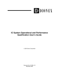
Digital Remote Controller for Duct Heater Use (KRC47-4)
1. Digital Remote Controller
AUTO
HEAT
HIGH
MED
COOL
LOW
POWER
FAN
TEMP +
TEMP -
For other parts 2. Holder, 3. Control Board (Box), 4. Wire Cable will be the same as KRC 47-2.
(P0007)
FDMG-AV1(S) Series
11
Optional Accessories
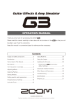
5.1.5
ED40-437
Internal Wiring Diagram
KRC47-1
ELECTRONIC
CONTROL
TEMPERATURE
CONTROL
CONTROL BOARD
« When select the high ESP,
connect the wire as shown
below.
OFF
ON
P1
P2
P3
P4
P5
P6
D
A
B
C
E
F
H
M
L
(ON/OFF)
L
N
P2
P3
P4
A
B
C
FDMG-AV1
Comp.
(THERMOSTAT)
FAN
«
(P0008)
KRC47-2
REMOTE CONTROLLER
THERMISTOR
CONTROL BOARD
P8
P9
« When select the high ESP,
connect the wire as shown
below.
FDMG-AV1
P4
P3
P2
P1
P7
F
E
A
B
C
D
N
L
(ON/OFF)
H
M
L
Comp.
(THERMOSTAT)
FAN
12
«
P3
P2
P1
A
B
C
(P0009)
FDMG-AV1(S) Series
ED40-437
Optional Accessories
KRC47-4
REMOTE CONTROLLER
THERMISTOR
CONTROL BOARD
P8
P9
« When select the high ESP,
connect the wire as shown
below.
FDMG-AV1
P4
P3
P2
P1
P7
F
E
A
B
C
D
N
L
(ON/OFF)
H
M
L
FAN
Comp.
(THERMOSTAT)
P6
P3
P2
P1
A
B
C
DUCT HEATER
(FIELD SUPPLIED)
«
(P0010)
FDMG-AV1(S) Series
13
Dimensions
ED40-437
6. Dimensions
6.1
Indoor Unit
FDMG71AV1(S)
Unit (mm)
3D048933A
FDMG100AV1(S)
FDMG125AV1(S)
FDMG140AV1(S)
Unit (mm)
3D048934A
14
FDMG-AV1(S) Series
ED40-437
Dimensions
FDMG180AV1(S)
Unit (mm)
3D048935A
FDMG-AV1(S) Series
15
Dimensions
6.2
ED40-437
Outdoor Unit
RG71AV1(S)
RG71AY1(S)
Unit (mm)
3D001674A
R100 · 125FUV1(S)
R100 · 125FUY1(S)
Unit (mm)
3D001672A
16
FDMG-AV1(S) Series
ED40-437
Dimensions
RG140AY1(S)
RG180AY1(S)
Unit (mm)
C : 3D027710A
FDMG-AV1(S) Series
17
Dimensions
6.3
ED40-437
Installation Service Space
3D001951A-1
18
FDMG-AV1(S) Series
ED40-437
Dimensions
3D001951A-2
FDMG-AV1(S) Series
19
Piping Diagrams
ED40-437
7. Piping Diagrams
7.1
Indoor Unit + Outdoor Unit
FDMG71A + RG71A
FDMG100A + R100FU
FDMG125A + R125FU
3D049457
FDMG140A + RG140A
FDMG180A + RG180A
3D049434
20
FDMG-AV1(S) Series
ED40-437
Wiring Diagrams
8. Wiring Diagrams
8.1
Indoor Unit
FDMG71AV1
FDMG100AV1
FDMG125AV1
FDMG140AV1
FDMG180AV1
8.2
Indoor Unit (For Thailand)
FDMG71AV1S
FDMG100AV1S
FDMG125AV1S
FDMG140AV1S
FDMG180AV1S
FDMG-AV1(S) Series
21
Wiring Diagrams
8.3
ED40-437
Outdoor Unit
RG71AV1
RG71AY1
22
FDMG-AV1(S) Series
ED40-437
Wiring Diagrams
R100FUV1
3D010788
R100FUY1
R125FUY1
3D001007C
FDMG-AV1(S) Series
23
Wiring Diagrams
ED40-437
RG140AY1
RG180AY1
8.4
Outdoor Unit (For Thailand)
RG71AV1S
24
FDMG-AV1(S) Series
ED40-437
Wiring Diagrams
RG71AY1S
R100FUV1S
FDMG-AV1(S) Series
25
Wiring Diagrams
ED40-437
R100FUY1S
R125FUY1S
RG140AY1S
RG180AY1S
26
FDMG-AV1(S) Series
ED40-437
8.5
Wiring Diagrams
Field Wiring
C : 4D049499
FDMG-AV1(S) Series
27
Capacity Table
ED40-437
9. Capacity Table
9.1
50Hz
FDMG71AV1 + RG71AV1
FDMG71AV1 + RG71AY1
3D049370
FDMG100AV1 + R100FUV1
FDMG100AV1 + R100FUY1
3D049352
28
FDMG-AV1(S) Series
ED40-437
Capacity Table
FDMG125AV1 + R125FUY1
3D049353
FDMG140AV1 + RG140AY1
3D049354
FDMG-AV1(S) Series
29
Capacity Table
ED40-437
FDMG180AV1 + RG180AY1
3D049361
9.2
50Hz (For Thailand)
FDMG71AV1S + RG71AV1S
FDMG71AV1S + RG71AY1S
3D049495
30
FDMG-AV1(S) Series
ED40-437
Capacity Table
FDMG100AV1S + R100FUV1S
FDMG100AV1S + R100FUY1S
3D049494
FDMG125AV1S + R125FUY1S
3D049496
FDMG-AV1(S) Series
31
Capacity Table
ED40-437
FDMG140AV1S + RG140AY1S
3D049497
FDMG180AV1S + RG180AY1S
3D049498
32
FDMG-AV1(S) Series
ED40-437
9.3
Capacity Table
Capacity Correction Factor by the Length of Refrigerant Piping
The cooling capacity of the unit has to be corrected in accordance with the length of refrigerant piping.
(The distance between the indoor unit and the outdoor unit)
Reference Data
100
71 · 125
140
180
3D049405
FDMG-AV1(S) Series
33
Fan Performance
ED40-437
10. Fan Performance
FDMG71A
4D049493
FDMG100A
4D049487
34
FDMG-AV1(S) Series
ED40-437
Fan Performance
FDMG125A
4D049488
FDMG140A
4D049489
FDMG-AV1(S) Series
35
Fan Performance
ED40-437
FDMG180A
4D049490
36
FDMG-AV1(S) Series
ED40-437
Operation Limit
11. Operation Limit
11.1
50Hz
3D049299A
11.2
50Hz (For Thailand)
3D049481
FDMG-AV1(S) Series
37
Sound Level
ED40-437
12. Sound Level
12.1
Overall Sound Level
12.1.1 Indoor Unit
dB(A)
Model
220V
240V
H
L
H
L
FDMG71AV1(S)
42
38
43
39
FDMG100AV1(S)
44
36
45
39
FDMG125AV1(S)
45
37
46
40
FDMG140AV1(S)
46
36
47
38
FDMG180AV1(S)
47
37
48
39
Measuring Location
4D049441
12.1.2 Outdoor Unit
dB(A)
Model
220V
RG71AV1(S)
R100FUV1(S)
56
Model
380V
RG71AY1(S)
52
R100FUY1(S)
56
R125FUY1(S)
Model
57
380V
415V
RG140AY1
55
57
RG180AY1
56
Model
38
Measuring Location
52
58
Microphone
4D002309
380V
RG140AY1S
58
RG180AY1S
59
FDMG-AV1(S) Series
ED40-437
12.2
Sound Level
Octave Band Level
12.2.1 Indoor Unit
FDMG71AV1(S)
FDMG100AV1(S)
4D049441
FDMG140AV1(S)
FDMG125AV1(S)
4D049442
FDMG180AV1(S)
4D049427
Note:
220V
240V
4D049431
FDMG-AV1(S) Series
4D049433
39
Sound Level
ED40-437
12.2.2 Outdoor Unit
RG71AV1(S)
RG71AY1(S)
R100FUV1(S)
R100FUY1(S)
RG180AY1
RG140AY1S
4D049426
RG180AY1S
4D002417
4D002416
4D002309
RG140AY1
R125FUY1(S)
4D049423
4D049502
Note:
Y1(S) : 380V
Y1 : 415V
4D049501
40
FDMG-AV1(S) Series
ED40-437
Electric Characteristics
13. Electric Characteristics
3D049371
FDMG-AV1(S) Series
41
Field Piping
ED40-437
14. Field Piping
14.1
Field Piping
14.1.1 Maximum Allowable Piping Length and Level Difference
RG71A, R100FU · 125FU, RG140A · 180A
Max. Allowable Piping Length
50 m (Equivalent Length 70 m)
Max. Allowable Level Difference
30 m
14.1.2 Additional Refrigerant Charge
y This unit requires additional charging of refrigerant according to the length of pipe connected at the site.
The range where no charging is required. (RG71A, R100FU · 125FU, RG140A · 180A : 5 m or less.)
Take the following steps for proper charging.
When connected to indoor unit
y Select the amount of refrigerant which matches a length which exceeds the charge-less length from
Table 1 and 2, and add it.
Write down the amount of extra refrigerant added in accordance with the precaution plate on the rear
surface of the front plate, as this is necessary for after-sales service.
RG71A, R100FU · 125FU
<Unit : kg>
Table 1 (The maximum allowable pipe length is 50 meters.)
Length of Pipe Connected (L)
5m
10m
15m
20m
25m
30m
35m
40m
45m
50m
Additional Charging Amount
—
0.13
0.25
0.38
0.50
0.63
0.75
0.88
1.00
1.13
RG140A · 180A
Table 2 Additional charging refrigerant amount
Additional charging
refrigerant amount
kg
=
Piping
length (L)
— 5m 0.025 kg/m
m
<PRECAUTION>
y Contact your DAIKIN dealer when installing the unit using pipes of 3 m or less.
14.1.3 Recharging Refrigerant
RG71A, R100FU · 125FU, RG140A · 180A
When the entire refrigerant pipe length is within 5 meters, charge the refrigerant in accordance with the
amount mentioned on the nameplate, and when the pipe length exceeds 5 meters, the charging amount is
an addition of the amount stated on the nameplate and the additional charging amount.
1PN06338-1-1
1PN01324-1A-1
3PN06106-3C-1
42
FDMG-AV1(S) Series
ED40-437
Field Piping
14.1.4 Pumping-down Operation Method
Take the following steps to perform the pumping-down operation.
1. In case of RG71A, R100FU · 125FU
Procedure
Precautions
1. Connect a pressure gauge to the service port of the
stop valve.
Carry out an air purge of the charge hose.
2. Perform fan operation by the remote controller.
Make sure that the liquid-side and gas-side stop valves
are fully open.
3. Perform cooling operation by the remote controller.
Check that the compressor and outdoor fan are
operation.
4. Run the unit for one minute until the operation
stabilizes.
—
5. Close the liquid-side stop valve fully. (Refer to Fig.1) If the valve is not fully closed it could cause burn-out of
the compressor.
6. After the pressure gauge indication has dropped to 0
kgf/cm2G, close the gas stop valve fully and press
the Stop button on the remote controller.
—
This is the end of pumping-down operation.
Caution:
2. In case of RG140A · 180A
Never short-circuit the low-pressure switch in this operation.
Procedure
Precautions
1. Perform cooling operation by the remote controller.
Confirm that stop valves both on the liquid and gas side
are opened.
Check that the compressor and outdoor fan are
operating.
2. Continue operation for 1 minute until operation
condition stabilizes.
—
3. Close the liquid-side stop valve fully. (Refer to Fig. 1) Insecure closing of this valve may result in burning of
the compressor.
4. When the low-pressure switch is activated, the unit
stops working. At this time, close the stop valve on
the gas side.
—
5. Turn off the remote controller.
—
This is the end of pumping-down operation.
Necessity of a trap
Since there is fear of the oil held inside the riser piping
flowing back into the compressor when stopped and
causing liquid compression phenomenon, or cases of
deterioration of oil return, it will be necessary to provide a
trap at an appropriate place in the riser gas piping.
Trap installation spacing
Indoor unit
Oil trap
Gas piping
Liquid piping
Outdoor unit
Note:
FDMG-AV1(S) Series
A trap is not necessary when the outdoor unit is installed in a higher position than the indoor unit.
43
Field Piping
ED40-437
Caution to be taken when brazing refrigerant piping
“Do not use flux when brazing copper-to-copper refrigerant piping. (Particularly for the HFC refrigerant
piping) Therefore, use the phosphor copper brazing filler metal (BCuP) which does not require flux”.
(Flux has extremely harmful influence on refrigerant piping systems. For instance, if the chlorine based
flux is used, it will cause pipe corrosion or, in particular, if the flux contains fluorine, it will damage the
refrigerant oil. The use of flux is strictly forbidden since the cleaning on site is impossible.)
(Remark) Keep in mind that if the phosphor copper brazing filler metal is used and the brazing
temperature and the heating time exceed a certain point, the phoshor changes into the
gaseous state
(e.g . BCuP -1 to 5 : between 700 and 800°C) which causes pin holes and results in
refrigerant leakage.
1PN06338-1-2
1PN01324-1A-2
3PN06106-3C-2
44
FDMG-AV1(S) Series
ED40-437
Installation
15. Installation
15.1
FDMG-AV1(S) Series
INSTALLING THE INDOOR UNIT
1
Selecting the Location
■ Select an installation site that fulfills the following conditions and meets the customer’s approval.
Units : mm
Optimum air distribution is ensured.
The air passage is not blocked.
Condensate can drain properly.
The ceiling is strong enough to bear the weight of the indoor unit.
A false ceiling does not seem to be at an incline.
300 or more
Sufficient clearance for maintenance and servicing is ensured.
Piping between the indoor and outdoor units is within the allowable
(Service space)
limits. (Refer to the installation manual for the outdoor unit.)
• The indoor unit, outdoor unit, power supply wiring and transmission
Ceiling
wiring is at least 1 meter away from televisions and radios. This
NOTES) • Above H* is the minimum size of the indoor unit.
prevents image interference and noise in electrical appliances.
• Extra 20-30 mm is necessary to connect gas pipes.
(Noise may be generated depending on the conditions under which
Determine size H* based on 1/100 of the required
the electric wave is generated, even if a one-meter allowance is
downward inclination indicated in “DRAIN PIPING
maintained.)
WORK”.
• Ambient air of the indoor unit is not so dusty.
Drain piping may be clogged with dust and may result in water leakage and property damage.
(When obliged to install the indoor unit in a dusty place, install the
optional Dust Cover which prevent dust from falling into drain pan.)
10 or more
H* 325 (Min.)
•
•
•
•
•
•
•
■ When exposing the body of this unit, install the unit where
the bottom is move than 2.5 m high so that the user can not
touch.
■ Use suspension bolts to install the unit. Check whether or
not the ceiling is strong enough to support the weight of
the unit. If there is a risk that the ceiling is not strong
enough, reinforce the ceiling before installing the unit.
2
400 or more
Gas pipe
(
Wiring port
Liquid pipe
In case of
bottom
suction
)
Drain pipe
Preparations Before Installation
■ Relation of the unit to the suspension bolt positions
Units : mm
55
Model
B
1203
1350
FDMG100 · 125 · 140AV1
1403
1550
FDMG180AV1
1753
1900
680
A
FDMG71AV1
Suspension bolt (M10x4)
(Suspension bolt pitch)
600
Units : mm
126
(Suspension bolt pitch)
A
B
(Installation example)
■ Install the suspension bolts.
(Use M10-size bolts for the suspension bolts.)
In order to reinforce the ceiling bearing the weight of the unit, use anchors
when installing onto an existing ceiling or use sunken inserts, sunken
anchors or other commercially available parts when installing onto a new
ceiling.
Ceiling slab
Anchor
Long nut or turn-buckle
Suspension bolt
Indoor unit
NOTE) All of the above parts are commercially available.
1PN06319-1B-1
FDMG-AV1(S) Series
45
Installation
3
ED40-437
Indoor Unit Installation
■ While installing unit, take care that dust etc. should not drop into the
drain pan.
Nut (commercially available)
Washer 7
■ Temporarily install the indoor unit.
• Attach the hanger brackets to the suspension bolts. Be sure to use nuts and
washers both above and below the hanger brackets to secure them.
Tighten
(two nuts)
■ Use a water level or water-filled vinyl tubes to check that the unit is
level at all four corners as shown in the drawing.
■ Tighten the top nuts.
Water level
Vinyl tubes
4
Refrigerant Piping Work
See the installation manual attached to the outdoor unit.
The outdoor unit is charged with refrigerant.
■ Providing the connecting piping between the indoor unit and the outdoor unit
Table 1
Flare shape
12.0 to 12.4
15.4 to 15.8
± 2˚
8.3 to 8.7
R0.4 to 0.8
45˚
1420 to 1720N·cm
ø6.4
(144 to 176kgf·cm)
3270 to 3990N·cm
ø9.5
(333 to 407kgf·cm)
4950 to 6030N·cm
ø12.7
(504 to 616kgf·cm)
6180 to 7540N·cm
ø15.9
(630 to 770kgf·cm)
9720 to 11860N·cm
ø19.1
(990 to 1210kgf·cm)
Flare dimension
B (mm)
18.6 to 19.0
22.9 to 23.3
Sealing pad 5
(Wrap the piping union with the sealing pad.)
Insulation for fitting 3 (for gas piping)
Pipe fixing plate
Insulation for fitting 4 (for liquid piping)
Liquid piping (with insulation)
Gas piping (with insulation)
To outdoor unit
Clamp 6
(x4)
Pipe
gauge Tightening torque
B
• Be sure to use both a spanner
and a torque wrench together,
as shown in the drawing, when
Spanner connecting pipes to or
disconnecting them from the
unit.
• When connecting the flare nut,
Piping union
coat both the inside and
outside with refrigerent
Flare nut
machine oil. Then, tighten it 3
or 4 turns by hand before
tightening it firmly.
• Refer to Table 1 to determine
Coat here with
the power tightening torque.
refrigerating
(Overtightening may damage
machine oil.
the flare and cause leaks.)
• Check the pipe connections for
gas leaks.
90˚ ± 0.5˚
Torque wrench
• Install the insulation as shown in the drawing above.
(Install the insulation for the fittings attached to the pipe fixing plate.)
• Wrap the sealing pad 5 around only the union of the gas piping (over the
insulation for fitting 3 ).
1PN06319-1B-2
46
FDMG-AV1(S) Series
ED40-437
5
Installation
Drain Piping Work
■ Connect the drain pipe as described below.
•
•
•
•
It is necessary to clean the drain pan.
The drain pipe outlet can be either on the right or left side.
After making the connection, wrap the drain pipes completely with insulation.
When connecting the drain pipe to the outlet on the left side, remove the rubber plug and attach it to the outlet on the right side.
Do not raise.
Drain pipe (3/4 B)
Do not bend.
Rubber plug
Nominal diameter 26
Completely insulate.
Completely insulate.
Do not leave
in water.
Units: mm
■ Pour some water into the drain pan to check that the water drains smoothly.
■ Make sure that water does not leak from the drain piping,
connecting parts and the drain plug.
6
Watering can
Wiring
See the installation manual attached to the outdoor unit.
CAUTION
Ground the air conditioner.
When grounding the air conditioner, use a ground wire of 100 Ω or less.
■ Field wiring connection method
For details, follow the local applicable laws and regulations concerning electrical installations.
NOTE) A commercially available remote controller can be used if its specifications are compatible with those shown in the wiring
diagram and technical materials.
CAUTION
Be sure to use a 3-minute delay timer when starting the compressor,
otherwise the compressor may not start.
• When using a commercially available three speed remote
controller, refer to the following.
NOTE)Refer to the wiring diagram and to the installation manual of the remote controller.
Fan speed control
Line
Neutral
L
Comp.
H
M
A B C D E F
1 2 3
Apply clamp 6 to wiring
so as not to slide
even if wiring is pulled.
Earth
terminal
Surely fasten wiring
by clamp 6 .
Indoor unit
To remote controller
Ground
To outdoor unit
Securely fasten each wire clamp with a screw.
1PN06319-1B-3
FDMG-AV1(S) Series
47
Installation
ED40-437
Remote controller
The indoor unit has the
Fuse (5A).
Select the interconnection cable size with the
Fuse (5A).
: Optional accessory
Power supply
VAL-1PH : 60Hz, 220V
V1-1PH : 50 Hz, 220 to 240V
The Fuse for interconnection cable is
not built into outdoor unit.
Select the interconnection cable size
with Field fuse.
Securely fasten the wire plates
with screws.
1 2 3
Ground
leakage
breaker
Safety breaker :
See details in the
installation manual
attached to the
outdoor unit.
L N
Outdoor unit
• When using the optional KRC47-1 or the KRC47-2 remote controllers, which have three fan speed settings, refer to the
following.
Neutral → F
Line → E
Low → C
Medium→B
High→A
Comp. → D
To indoor unit
Remote Controller
For more details, please see the manual of remote controller.
• Use ring type terminals for connections to the power supply
terminal block.
Where they can not be used, refer to the following.
• Observe the notes mentioned below while connecting wire to the
power supply terminal board.
Do not connect wires of different gauges to the same power
supply terminal.
(Looseness in the connection may cause overheating.)
When connecting wires of the same gauge, connect them
according to the figure on the right.
Wire
Ring type terminal
Connect wires
of the same
gauge on both
sides.
Do not connect
wires of the same
gauge to only one
side.
Do not connect
wires of different
gauges.
• Indoor unit
Terminal block
Earth terminal
Wire clamp
1PN06319-1B-4
48
FDMG-AV1(S) Series
ED40-437
7
Installation
Finishing the Piping Connections
After applying paste, attach the surface
cover (commercially available).
Paste. (Fill the gaps in the wall hole with
the paste supplied with the piping kit.)
Wind the finishing tape around the
piping from the bottom to the top.
Fasten the pipes with retainers at
intervals of 1.5 or 2 m.
Cut the heat-insulating tube to the required
length and wrap it with the finishing tape to
eliminate the gap between the heatinsulating tube and the pipes.
Thermal insulation should also be provided
for the outdoor unit connections.
INSTALLING THE OUTDOOR UNIT
<See the installation manual attached to the outdoor unit.>
C : 1PN06319-1B-5
FDMG-AV1(S) Series
49
Warning
Ask a qualified installer or contractor to install this product. Do not try to install the product yourself.
Improper installation can result in water or refrigerant leakage, electrical shock, fire or explosion.
Use only those parts and accessories supplied or specified by Daikin. Ask a qualified installer or
contractor to install those parts and accessories. Use of unauthorized parts and accessories or
improper installation of parts and accessories can result in water or refrigerant leakage, electrical
shock, fire or explosion.
Read the User's Manual carefully before using this product. The User's Manual provides important
safety instructions and warnings. Be sure to follow these instructions and warnings.
For any inquiries, contact your local distributor.
Cautions on product corrosion
1. Air conditioners should not be installed in areas where corrosive gases, such as acid gas or alkaline gas, are produced.
2. If the outdoor unit is to be installed close to the sea shore, direct exposure to the sea breeze should be avoided and choose an
outdoor unit with anti-corrosion treatment.
The air conditioners manufactured
by Daikin Industries have received
ISO 9001 certification for quality
assurance.
Certificate Number. JMI-0107
JQA-0495
JQA-1452
All Daikin Industries locations and
subsidiaries in Japan have
received environmental
management system standard
ISO 14001 certification.
Daikin Industries, Ltd.
Domestic Group
Certificate Number. EC99J2044
About ISO 14001
ISO 14001 is the standard defined by the International
Organization for Standardization (ISO) relating to
environmental management systems. Our group has
been acknowledged by an internationally accredited
compliance organisation as having an appropriate
programme of environmental protection procedures
and activities to meet the requirements of ISO 14001.
Dealer
Head Office:
Umeda Center Bldg., 2-4-12, Nakazaki-Nishi,
Kita-ku, Osaka, 530-8323 Japan
Tokyo Office:
JR Shinagawa East Bldg., 2-18-1, Konan,
Minato-ku, Tokyo, 108-0075 Japan
http://www.daikin.com/global/
c All rights reserved
The specifications, designs, and information in this brochure are subject to change without notice.
This book is made of recycled paper.
ED 40-437
Printed in Japan 06/2005 FS