1
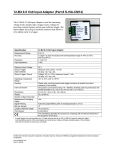
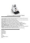
User's Manual for BT656Pro SDI Mod. Kit PMS Video Ltd. Doc No: PMS-UM0006 Rev. 1.0 Last update: 18/06/2004 1. Warning: It is assumed that you have already fully understood the pin assignments of the MPEG decoder in your DVD player / set-top box and have the skill to do the modification. PMS Video Ltd. is not responsible for any damage caused during the modification. 2. Introduction: The BT656Pro SDI Mod. Kit converts the standard parallel BT656 digital video signal generated by the MPEG decoders of DVD players or set-top boxes to SDI (Serial Digital Interface) signal for video signal transmission in order to avoid unnecessary digital-to-analog and analog-to-digital conversions which will cause video quality loss. SDI can keep video signal digital, from the source to the video processor / scaler then to the digital displays, i.e. the highest video picture quality. 2. Features: Standard compliant SDI output, compatible with major SDI capture devices Supports major DVD players and set-top boxes with ITU BT656 video output Provides 1 SDI output One BNC connector is pre-installed for easy installation Provides fully digital output directly from a MPEG decoder to SDI capture card/video processor Status LED turns on when 27MHz clock signal is detected 30AWG wire wrap wires and power cable are included to facilitate the installation 3. System Requirements: -The video signal from the MPEG decoder must be ITU BT656 compliant (8-bit video data with embedded sync + 27MHz video clock). -DC 5V (usually provided by the DVD player or the set-top box) is required to power the kit. 4. Specifications: -Dimensions (H x W x D): 1.5cm x 5cm x 4cm, 1.5cm x 7cm x 4cm including the BNC connectors -Power consumption: 0.3W -One Serial Digital Interface (SDI) Output -One BT656 Input LED Indicator -PIN assignments: - LED (D2) lights up when 27MHz clock signal is detected. - D0 & D1 are for 10-bits SDI applications, they are not used for DVD/set top box SDI modification. - 8bits (D2-D9). - D2 is the less significant bit. - D9 is the most significant bit. - Clock - Ground (Twisted clock and ground cable may lower the noise of the clock signal) - +5 V. - Ground 6. Installation: 1. 2. Connect all D2-D9 pins to the appropriate MPEG decoder output pins of your DVD player or set-top box. The D0 and D1 pins are not used because the digital video output of the MPEG decoders in the DVD players and set-top boxes is 8-bit data only. Connect the 5 volt and ground to the appropriate location on the circuit board of the DVD player or set-top box. 7. Finish: 1. 2. After the modification, power up the DVD player or set-top box and the LED (D2) on the kit should light up indicating that it is receiving a 27MHz clock signal from the MPEG decoder of the DVD player or set-top box. Connect BNC cables from the SDI output of this Mod. Kit to your SDI capture device. Example: An SDI Mod. Kit installed on a Panasonic RP82 DVD player is shown in the following picture. Example: the pin assignment of RP82's MPEG2 decoder