1
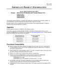
8 IC693APU301/302 Motion Mate Axis Positioning Module (APM) The Motion Mate APM is an easy-to-use intelligent, fully programmable one-axis (IC693APU301) or two-axis (IC693APU302) motion control module for the Series 90-30 PLC. The APM allows a PLC user to combine high-performance control with PLC logic solving functions in one integrated system. The APM can be configured to operate in either Standard mode or Follower mode. When used in Standard mode, it combines high-performance motion control with PLC logic solving functions in one integrated system. When used in Follower mode, it provides high-performance “electronic gearing” for continuous master/slave applications. The desired mode is easily selected by configuring a setup parameter in the configuration software. EN1 STAT EN2 OK AXIS POS MODULE CFG ONE AXIS C O M M B A Figure 8-10. Motion Mate APM Module The Series 90-30 and APM operate together as one integrated motion control package. The APM controls axis motion and handles all direct communications to the drive and machine while the PLC automatically transfers data between PLC tables and the APM. The PLC also provides a means for connecting Operator Interfaces, which can control and monitor system operation. An example of an APM servo system showing the hardware and software used to configure, program, and operate the system is shown below. The APM can be installed in any Series 90-30 CPU, expansion, or remote baseplate. For embedded CPUs (311, 313, or 323), you may have up to three APM modules. For a modular CPU (331 or higher), you may have up to eight APM modules in one system, with a maximum of three APM modules per baseplate. Multiple motion programs may be created and stored in the APM (maximum of 10 may be stored in the APM) with the Motion Programmer software package. The APM is configured and programmed with VersaPro software (Version 1.1 or later) or Logic Developer-PLC. GFK-0356Q Chapter 8 Option Modules 8-15 8 The APM faceplate (front panel) has two 24-pin high-density connectors for servo connections. The connector labeled A contains connections for Axis 1. Connector B, for a 1-axis APM, contains general purpose connections. Connector B, for a 2-axis APM, has connections for Axis 2 as well general purpose connections. To make wiring easier to the drive and machine, each high-density connector is typically connected by a short cable to a terminal block. CPU MACHINE 1 APM DRIVE ENCODER 1 MACHINE 2 DRIVE Configuration Software Motion Programming Software ENCODER 2 Figure 8-11. Example of Motion Mate APM Servo System APM Cables These cables consists of a 24-pin I/O connector , a cable, and a 25-pin D-type terminal block connector. (Cables are documented in Chapter 10.) Available cables are: IC693CBL311 (10 feet/3 meters) IC693CBL319 (3 feet/1 meter) IC693CBL317 (10 feet/3 meters) with an 8” external shield pigtail C693CBL320 (3 feet/1 meter) with an 8” external shield pigtail For building custom-length cables, the 24-pin I/O cable connector is available in three different kits (solder eyelet receptacle, crimp wire receptacle, and IDC (ribbon) receptacle). The terminal block is Weidmuller RD25 910648 or equivalent (must be compatible with the I/O cable IC693CBL311/319/317/320 - see Chapter 10 for details). Motion Mate APM Module Documentation See the following manuals for detailed information on Power Mate APM Modules: GFK-0840 Motion Mate APM for Series 90-30 PLC Standard Mode User’s Manual GFK-0781 Motion Mate APM for Series 90-30 PLC Follower Mode User’s Manual GFK-0664 Series 90 PLC APM Programmer’s Manual Related servo manual: 8-16 GFK-1581 SL Series Servo User’s Manual Series 90-30 PLC Installation and Hardware Manual – August 2002 GFK-0356Q