1
Wind Power Inverter
WINDY BOY 3300 / 3800
Installation Guide
WB33_38-IEN101830 | IME-WB3800 | Version 3.0
EN
SMA Solar Technology AG
Table of Contents
Table of Contents
1
1.1
1.2
1.3
1.4
Notes on this Guide . . . . . . . . . . . . . . . . . . . . . . . . . . . . . . .
Validity . . . . . . . . . . . . . . . . . . . . . . . . . . . . . . . . . . . . . . . . . . . .
Target Group . . . . . . . . . . . . . . . . . . . . . . . . . . . . . . . . . . . . . . .
Additional Information . . . . . . . . . . . . . . . . . . . . . . . . . . . . . . . .
Symbols Used . . . . . . . . . . . . . . . . . . . . . . . . . . . . . . . . . . . . . . .
2
2.1
2.2
2.3
Safety . . . . . . . . . . . . . . . . . . . . . . . . . . . . . . . . . . . . . . . . . . 9
Appropriate Usage . . . . . . . . . . . . . . . . . . . . . . . . . . . . . . . . . . . 9
Safety Precautions. . . . . . . . . . . . . . . . . . . . . . . . . . . . . . . . . . . 10
Explanation of Symbols . . . . . . . . . . . . . . . . . . . . . . . . . . . . . . 10
2.3.1
Symbols on the Inverter. . . . . . . . . . . . . . . . . . . . . . . . . . . . . . . . . . . . . . . . . 10
2.3.2
Symbols on the Type Label . . . . . . . . . . . . . . . . . . . . . . . . . . . . . . . . . . . . . . 11
3
3.1
3.2
Unpacking. . . . . . . . . . . . . . . . . . . . . . . . . . . . . . . . . . . . . . 12
Scope of Delivery . . . . . . . . . . . . . . . . . . . . . . . . . . . . . . . . . . . 12
Identifying the Inverter . . . . . . . . . . . . . . . . . . . . . . . . . . . . . . . 13
4
4.1
4.2
4.3
Mounting the Device . . . . . . . . . . . . . . . . . . . . . . . . . . . . . 14
Safety . . . . . . . . . . . . . . . . . . . . . . . . . . . . . . . . . . . . . . . . . . . . 14
Selecting the Mounting Location. . . . . . . . . . . . . . . . . . . . . . . . 15
Mounting the Inverter with the Wall Mounting Bracket . . . . . . 17
5
5.1
5.2
Electrical Connection . . . . . . . . . . . . . . . . . . . . . . . . . . . . . 20
Safety . . . . . . . . . . . . . . . . . . . . . . . . . . . . . . . . . . . . . . . . . . . . 20
Overview of the Connection Area . . . . . . . . . . . . . . . . . . . . . . 20
5.2.1
Exterior View . . . . . . . . . . . . . . . . . . . . . . . . . . . . . . . . . . . . . . . . . . . . . . . . . 20
5.2.2
Interior View . . . . . . . . . . . . . . . . . . . . . . . . . . . . . . . . . . . . . . . . . . . . . . . . . 21
5.3
Connection to the Public Grid (AC) . . . . . . . . . . . . . . . . . . . . . 22
5.3.1
Connecting the Inverter to the Public Grid (AC) . . . . . . . . . . . . . . . . . . . . . . 24
5.4
Setting the Display Language . . . . . . . . . . . . . . . . . . . . . . . . . . 27
Installation Guide
WB33_38-IEN101830
7
7
7
7
8
3
Table of Contents
SMA Solar Technology AG
5.5
Connecting the Small Wind Turbine System (DC) . . . . . . . . . . 28
5.5.1
Conditions for the DC Connection . . . . . . . . . . . . . . . . . . . . . . . . . . . . . . . . 28
5.5.2
Assembling the PV connector . . . . . . . . . . . . . . . . . . . . . . . . . . . . . . . . . . . . 29
5.5.3
Opening the PV connector . . . . . . . . . . . . . . . . . . . . . . . . . . . . . . . . . . . . . . 31
5.5.4
Connecting the Small Wind Turbine System (DC). . . . . . . . . . . . . . . . . . . . . 32
5.6
5.7
Communication. . . . . . . . . . . . . . . . . . . . . . . . . . . . . . . . . . . . . 33
Setting the Grid and Country Parameters . . . . . . . . . . . . . . . . . 33
5.7.1
5.7.2
Setting the Installation Country . . . . . . . . . . . . . . . . . . . . . . . . . . . . . . . . . . . 33
Setting Off-Grid Operation . . . . . . . . . . . . . . . . . . . . . . . . . . . . . . . . . . . . . . 34
5.8
Polynomial Characteristic Curve . . . . . . . . . . . . . . . . . . . . . . . . 35
6
6.1
6.2
Commissioning . . . . . . . . . . . . . . . . . . . . . . . . . . . . . . . . . . 36
Commissioning the Inverter . . . . . . . . . . . . . . . . . . . . . . . . . . . . 36
Self-Test in accordance with DK 5940, Ed. 2.2
(Applies to Italy Only). . . . . . . . . . . . . . . . . . . . . . . . . . . . . . . . 37
6.2.1
Starting the Self-Test by Tapping . . . . . . . . . . . . . . . . . . . . . . . . . . . . . . . . . . 37
6.2.2
Completion of the Self-Test . . . . . . . . . . . . . . . . . . . . . . . . . . . . . . . . . . . . . . 37
6.3
Operating Conditions of the Inverter . . . . . . . . . . . . . . . . . . . . 42
7
7.1
7.2
7.3
Opening and Closing. . . . . . . . . . . . . . . . . . . . . . . . . . . . . 43
Safety . . . . . . . . . . . . . . . . . . . . . . . . . . . . . . . . . . . . . . . . . . . . 43
Opening the Inverter. . . . . . . . . . . . . . . . . . . . . . . . . . . . . . . . . 44
Closing the Inverter . . . . . . . . . . . . . . . . . . . . . . . . . . . . . . . . . . 45
8
8.1
Maintenance and Cleaning . . . . . . . . . . . . . . . . . . . . . . . . 47
Checking Heat Dissipation . . . . . . . . . . . . . . . . . . . . . . . . . . . . 47
8.1.1
Cleaning the Fan. . . . . . . . . . . . . . . . . . . . . . . . . . . . . . . . . . . . . . . . . . . . . . 47
8.1.2
Checking the Fan . . . . . . . . . . . . . . . . . . . . . . . . . . . . . . . . . . . . . . . . . . . . . 48
8.1.3
Cleaning the Air Grills. . . . . . . . . . . . . . . . . . . . . . . . . . . . . . . . . . . . . . . . . . 50
9
9.1
9.2
Troubleshooting . . . . . . . . . . . . . . . . . . . . . . . . . . . . . . . . . 51
Blink Codes. . . . . . . . . . . . . . . . . . . . . . . . . . . . . . . . . . . . . . . . 51
Error Messages. . . . . . . . . . . . . . . . . . . . . . . . . . . . . . . . . . . . . 52
4
WB33_38-IEN101830
Installation Guide
SMA Solar Technology AG
Table of Contents
9.3
Red LED is Glowing Continuously. . . . . . . . . . . . . . . . . . . . . . . 57
9.3.1
Checking the Small Wind Turbine System for a Ground Fault . . . . . . . . . . . 57
9.3.2
Checking the Functioning of the Varistors . . . . . . . . . . . . . . . . . . . . . . . . . . . 59
10
10.1
10.2
10.3
10.4
Decommissioning . . . . . . . . . . . . . . . . . . . . . . . . . . . . . . . . 61
Dismantling the Inverter. . . . . . . . . . . . . . . . . . . . . . . . . . . . . . . 61
Packing the Inverter. . . . . . . . . . . . . . . . . . . . . . . . . . . . . . . . . . 62
Storing the Inverter . . . . . . . . . . . . . . . . . . . . . . . . . . . . . . . . . . 62
Disposing of the Inverter . . . . . . . . . . . . . . . . . . . . . . . . . . . . . . 62
11
11.1
11.2
Technical Data . . . . . . . . . . . . . . . . . . . . . . . . . . . . . . . . . . 63
Windy Boy 3300 . . . . . . . . . . . . . . . . . . . . . . . . . . . . . . . . . . . 63
Windy Boy 3800 . . . . . . . . . . . . . . . . . . . . . . . . . . . . . . . . . . . 66
12
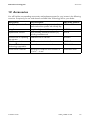
Accessories . . . . . . . . . . . . . . . . . . . . . . . . . . . . . . . . . . . . . 69
13
Contact . . . . . . . . . . . . . . . . . . . . . . . . . . . . . . . . . . . . . . . . 70
Installation Guide
WB33_38-IEN101830
5
Table of Contents
6
WB33_38-IEN101830
SMA Solar Technology AG
Installation Guide
SMA Solar Technology AG
Notes on this Guide
1 Notes on this Guide
This installation guide describes the assembly, installation, commissioning and maintenance of the
following SMA inverters:
• Windy Boy 3300 (WB 3300)
• Windy Boy 3800 (WB 3800)
Store this guide where it can be accessed at all times.
1.1 Validity
This guide applies to all device types WB 3300 and WB 3800 with firmware version 2.94, and later.
1.2 Target Group
This guide is for qualified personnel. The tasks described in this guide may only be performed by
qualified personnel.
1.3 Additional Information
You will find further information on special topics such as designing a line circuit breaker or the
description of the operating parameters in the download area at www.SMA.de/en.
Refer to the user manual for detailed information on operating the inverter.
Installation Guide
WB33_38-IEN101830
7
Notes on this Guide
SMA Solar Technology AG
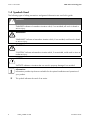
1.4 Symbols Used
The following types of safety precautions and general information are used in this guide:
DANGER!
"DANGER" indicates a hazardous situation which, if not avoided, will result in death or
serious injury.
WARNING!
"WARNING" indicates a hazardous situation which, if not avoided, could result in death
or serious injury.
CAUTION!
"CAUTION" indicates a hazardous situation which, if not avoided, could result in minor or
moderate injury.
NOTICE!
"NOTICE" indicates a situation that can result in property damage if not avoided.
Information
Information provides tips that are valuable for the optimal installation and operation of
your product.
☑
8
This symbol indicates the result of an action.
WB33_38-IEN101830
Installation Guide
SMA Solar Technology AG
Safety
2 Safety
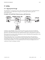
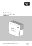
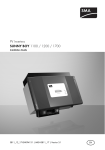
2.1 Appropriate Usage
The Windy Boy is a wind power inverter, which converts rectified current of a small wind turbine
system into AC current and feeds this energy into the public grid, domestic grid or the
Sunny Island system.
Principle of a Small Wind Turbine System with Windy Boy
Furthermore, the Windy Boy can be used as an inverter for power conversion units based on
permanent magnet generators (hydro power systems, combined heat and power plants, diesel
generators, etc.). The manufacturer of the small wind turbine system or the generator must have his
plant approved for operation with this Windy Boy (see also the Windy Boy planning guidelines in the
download area at www.SMA.de/en).
When designing the system, ensure that the permitted operating range of all components is
maintained at all times. Also use appropriate protective measures to ensure that the maximum
permissible input voltage of the inverter is not exceeded. SMA Solar Technology AG offers you the
corresponding components, such as the Windy Boy Protection Box (overvoltage protection for
wind power inverters including the rectifier).
Installation Guide
WB33_38-IEN101830
9
Safety
SMA Solar Technology AG
2.2 Safety Precautions
DANGER!
Electric shock due to high voltages in the inverter when connecting the device.
Death or serious injury.
• All work on the inverter may be carried out by qualified personnel only.
• The appliance is not to be used by children or persons with reduced physical,
sensoryor mental capabilities, or lack of experience and knowledge, unless they
have been given supervision or instruction.
• Children should be supervised to ensure that they do not play with the appliance.
• Work on the inverter must only be carried out as described in this guide.
• All safety instructions listed must be observed.
CAUTION!
Risk of burns through contact with the hot enclosure during operation. Burns to
the palm of the hand.
• Do not touch the inverter's enclosure during operation.
Problems while performing the described activities
If you have problems while performing any of the activities described in this guide, contact
SMA Solar Technology AG (see section 13 ”Contact” (page 70)).
2.3 Explanation of Symbols
This section contains an explanation of all symbols found on the inverter and type label.
2.3.1 Symbols on the Inverter
Symbol
Explanation
Operation display.
Indicates the operation condition of the inverter.
Ground fault or varistor defective.
There is either a ground fault in the system, or at least one of the varistors
inside the inverter is defective.
An error has occurred.
Read the installation guide and the user manual to remedy the malfunction.
Tap to switch on the display light and switch to the next message.
10
WB33_38-IEN101830
Installation Guide
SMA Solar Technology AG
Safety
2.3.2 Symbols on the Type Label
Symbol
Explanation
Beware of dangerous electrical voltage.
The inverter operates at high voltages. All work on the inverter may be
carried out by qualified personnel only.
Beware of hot surface.
The inverter can become hot during operation. Avoid contact during
operation.
Observe all documentation that accompanies the inverter.
The inverter must not be disposed of with household waste. For more
information on disposal, see section 10.4 ”Disposing of the Inverter”
(page 62).
CE mark.
The inverter complies with the requirements of the applicable
EC guidelines.
RAL quality mark for solar products.
The inverter complies with the requirements of the German Institute for
Quality Assurance and Labeling.
The inverter has a transformer.
Direct Current (DC).
Alternating Current (AC).
The inverter is protected against penetration by dust particles and water
jets from any angle.
Installation Guide
WB33_38-IEN101830
11
Unpacking
SMA Solar Technology AG
3 Unpacking
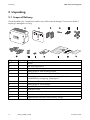
3.1 Scope of Delivery
Check the delivery for completeness and for any visible external damage. Contact your dealer if
anything is damaged or missing.
Object
A
B
C
D
E
F
Quantity
1
1
2
5
2
1
Description
Inverter
Wall mounting bracket
Air grills (1x left, 1x right)
Sealing plugs for wall mounting bracket
Cylinder head screw and contact disk (M6)
AC coupling socket: socket unit, protective cap for socket unit,
threaded sleeve, sealing ring, clamping nut.
PV connectors (3 x positive / 3 x negative)
Sealing plugs for PV connectors
Jumper for communication / fan test
Installation Guide
User Manual
Set of documents with explanations and certificates
Supplementary sheet with inverter factory settings
G
H
I
K
L
M
N
6
6
1
1
1
1
1
12
WB33_38-IEN101830
Installation Guide
SMA Solar Technology AG
Unpacking
3.2 Identifying the Inverter
You can identify the inverter using the type label. The type label is on the right side of the enclosure.
On the type label you will find the type (Type/Model) and the serial number (Serial No.) of the
inverter.
Installation Guide
WB33_38-IEN101830
13
Mounting the Device
SMA Solar Technology AG
4 Mounting the Device
4.1 Safety
DANGER!
Danger to life due to fire or explosion.
Despite careful construction, electrical devices can cause fires.
• Do not mount the inverter on flammable construction materials.
• Do not mount the inverter in areas where highly flammable materials are stored.
• Do not mount the inverter in areas with a risk of explosion.
CAUTION!
Danger of burn injuries due to hot enclosure parts.
• Do not touch the enclosure during operation.
CAUTION!
Risk of injury due to the heavy weight of the inverter.
• Note that the inverter weighs approx. 38 kg.
14
WB33_38-IEN101830
Installation Guide
SMA Solar Technology AG
Mounting the Device
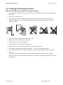
4.2 Selecting the Mounting Location
Observe the following conditions during mounting:
• The installation method and mounting location must be suitable for the inverter's weight and
dimensions.
• Mount on a solid surface.
• The mounting location must at all times be clear and have safe access without the use of
additional aids such as scaffolding or lifting platforms. Any possible service actions are
otherwise limited.
• Mount vertically or tilted backward by max. 45°.
• Never mount the device with a forward tilt.
• Do not mount in a horizontal position.
• The connection area must point downward.
• Install at eye level to allow operating state to be read at all times.
• The ambient temperature should be below 40 °C to ensure optimal operation.
• Do not expose the inverter to direct sunlight to avoid a power reduction due to excessive
heating.
• In living areas, do not mount the unit on plasterboard walls or similar to avoid audible
vibrations. The inverter can make noises when in use which may be perceived as a nuisance in
a living area.
Installation Guide
WB33_38-IEN101830
15
Mounting the Device
SMA Solar Technology AG
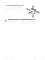
• Observe the minimum clearances to walls, other
inverters or objects as shown in the diagram in
order to guarantee sufficient heat dissipation.
Multiple inverters installed in areas with high ambient temperatures
If necessary, increase the clearances between the individual inverters. In addition, make
sure there is enough ventilation to ensure sufficient cooling of the inverters.
16
WB33_38-IEN101830
Installation Guide
SMA Solar Technology AG
Mounting the Device
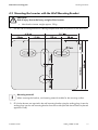
4.3 Mounting the Inverter with the Wall Mounting Bracket
CAUTION!
Risk of injury due to the heavy weight of the inverter.
• Note that the inverter weighs approx. 38 kg.
1. Use the wall mounting bracket as a drilling template and mark the positions of the drill holes.
Mounting material
When mounting the bracket, use fastening material suitable for the mounting surface.
2. Fill in holes that are not required in the wall mounting bracket using the sealing plugs. Insert the
sealing plugs into the wall mounting bracket from the outside (the side that will later be placed
against the wall).
Installation Guide
WB33_38-IEN101830
17
Mounting the Device
SMA Solar Technology AG
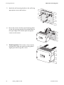
3. Attach the wall mounting bracket to the wall using
appropriate screws and washers.
4. Mount the inverter with the upper fastening plates
on the wall mounting bracket so that both plates on
the upper edge of the bracket pass through the
cutouts on the inverter.
5. Visual inspection: The inverter is only correctly
mounted when both rear panel mounting plates
slightly protrude through the cutouts.
18
WB33_38-IEN101830
Installation Guide
SMA Solar Technology AG
Mounting the Device
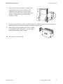
6. Secure the inverter in position by screwing the
supplied M6 contact screw, located on the
underside of the enclosure. Use the contact
washers provided with the toothing against the
enclosure. Tighten the screw with a torque
of approx. 5 Nm.
7. Check to ensure that the inverter is firmly fastened. The wall mounting bracket is designed so
that the inverter tilts backward slightly on a perfectly vertical wall.
8. Attach the air grills provided to the inverter. To help
you identify the sides, "links/left" or "rechts/right" is
printed on the inside of the air grids.
☑ The inverter is now mounted.
Installation Guide
WB33_38-IEN101830
19
Electrical Connection
SMA Solar Technology AG
5 Electrical Connection
5.1 Safety
NOTICE!
Electrostatic discharges can damage the inverter.
Internal components of the inverter can be irreparably damaged by static discharge.
• Before you touch a component inside the inverter, ground yourself by touching
a grounded object.
5.2 Overview of the Connection Area
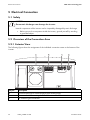
5.2.1 Exterior View
The following figure shows the assignment of the individual connection areas on the bottom of the
inverter.
Object
A
B
C
Description
Enclosure openings for communication (with dummy plugs)
PV connectors for connecting the DC cables
AC socket for grid connection
20
WB33_38-IEN101830
Installation Guide
SMA Solar Technology AG
Electrical Connection
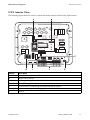
5.2.2 Interior View
The following figure shows the various components and connection areas of the open inverter.
Object
A
B
C
D
E
F
G
Description
Socket and connection area for communication
Jumper slot for fan test
Tab for grounding the cable shield with line-conducted communication
AC socket for grid connection
PV connectors for connecting the small wind turbine system
Enclosure opening with sealing plugs for communication
Varistors
Installation Guide
WB33_38-IEN101830
21
Electrical Connection
SMA Solar Technology AG
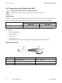
5.3 Connection to the Public Grid (AC)
Connection requirements of the utility operator
Always observe the connection requirements of the utility operator.
Cable Sizing
The cable cross-section should be dimensioned so output losses do not exceed 1 % at nominal power.
Maximum cable lengths relative to the cable cross-section are shown in the following table:
Cable cross-section
4 mm²
Maximum cable length
WB 3300
WB 3800
18.5 m
16 m
The conductor cross-sectional area required in individual cases depends on the following factors,
among others:
• Ambient temperature,
• Routing method,
• UV resistance,
• Conduction losses,
• Valid installation guidelines of the respective country (of the installation location).
Cable Requirements
Object
A
B
C
22
Description
External diameter
Conductor cross-section
Strip insulation
WB33_38-IEN101830
Value
6 mm … 14 mm
4 mm²
8 mm
Installation Guide
SMA Solar Technology AG
Electrical Connection
Load Disconnection Unit
You must install a separate line circuit breaker for each inverter in order to ensure that the inverter
can be securely disconnected under load. The maximum permissible rating is located in
section 11 ”Technical Data” (page 63).
Detailed information and examples for the design of a line circuit breaker can be found in the
Technical Information "Line Circuit Breaker" in the SMA Solar Technology AG download area at
www.SMA.de/en.
DANGER!
Danger to life due to fire.
When more than one inverter is connected to the same line circuit breaker, the protective
function of the line circuit breaker is no longer guaranteed. It can result in a cable fire or
the destruction of the inverter.
• Never connect several inverters to the same line circuit breaker.
• Comply with the maximum permissible fuse protection of the inverter when selecting
the line circuit breaker.
DANGER!
Danger to life due to fire.
When a generator (inverter) and a consumer are connected to the same line circuit
breaker, the protective function of the line circuit breaker is no longer guaranteed. The
current from the inverter and the grid can accumulate to overcurrent, which is not detected
by the line circuit breaker.
• Never connect the consumer between the
inverter and the line circuit breaker without
protection.
• Always protect the consumer separately.
NOTICE!
Damage to the inverter by using screw type fuse elements as a load
disconnection unit.
A screw type fuse element, e.g. D system (Diazed) or D0 system (Neozed) is not
a load disconnection unit, and thus may not be used as a load disconnection unit.
A screw type fuse element is only used as cable protection.
When disconnecting under load using a screw type fuse element, the inverter can be
damaged.
• Use only a load disconnection switch or a line circuit breaker as a load disconnecting
unit.
Installation Guide
WB33_38-IEN101830
23
Electrical Connection
SMA Solar Technology AG
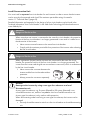
5.3.1 Connecting the Inverter to the Public Grid (AC)
Overview of the AC connection socket
Object
A
B
C
D
E
Description
Protective cap for socket element
Socket element
Threaded sleeve with sealing ring for cable diameters from 10 mm … 14 mm
Sealing ring for cable diameters of 6 mm … 10 mm
Clamping nut
Procedure
1. Check that the grid voltage is within the permissible voltage range.
The exact operating range of the inverter is specified in the operating parameters. The
corresponding document is located in the download area at www.SMA.de/en, in the
"Technical Description" category of the respective inverter.
2. Disconnect the line circuit breaker and secure against re-connection.
3. If necessary, exchange the sealing ring of the threaded sleeve with the sealing ring provided.
– Pull the sealing ring out of the threaded sleeve.
– Insert the smaller sealing ring.
4. Thread the clamping nut (E) over the AC cable.
24
WB33_38-IEN101830
Installation Guide
SMA Solar Technology AG
Electrical Connection
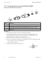
5. Thread the threaded sleeve (C) with the sealing ring over the AC cable.
6. Bend the AC cable. The bend radius must be at
least four times the cable diameter.
7. Shorten the cable.
8. Shorten phase L and neutral conductor N
4 mm to 5 mm.
9. Insert the PE protective conductor (green-yellow)
into the screw terminal with the earth sign on the
socket element and tighten the screw.
The PE protective conductor must be longer than
the connection wires of N and L.
10. Insert the neutral conductor N (blue) in the screw
terminal N on the socket element and tighten the
screw.
11. Insert phase L (brown or black) into the
screw terminal L on the socket element and tighten
the screw.
12. Make sure the wires are securely connected.
13. Push the threaded sleeve (C) onto the socket element (B) until it audibly snaps into place.
Installation Guide
WB33_38-IEN101830
25
Electrical Connection
SMA Solar Technology AG
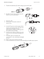
14. Screw the clamping nut (E) tightly onto the threaded sleeve (C). The clamping nut serves to seal
and relieve strain.
☑ The AC connection socket has been screwed together.
15. Close the socket element with the provided protective cap, if it is not immediately connected to
the inverter.
16. Insert the AC connection socket into the AC socket
on the inverter. Remove the protective cap
beforehand as required.
☑ The AC cable is now connected to the inverter.
26
WB33_38-IEN101830
Installation Guide
SMA Solar Technology AG
Electrical Connection
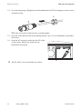
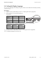
5.4 Setting the Display Language
You can set the language of the display using the switches on the underside of the display assembly
inside the inverter.
Procedure
1. Open the inverter as described in section 7.2 ”Opening the Inverter” (page 44).
2. Set the switches for the required language, as
shown below.
Language
German
English
French
Spanish
Switch S2
B
B
A
A
Switch S1
B
A
B
A
For type WB 3300-IT / 3800-IT inverters, the following switch settings apply:
Language
Italian
English
Switch S2
B
A
Switch S1
A
A
3. Close the inverter as described in section 7.3 ”Closing the Inverter” (page 45).
☑ The display language has now been set.
Installation Guide
WB33_38-IEN101830
27
Electrical Connection
SMA Solar Technology AG
5.5 Connecting the Small Wind Turbine System (DC)
5.5.1 Conditions for the DC Connection
• The connection cables of the small wind turbine system must be equipped with plug connectors.
You will find the necessary PV connector for DC connection in the delivery.
• The following limit values at the DC input of the inverter may not be exceeded:
Maximum input voltage
500 V
Maximum input current
20 A
DANGER!
Risk of lethal electric shock or fire.
The maximum possible input current is limited by the plug connectors used. If the plug
connector is overloaded, an electric arc may occur and there is a fire risk.
• Ensure that the input current does not exceed the maximum flow current of the plug
connectors used.
NOTICE!
Destruction of the inverter by overvoltage.
If the voltage of the small wind turbine system exceeds the maximum input voltage of the
inverter, it can be destroyed by the overvoltage. All warranty claims become void.
• Install overvoltage protection, e.g. Windy Boy Protection Box, between the small
wind turbine system and the inverter.
28
WB33_38-IEN101830
Installation Guide
SMA Solar Technology AG
Electrical Connection
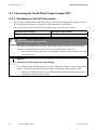
5.5.2 Assembling the PV connector
The connection cables of the small wind turbine system must be equipped with the PV connectors
provided for connecting the inverter.
To assemble the PV connectors, proceed as detailed below. Ensure the plug connectors have the
correct polarity. The PV connectors have the symbols "+" and " − ".
Cable Requirements
• Use a PV1-F cable.
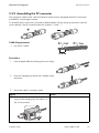
Procedure
1. Insert stripped cable into the plug as far as it will go.
2. Press the clamping clip down until it audibly snaps
into place.
3. Ensure the cable is correctly in place.
Result
☑ If the conductors are visible in the hollow
cavity of the clamping clip, the cable is in
the correct position.
Installation Guide
Action
• Proceed to step 4.
WB33_38-IEN101830
29
Electrical Connection
SMA Solar Technology AG
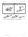
Result
Action
☑ If the conductors are not visible in the
• Loosen the clamping clip using a
hollow cavity, the cable is not in the correct
screwdriver.
position.
• Remove cable and start again from step 1.
4. Push the threaded joint to the thread and screw into place.
☑ The PV connectors are now assembled and can be connected to the inverters, as described in
section 5.5.4 ”Connecting the Small Wind Turbine System (DC)” (page 32).
30
WB33_38-IEN101830
Installation Guide
SMA Solar Technology AG
Electrical Connection
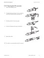
5.5.3 Opening the PV connector
1. Screw the threaded joint off.
2. To release the plug connector, slot a screwdriver
into the side catch mechanism and lever out.
3. Carefully pull the PV connector apart.
4. Loosen the clamping clip using a screwdriver.
5. Remove the cable.
☑ The cable is now removed from the PV connector.
Installation Guide
WB33_38-IEN101830
31
Electrical Connection
SMA Solar Technology AG
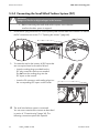
5.5.4 Connecting the Small Wind Turbine System (DC)
DANGER!
Danger to life due to high voltages in the inverter.
• Before connecting the small wind turbine system, ensure that the
small wind turbine system is stopped.
1. Check the DC plug connectors for correct polarity and connect them to the inverter. To release
the DC connectors see section 7.2 ”Opening the Inverter” (page 44).
2. To create the seal on the inverter, all DC inputs that
are not required must be closed as follows:
– Insert the sealing plugs provided into the
DC plug connectors that are not needed.
Do not insert the sealing plugs into the
DC inputs on the inverter.
– Insert the PV connectors with sealing plugs into
the corresponding DC inputs on the inverter.
☑ The small wind turbine system is connected.
You can now commission the inverter as described
in section 6 ”Commissioning” (page 36). The
following connection options are optional.
32
WB33_38-IEN101830
Installation Guide
SMA Solar Technology AG
Electrical Connection
5.6 Communication
The inverter is equipped with a slot for communication interfaces, so that it can communicate using
special data acquisition devices (e.g. Sunny WebBox) or a PC with appropriate software.
Refer to the communication interface manual for a detailed circuit diagram and a description of the
mounting.
5.7 Setting the Grid and Country Parameters
Changing Grid-Relevant and Country Parameters
To change grid-relevant parameters, you need a personal access code - the so-called
SMA Grid Guard Code. The application form for the personal access code is located in
the download area at www.SMA.de/en, in the "Certificate" category for each inverter.
Confirm the changes to these parameters with your utility operator.
A detailed description of the operating parameters for the inverter is available in the download area
at www.SMA.de/en in the category "Technical Description" of the respective inverter.
5.7.1 Setting the Installation Country
Using the "Default" parameter you can set the installation country and/or the grid connection
standard valid for the country via a communication device (e.g. Sunny WebBox) or a PC with
corresponding software (e.g. Sunny Data Control). This, however, is only required if the inverter was
originally ordered for another country. You can see the standard to which the inverter was set upon
delivery from the type label and the supplementary document provided with the factory settings.
Installation Guide
WB33_38-IEN101830
33
Electrical Connection
SMA Solar Technology AG
5.7.2 Setting Off-Grid Operation
To operate the inverter in an off-grid system with Sunny Island, you must set the inverter via the
"Default" parameter to off-grid ("OFF-Grid") operation.
You have several possibilities to set the inverter to off-grid operation:
• Setting via Sunny WebBox
or
• Setting via Sunny Data Control.
DANGER!
Danger to life due to high voltages in the event of outage of the public grid.
If you set the inverter to off-grid operation, it does not fulfill any country-specific standards
and regulations. Therefore, if there is an outage of the public grid, there is a danger of back
feed.
• Never operate the inverter directly on the public grid when set to off-grid operation.
34
WB33_38-IEN101830
Installation Guide
SMA Solar Technology AG
Electrical Connection
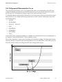
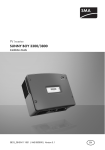
5.8 Polynomial Characteristic Curve
The polynomial characteristic curve is a programmable power curve depending on the DC input
voltage. By adapting the default polynomial characteristic curve to the small wind turbine system
being used, you can optimize the energy output of the small wind turbine system.
To optimally adapt the polynomial characteristic curve of the inverter to the small wind turbine system
being used, you can change the following parameters on the PC with the "Windy Boy Setup Tool"
(www.SMA.de/en):
• Vpv-Start
• UdcWindStart
• Wind_a0 … Wind_a3
• Pmax
• P-Wind-Ramp
• KP-Wind-Reg
• KI-Wind-Reg
• T-Stop
A description of the operating parameters is available in the download area at www.SMA.de/en in
the category "Technical Description" of the respective inverter.
The inverter regulates its output power according to the generator voltage. The following illustration
shows the function of a typical polynomial characteristic curve of a WB 3300 / WB 3800. Here, the
fed-in AC power is shown according to the DC input voltage of the inverter
Installation Guide
WB33_38-IEN101830
35
Commissioning
SMA Solar Technology AG
6 Commissioning
Self test in accordance with DK 5940, Ed. 2.2 for initial commissioning
(applies to Italy only)
The Italian DK 5940 standard prescribes that an inverter can only operate on the public
grid after the disconnection times for overvoltage, undervoltage, minimum frequency and
maximum frequency have been checked.
Start the self-test as described in the section 6.2 ”Self-Test in accordance with DK 5940,
Ed. 2.2 (Applies to Italy Only)” (page 37). The test takes approx. 8 minutes.
6.1 Commissioning the Inverter
1. Check the following requirements before commissioning:
– Correct mounting and correct connection of the inverter.
– Correct layout of the line circuit breaker.
– Correct grounding of the small wind turbine system in accordance with the instructions of the
manufacturer.
– The rectifier and overvoltage protection (e.g. Windy Boy Protection Box) are installed
between the small wind turbine system and the inverter.
– Unnecessary DC inputs are closed with the corresponding DC connectors and sealing plugs.
2. Switch on the line circuit breaker.
3. Commission the small wind turbine system in accordance with the instructions of the
manufacturer.
☑ If green LED glows: commissioning has been successful.
or
☑ If green LED flashes: network connection conditions have not yet been reached. Wait until
the green LED lights up.
or
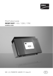
☑ The red or yellow LED is glowing or flashing: there is an error. Proceed to step 3.
Object
A
B
C
Description
Green LED: Operation
Red LED: Ground fault or varistor
defective
Yellow LED: Disturbance
4. Read section 9 ”Troubleshooting” (page 51) and if necessary eliminate the fault or disturbance.
36
WB33_38-IEN101830
Installation Guide
SMA Solar Technology AG
Commissioning
6.2 Self-Test in accordance with DK 5940, Ed. 2.2
(Applies to Italy Only)
6.2.1 Starting the Self-Test by Tapping
You can start testing the disconnection times by tapping on the enclosure lid. A prerequisite here is
that the country configuration of the inverter has been set to Italy (IT/DK5940) or "trimmed". Proceed
as follows for checking the disconnection times:
1. Connect the small wind turbine system with the inverter. The inverter can only initialize if the
small wind turbine system produces enough power. It is therefore not possible to test the
disconnection times at night.
2. Connect the inverter on the AC side. For this, you have to create the AC connection (AC plug
or direct connection) and/or switch on the line circuit breaker of the grid cable (fuse or
automatic circuit breaker).
3. The inverter is now in the initialization phase, i.e. all 3 LEDs are glowing at the same time.
Start the self-test immediately after all 3 LEDs have gone out by tapping on the display of the
inverter.
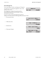
4. The question of whether you would like to start the
test sequence appears in the display. Tap on the
display again within 30 seconds to confirm the
question.
Once you have started the test sequence, the inverter checks the disconnection times for overvoltage,
undervoltage, maximum frequency and minimum frequency one after the other. During the tests, the
inverter shows the values in the display which are described in section 6.2.2 ”Completion of the SelfTest” (page 37).
6.2.2 Completion of the Self-Test
Note the values which are displayed during the self-test. These values must be entered into a test
protocol. The test results of the individual tests are displayed 3 times, one after the other.
The respective display message is displayed for 10 seconds.
The self-test changes the upper and lower disconnection thresholds for each protective function on a
linear basis with a modification of 0.05 Hz/s and 0.05 Vn/s for the frequency and voltage
monitoring. As soon as the actual measurement value is outside the permitted range (altered
disconnection threshold), the inverter disconnects itself from the grid. In this way, the inverter
determines the reaction time and checks itself.
Installation Guide
WB33_38-IEN101830
37
Commissioning
SMA Solar Technology AG
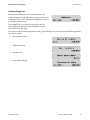
Overvoltage Test
The inverter begins with the overvoltage test. During the
test sequence, the voltage limit applied is shown in the
display of the inverter.
The voltage limit is reduced successively until the
disconnection threshold is reached and the inverter
disconnects from the grid.
Once the inverter has disconnected from the grid, the
display successively shows the following values one after the other:
• Disconnection value,
• Calibration value,
• Reaction time,
• Present grid voltage.
38
WB33_38-IEN101830
Installation Guide
SMA Solar Technology AG
Commissioning
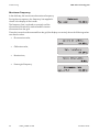
Undervoltage Test
After the overvoltage test, the inverter performs the
undervoltage test. During the test sequence, the current
calibration value of the voltage limit applied is shown in
the display of the inverter.
The voltage limit is increased successively until the
disconnection threshold is reached and the inverter
disconnects from the grid.
Once the inverter has disconnected from the grid, the display successively shows the following values
one after the other:
• Disconnection value,
• Calibration value,
• Reaction time,
• Present grid voltage.
Installation Guide
WB33_38-IEN101830
39
Commissioning
SMA Solar Technology AG
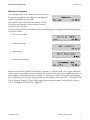
Maximum Frequency
In the third step, the inverter tests the maximum frequency.
During the test sequence, the frequency limit applied is
shown in the display of the inverter.
The frequency limit is reduced successively until the
disconnection threshold is reached and the inverter
disconnects from the grid.
Once the inverter has disconnected from the grid, the display successively shows the following values
one after the other:
• Disconnection value,
• Calibration value,
• Reaction time,
• Present grid frequency.
40
WB33_38-IEN101830
Installation Guide
SMA Solar Technology AG
Commissioning
Minimum Frequency
In the last step, the inverter tests the minimum frequency.
During the test sequence, the frequency limit applied is
shown in the display of the inverter.
The frequency limit is increased successively until the
disconnection threshold is reached and the inverter
disconnects from the grid.
Once the inverter has disconnected from the grid, the display successively shows the following values
one after the other:
• Disconnection value,
• Calibration value,
• Reaction time,
• Present grid frequency.
When the inverter has carried out the 4 tests, it switches to "Turbine" mode. The original calibration
values are then re-set and the inverter automatically connects to the grid. If you would like to carry out
the test again, you must disconnect the inverter, i.e. disconnect it on the AC and DC sides and then
later re-activate it. You can then restart the self-test as described in the section 6.2.1 ”Starting the SelfTest by Tapping” (page 37). The inverter begins the test sequence again, as described in section
6.2.2 ”Completion of the Self-Test” (page 37).
Installation Guide
WB33_38-IEN101830
41
Commissioning
SMA Solar Technology AG
6.3 Operating Conditions of the Inverter
Startup Procedure
If the inverter has enough voltage and power, the startup process is displayed by means of
simultaneous lighting of the three LEDs on the inverter.
As soon as the DC input voltage reaches the value defined in the parameter "Vpv-Start", the inverter
starts a number of self-tests and measurement processes and synchronizes with the grid. This operating
mode is indicated by the green LED flashing on the inverter.
When the tests are successfully completed and the DC input voltage is above "Vpv-Start" for the time
configured in "T-Start," the inverter connects to the grid and the green LED lights up. The inverter then
switches to characteristic curve operation, and regulates the input current according to the generator
voltage.
Characteristic Curve Operation
After the startup procedure, the inverter switches to characteristic curve operation and regulates the
input current according to the generator voltage.
The inverter then begins to put a load on the small wind turbine system, takes power from the small
wind turbine system according to the present input voltage and then feeds it into the grid. The
maximum output corresponds to the maximum AC power of the inverter. However, it can be reduced
using the "Pmax" parameter.
Shutdown
If the wind strength is so low that the DC input voltage falls below an internally calculated value, then
the inverter stops feeding power into the mains grid for the period defined in "T-Stop". When the
DC input voltage increases again, the inverter switches back to characteristic curve operation.
If the DC input voltage remains below an internally calculated value for the time set in "T-Stop", the
inverter will switch off.
If the DC input voltage is no longer sufficient to supply the on-board electronics with power, the
inverter deactivates immediately.
42
WB33_38-IEN101830
Installation Guide
SMA Solar Technology AG
Opening and Closing
7 Opening and Closing
7.1 Safety
DANGER!
Electric shock due to high voltages in the inverter. This can result in death or
serious burns.
Observe the following before opening the inverter:
• Ensure the AC side is not live.
• Ensure the DC side is not live.
NOTICE!
Electrostatic discharges can damage the inverter.
Internal components of the inverter can be irreparably damaged by electrostatic
discharge.
• Ground yourself before touching a component inside the inverter.
Installation Guide
WB33_38-IEN101830
43
Opening and Closing
SMA Solar Technology AG
7.2 Opening the Inverter
1. Disconnect the line circuit breaker and secure against re-connection.
2. Stop the small wind turbine system and make sure that it will not restart.
3. Using a current probe, ensure that there is no
current to all DC cables.
☑ If there is a current present, check the
installation.
4. Unlock all DC connectors using a screwdriver:
– Insert a screwdriver into one of the side slits (1).
– Lever the screwdriver upward (2) and pull out
the plug connector (3).
5. Ensure that there is no voltage at the DC plugs at the inverter.
☑ If there is a voltage present, check the installation.
6. Pull out the AC plug.
7. Check whether all LEDs and the display have gone out.
44
WB33_38-IEN101830
Installation Guide
SMA Solar Technology AG
Opening and Closing
DANGER!
Danger to life due to high voltages in the inverter.
The capacitors in the inverter require 15 minutes to discharge.
• Wait 15 minutes before opening the inverter.
8. Loosen the screws of the enclosure lid.
9. Carefully remove the lid forward.
☑ The inverter is now open and is not live.
7.3 Closing the Inverter
1. Secure the lid with the 4 screws and the lock
washers with the toothing facing toward the lid. The
screws must be tightened with approximately 6 Nm
torque to ensure the sealing of the enclosure and
the grounding of the lid.
DANGER!
Danger to life due to live lid.
The grounding of the lid is ensured by the toothed lock washers.
• Fasten the lock washers for all 6 screws with the toothing facing toward the lid.
2. Check the PV connector for correct polarity and connect it.
To release the plug connectors see section 7.2 ”Opening the Inverter” (page 44).
3. Close all unnecessary DC inputs as described in section 5.5.4 ”Connecting the Small Wind
Turbine System (DC)” (page 32) to seal the inverter.
Installation Guide
WB33_38-IEN101830
45
Opening and Closing
SMA Solar Technology AG
4. Connect the AC plug.
5. Switch on the line circuit breaker.
6. Check whether the inverter's display and
LED display indicate normal operating mode (see
section 6 ”Commissioning” (page 36)).
☑ The inverter is now closed and in operation.
46
WB33_38-IEN101830
Installation Guide
SMA Solar Technology AG
Maintenance and Cleaning
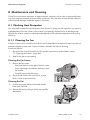
8 Maintenance and Cleaning
Check for correct inverter operation at regular intervals. Impurities such as dust or airborne blossoms
can cause heat concentration that can lead to yield losses. Also check the inverter and the cables for
visible external damage. Undertake repairs if necessary.
8.1 Checking Heat Dissipation
You only need to check the heat dissipation of the inverter if, during a visual inspection, you notice a
marked build-up in the fan screen or the inverter is increasingly observed to be in derating mode.
Whether the inverter switches to derating mode depends on the ambient temperature and cooling
efficiency.
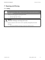
8.1.1 Cleaning the Fan
If the fan screen is only covered in loose dust it can be cleaned with a vacuum cleaner. If you do not
achieve satisfactory results with a vacuum cleaner, dismantle the fans for cleaning.
Proceed as follows:
1. Disconnect the inverter from both the DC and AC connections, as described in section
7.2 ”Opening the Inverter” (page 44).
2. Wait for the fan to stop rotating.
Cleaning the Fan Screen
3. Remove the fan screen:
– Press both latches on the right of the fan screen
to the right using a screwdriver and loosen from
the bracket.
– Carefully remove the fan screen.
4. Clean the fan screen with a soft brush, a paint
brush, a cloth or pressurized air.
Cleaning the Fan
5. Push the two upper latches backward and the
lower latch forward.
6. Remove the fan by pulling it slowly and carefully
downward.
Installation Guide
WB33_38-IEN101830
47
Maintenance and Cleaning
SMA Solar Technology AG
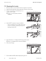
7. Unlock and unplug the fan plug inside the inverter.
The fan cables are long enough that you can lift the fan far enough out to disconnect the internal
plug connector in the inverter.
8. Remove the fan.
9. Clean the fan with a soft brush, a paint brush, or a damp cloth.
NOTICE!
Damage to the fan through the use of pressurized air.
• Do not use pressurized air to clean the fan. This can damage the fan.
10. After cleaning, assemble everything in reverse order.
11. Check the functioning of the fan as described in the following section.
8.1.2 Checking the Fan
You can check that the fan is working in 2 ways:
• Set the "Fan-Test" parameter to "1" in the installer mode using Sunny Data Control or
Sunny WebBox.
or
• Plug the provided jumper into the sequential control system board.
Setting Parameters
1. Request the installer password from the SMA Serviceline (contact: see page 70).
2. Set the "Fan‑Test" parameter to "1" in the installer mode.
3. Check the air-flow of the fan.
The inverter sucks air in from underneath and then blows it back out on the upper left side. Listen
for any unusual noise that could indicate incorrect installation or that the fan is faulty.
4. After checking the fan, set the "Fan‑Test" parameter back to "0".
☑ You have finished checking the fan.
48
WB33_38-IEN101830
Installation Guide
SMA Solar Technology AG
Maintenance and Cleaning
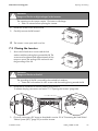
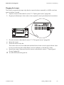
Plugging the Jumper
The inverter recognizes the jumper only after the system has been restarted (i.e. all LEDs must have
gone out before a restart).
1. Open the inverter as described in section 7.2 ”Opening the Inverter” (page 44).
2. Plug the provided jumper in the socket on the sequential control system board as shown below.
3. Close the inverter as described in section 7.3 ”Closing the Inverter” (page 45).
4. Restart the inverter.
5. Check the air-flow of the fan.
The inverter sucks air in from underneath and then blows it back out on the upper left side. Listen
for any unusual noise that could indicate incorrect installation or that the fan is faulty.
6. Remove the jumper. Open and close the inverter as described in section 7 ”Opening and
Closing” (page 43).
☑ You have finished checking the fan.
Installation Guide
WB33_38-IEN101830
49
Maintenance and Cleaning
SMA Solar Technology AG
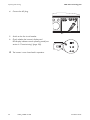
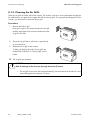
8.1.3 Cleaning the Air Grills
There are air grills on either side of the inverter. The inverter sucks air in from underneath through the
fan and blows it out again on the upper left side via the air grills. For optimal heat dissipation of the
inverter, you only have to clean the left air grill.
Procedure
1. Remove the left air grill.
Insert your finger in the space between the air grill
and the upper part of the enclosure and remove the
air grill to the side.
2. Clean the air grill with a soft brush, a paint brush,
or pressurized air.
3. Re-attach the air grill to the inverter.
To help you identify the sides, the air grills are
marked with "links/left" or "rechts/right" on the
inside.
☑ The air grills are cleaned.
NOTICE!
Risk of damage to the inverter through intrusion of insects.
• The air grills must not be removed permanently, because otherwise the device is not
protected against the entrance of insects.
50
WB33_38-IEN101830
Installation Guide
SMA Solar Technology AG
Troubleshooting
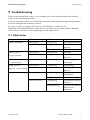
9 Troubleshooting
If the inverter displays blink codes or error messages other than those described in the following
section, contact the SMA Serviceline.
In the user manual provided, you will also find a description of the display messages during operation,
the status messages and measuring channels.
Do not try to carry out repairs other than those described here. Instead, use the
SMA Solar Technology AG 24-hour replacement service (the inverter will be ready for dispatch
within 24 hours and sent to a forwarding agency) and repair service.
9.1 Blink Codes
Green
Glows continuously
Red
Is not glowing
Glows continuously
Yellow
Is not glowing
Is not glowing
(3 x per second)
Is not glowing
Glows continuously
Glows continuously
Is not glowing
Is not glowing
Flashes slowly
Is not glowing
Is not glowing
Flashes quickly
(1 x per second)
Briefly goes out
Is not glowing
(approx. 1 x per second) Glows continuously
Is not glowing
Is not glowing
Is not glowing
Is not glowing
Is not glowing
Glows continuously
Is not glowing
Is not glowing
Glowing/flashing
Installation Guide
Status
OK (feeding operation)
Ground fault or varistor
defective
OK (initialization)
OK (stop)
Ground fault or varistor
defective
OK (waiting, grid
monitoring)
OK (derating)
Ground fault or varistor
defective
OK (night-time
deactivation)
Disturbance
Ground fault or varistor
defective
Ground fault or varistor
defective and
disturbance
WB33_38-IEN101830
51
Troubleshooting
SMA Solar Technology AG
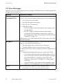
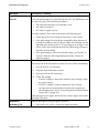
9.2 Error Messages
When en error occurs, the inverter generates a message, which depends on the operating mode and
the type of the detected error.
Message
!PV-Overvoltage!
Description / Remedy
DC overvoltage!
!DISCONNECT DC!
Disconnect the small wind turbine system from the inverter immediately.
1. Turn off the line circuit breaker.
2. Stop the small wind turbine system.
3. Disconnect the PV connectors.
4. Check DC voltage:
– If the DC voltage is above the maximum input voltage, check
the plant design.
– If the DC voltage is under the maximum input voltage,
reconnect the small wind turbine system to the inverter as
described in section 5.5.4 ”Connecting the Small Wind Turbine
System (DC)” (page 32).
ACVtgRPro
If the message occurs again, disconnect the inverter again and contact
the SMA Serviceline.
The 10-minute-average grid voltage is no longer within the permissible
range. This can have the following causes:
• The grid voltage at the connection point is too high.
• The grid impedance at the connection point is too high.
The inverter disconnects to assure compliance with the voltage quality of
the grid.
• Check the grid voltage at the connection point of the inverter:
– If, due to the local grid conditions, the grid voltage is 253 V or
more, ask the utility operator whether the voltage at the feed-in
point can be adjusted, or whether it would agree to an
alteration of the limit value "ACVtgRPro" for voltage quality
monitoring.
Bfr-Srr
– If the grid voltage is continually within the acceptable range
and this error is still displayed, contact the SMA Serviceline.
Internal measurement comparison fault or hardware defect.
• If this fault occurs often, contact the SMA Serviceline.
52
WB33_38-IEN101830
Installation Guide
SMA Solar Technology AG
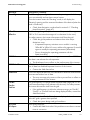
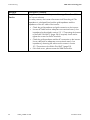
Message
Derating
Troubleshooting
Description / Remedy
The "Derating" operating mode is a normal operating mode which may
occur occasionally and can have several causes.
Once the inverter enters the "Derating" mode, it will display the
"Derating" warning until the next total shutdown of the device (when the
wind is insufficient).
dZac-Bfr
dZac-Srr
• Check heat dissipation, as described in section 8.1 ”Checking
Heat Dissipation” (page 47).
Sudden changes in grid impedance exceed the permissible range
("Bfr" or "Srr" are internal messages of no relevance for the user).
For safety reasons, the inverter disconnects itself from the grid.
• Check the grid impedance and observe how often major
deviations occur.
– If repeated frequency variations occur and this is causing
"dZac-Bfr" or "dZac-Srr" errors, ask the utility operator if it would
agree to modify the operating parameters (dZac-Max).
EEPROM
– Discuss changing the operating parameter with the
SMA Serviceline.
Transition disturbance while data is being written or read from EEPROM.
The data is not relevant for safe operation.
EEPROM dBh
• The disturbance has no effect on the performance of the inverter.
EEPROM data is defective, the inverter has switched itself off because the
loss of data has disabled important functions of the inverter.
EeRestore
• Contact the SMA Serviceline.
One of the duplicate data sets in the EEPROM is defective and has been
reconstructed without loss of data.
Fac-Bfr
• The error message only serves to inform you and has no effect on
the performance of the inverter.
The grid frequency is no longer within the permissible range ("Bfr" or "Srr"
is an internal message of no relevance for the user). For safety reasons,
the inverter disconnects itself from the grid.
Fac-Srr
FacFast
Imax
K1-Close
K1-Open
Installation Guide
• If the grid frequency is within the tolerance range, yet "Fac-Bfr,"
"Fac-Srr", or "FacFast" faults are being displayed often, contact the
SMA Serviceline.
Overcurrent on the AC side. This indicator is displayed when the current
at the AC grid is greater than specified.
• Check the system design and grid conditions.
Fault during relay test.
• Contact the SMA Serviceline if this problem occurs often or several
times in succession.
WB33_38-IEN101830
53
Troubleshooting
SMA Solar Technology AG
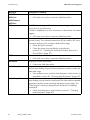
Message
MSD-Fac
Description / Remedy
Internal measurement comparison fault or hardware defect.
MSD-Vac
• If this fault occurs often, contact the SMA Serviceline.
MSD-Timeout
MSD-Zac
Offset
The "Offset" operating condition is a normal operating condition that
occurs prior to grid monitoring.
If "offset" is displayed as an error, then there is a disturbance in the data
logging.
• If this fault occurs often, contact the SMA Serviceline.
The electrical insulation between the small wind turbine system and
ground is faulty. The resistance between the DC plus and/or DC minus
connection and ground is outside the defined limit range.
Riso
• Check the system insulation.
ROM
• Check the system for ground faults as described in
section 9.3.1 ”Checking the Small Wind Turbine System for a
Ground Fault” (page 57).
The inverter's firmware is faulty.
Shutdown
• If this fault occurs often, contact the SMA Serviceline.
Temporary inverter disturbance.
Trafo-Temp-F
Trafo-Temp-W
• Contact the SMA Serviceline.
Temperatures in the transformer have exceeded the acceptable limit. The
inverter stops feeding the grid until the temperature reverts to within the
admissible range.
• If this problem recurs, check the heat dissipation of the inverter, as
described in section 8.1 ”Checking Heat Dissipation” (page 47).
If the transformer reaches an unacceptably high temperature, the inverter
stops feeding-in the grid until the transformer has reached an acceptable
temperature and the system can begin feeding-in the grid again. The
"Trafo-Temp-W" warning is displayed until the device is completely
switched off.
• Check heat dissipation, as described in section 8.1 ”Checking
Heat Dissipation” (page 47).
54
WB33_38-IEN101830
Installation Guide
SMA Solar Technology AG
Message
Vac-Bfr
Vac-Srr
Troubleshooting
Description / Remedy
The grid voltage is no longer within the permissible range ("Bfr" or "Srr"
is an internal message of no relevance for the user). This disturbance can
be caused by any of the following conditions:
• Grid disconnected (line circuit breaker, fuse),
• AC cable is broken or
• AC cable is highly resistive
For safety reasons, the inverter disconnects itself from the grid.
• Check the grid current and grid connection on the inverter.
• If the grid voltage lies outside the acceptable range because of
local grid conditions, ask the utility provider if the voltage can be
adjusted at the feed-in point or if it would agree to changes in the
values of the monitored operational limits (operating parameters:
Vac-Min and Vac-Max).
Vpv-Max
• If the grid voltage is within the tolerable range, yet "Vac-Bfr," or
"Vac-Srr" faults are still being displayed, please contact the
SMA Serviceline.
Overvoltage at DC input. The inverter may be damaged.
Disconnect the small wind turbine system from the inverter immediately.
1. Turn off the line circuit breaker.
2. Stop the small wind turbine system.
3. Disconnect all the DC connectors.
4. Check DC voltage:
– If the DC voltage is above the maximum input voltage, check
the system design.
– If the DC voltage is under the maximum input voltage,
reconnect the small wind turbine system to the inverter as
described in section 5.5.4 ”Connecting the Small Wind Turbine
System (DC)” (page 32).
Watchdog
Watchdog Srr
Installation Guide
If the message occurs again, disconnect the inverter again and contact
the SMA Serviceline.
Internal disturbance during program operation.
• If this fault occurs often, contact the SMA Serviceline.
WB33_38-IEN101830
55
Troubleshooting
Message
Zac-Bfr
Zac-Srr
SMA Solar Technology AG
Description / Remedy
The grid impedance has left the permissible range. The suffixes "Bfr" und
"Srr" are not relevant.
For safety reasons, the inverter disconnects itself from the grid. The
impedance is calculated from both the grid impedance and the
impedance of the AC cable of the inverter.
• Check the grid impedance and grid connection on the inverter.
• Use an AC cable with an adequate cross-sectional area (= low
impedance) as described in section 5.3.1 ”Connecting the Inverter
to the Public Grid (AC)” (page 24). If required, check and retighten the screws on the AC terminals.
• Check the grid impedance and the AC connection on the inverter.
Use a cable with an adequate cross-sectional area (= low
impedance), observing the advice on this matter in section
5.3 ”Connection to the Public Grid (AC)” (page 22).
• If this fault recurs, please contact the SMA Serviceline.
56
WB33_38-IEN101830
Installation Guide
SMA Solar Technology AG
Troubleshooting
9.3 Red LED is Glowing Continuously
If the red LED of the status display is continuously on during operation, there is either a ground fault
in the system or at least one of the varistors for the overvoltage protection is defective.
In intentionally grounded systems, the red LED has been lit up since the commissioning of the inverter.
However, this has no impact on the functioning of the inverter. Before you check the small wind turbine
system for a ground fault, make sure an intentional connection to the ground has been carried out.
With intentionally grounded small wind turbine systems, check occasionally that the varistors inside
the inverter function correctly, since a fault with the varistors can no longer be displayed.
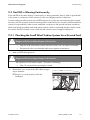
9.3.1 Checking the Small Wind Turbine System for a Ground Fault
DANGER!
Danger to life due to high voltages in the inverter.
• Stop the small wind turbine system and ensure that it can not restart accidentally.
• Disconnect the line circuit breaker and secure against re-connection.
1. Wait until LEDs have gone out.
DANGER!
Danger to life due to high voltages in the inverter.
The capacitors in the inverter require 15 minutes to discharge.
• Wait 15 minutes before opening the inverter.
2. Ensure there is no current at any DC cables using a
clip-on ammeter.
☑ If there is a current present, check the
installation.
Installation Guide
WB33_38-IEN101830
57
Troubleshooting
SMA Solar Technology AG
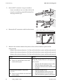
3. Unlock all DC connectors using a screwdriver:
– Insert a screwdriver into one of the side slits (1).
– Lever the screwdriver upward (2) and pull out
the plug connector (3).
4. Remove the AC connection socket from the inverter.
5. Measure the resistance between the phases of the small wind turbine system and the
earth potential:
– Measure the resistance between L1 of the small wind turbine system and the earth potential.
– Measure the resistance between L2 of the small wind turbine system and the earth potential.
– Measure the resistance between L3 of the small wind turbine system and the earth potential.
Result
The measured resistance is almost infinite.
☑ There is no ground fault in the small
wind turbine system.
The measured resistance is very small
(< 10 Ω ).
☑ There is a ground fault in the small wind
turbine system.
58
WB33_38-IEN101830
Action
There is probably a ground fault in the
Windy Boy Protection Box or in the supply lines
to the inverter.
• Separate the Windy Boy Protection Box
from the inverter and measure the
resistance of all connections and the earth
potential.
• Have the installer of the
small wind turbine system correct the
ground fault before reconnecting the
small wind turbine system to the inverter.
Installation Guide
SMA Solar Technology AG
Troubleshooting
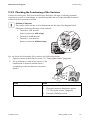
9.3.2 Checking the Functioning of the Varistors
Varistors are wear parts. Their functional efficiency diminishes with age or following repeated
responses as a result of overvoltages. It is therefore possible that one of the thermally monitored
varistors has lost its protective function.
Position of Varistors
The position of the varistors is to be determined with the help of the diagram below.
Observe the following allocation of the terminals:
• Terminal A: outer terminal
(varistor connection with crimp)
• Terminal B: middle terminal
• Terminal C: outer terminal
(varistor connection without crimp)
You can check the functionality of the varistors in the following manner:
1. Open the inverter as described in section 7.2 ”Opening the Inverter” (page 44).
2. Use a multimeter to check all the varistors in the
installed state to ascertain whether there is
a conducting connection between connectors
B and C.
Result
There is a conducting connection.
Action
There is probably a different fault in the inverter.
1. Close the inverter as described in section
7.3 ”Closing the Inverter” (page 45).
2. Contact the SMA Serviceline.
Installation Guide
WB33_38-IEN101830
59
Troubleshooting
SMA Solar Technology AG
Result
There is no conducting connection.
Action
The respective varistor is defective and must be
replaced.
Varistor failure is generally due to influences which
affect all varistors similarly (temperature, age, induced
overvoltage). SMA Solar Technology AG
recommends that you replace both varistors.
The varistors are specially manufactured for use in the
inverter and are not commercially available. You must
order replacement varistors directly from
SMA Solar Technology AG
(see section 13 ”Contact” (page 70)).
• For the replacement of the varistors, proceed to
step 3.
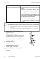
NOTICE!
Overvoltage due to faulty varistors. Destruction of the inverter by overvoltage.
• Procure replacement varistors as soon as possible and replace the defective ones
immediately.
• For systems with a high risk of overvoltage, do not operate inverters using faulty
varistors or no varistors at all.
3. Insert an insertion tool into the openings of the
terminal contacts (1).
☑ This releases the terminals.
If you did not receive an extractor tool together with
the replacement varistors for the servicing of the
terminals, contact SMA Solar Technology AG. As
an alternative, the individual terminal contacts can
be operated using a 3.5 mm wide screwdriver.
4. Remove the varistor (2).
5. Insert new varistor (3).
The pole with the small loop (crimp) must be fitted
to terminal A when remounting (3).
6. Close the inverter as described in
section 7.3 ”Closing the Inverter” (page 45).
☑ The check and replacement of the varistors is
completed.
60
WB33_38-IEN101830
Installation Guide
SMA Solar Technology AG
Decommissioning
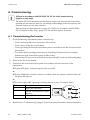
10 Decommissioning
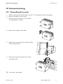
10.1 Dismantling the Inverter
1. Open the enclosure lid as described in section 7.2 ”Opening the Inverter” (page 44).
2. Remove all cables from the inverter.
3. Close the inverter with the 4 screws and the
corresponding lock washers.
4. Remove the air grills on both sides.
5. Remove the screw between the product and the
wall mounting bracket.
6. Remove the inverter upwards from the wall
mounting bracket.
☑ The inverter is dismantled.
Installation Guide
WB33_38-IEN101830
61
Decommissioning
SMA Solar Technology AG
10.2 Packing the Inverter
If possible, always pack the inverter in its original packaging. If it is no longer available, you can also
use an equivalent carton. The box must be capable of being closed completely and made to support
both the weight and the size of the inverter.
10.3 Storing the Inverter
Store the inverter in a dry place where ambient temperatures are always between − 25 °C and
+60 °C.
10.4 Disposing of the Inverter
Dispose of the inverter at the end of its service life in accordance with the disposal regulations for
electronic waste which apply at the installation site at that time. Alternatively, send it back to
SMA Solar Technology AG with shipping paid by sender, and labeled "ZUR ENTSORGUNG"
("FOR DISPOSAL") (see section 13 ”Contact” (page 70)).
62
WB33_38-IEN101830
Installation Guide
SMA Solar Technology AG
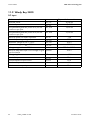
Technical Data
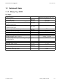
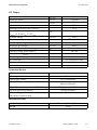
11 Technical Data
11.1 Windy Boy 3300
DC Input
Turbine control
Nominal power
Maximum power
Recommended generator power at 2,500 fullload hours per year
Recommended generator power at 5,000 fullload hours per year
Minimum power for feed-in operation
Nominal operating voltage
Maximum voltage at UAC = 230 V
Minimum voltage at UAC = 230 V
Voltage range at UAC = 230 V
Minimum adjustable open circuit voltage for grid
synchronization
Voltage ripple
Nominal input current
Overall maximum input current
Number of inputs
Maximum current per input
Installation Guide
PDC, nom
PDC, max
PDC, 2500
Polynomial characteristic curve
3,500 W
3,820 W
3,100 W
PDC, 5000
2,800 W
PDC, min
UDC, nom
UDC, max
UDC, min
7W
200 V
500 V
200 V
200 V … 500 V
200 V
Vpv-Start
UPP
IDC, nom
IDC, max
< 10 %
17.5 A
20 A
3
20 A
WB33_38-IEN101830
63
Technical Data
SMA Solar Technology AG
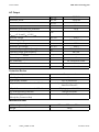
AC Output
Nominal power
Maximum power
Nominal current
Maximum output current
Maximum permissible fuse protection
Harmonic distortion of grid current at
KUgrid < 2 % and PAC > 0.5 Pnom
Nominal voltage
Grid voltage range
Minimum grid voltage
Maximum grid voltage
Nominal frequency (self-adjusting)
Operating range, grid frequency
Power factor at PACnom
Overvoltage category
AC connection
Maximum cable diameter
Maximum wire cross-section
PAC, nom
PAC, max
IAC, nom
IAC max
KIAC
UAC, nom
UAC, min
UAC, max
fAC
cos ϕ
3,300 W
3,600 W
14.5 A
18 A
25 A
<3%
230 V
220 V … 240 V
180 V
260 V
50 Hz / 60 Hz
±4.5 Hz
1
III
AC connection socket
14 mm
4 mm²
Protective Device
AC short circuit protection
Islanding detection
Galvanically isolated
All-pole disconnection unit on the AC side
All-pole disconnection unit on the DC side
DC reverse-polarity protection
DC overvoltage protection
(Windy Boy Protection Box)
Current control
Yes
Yes, LF transformer
Independent disconnection device
SMA Grid Guard 2
DC plug system SUNCLIX
Short-circuit diode
Optional
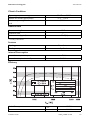
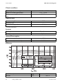
Mechanical Data
Width x height x depth
Weight
64
WB33_38-IEN101830
450 mm x 352 mm x 236 mm
38 kg
Installation Guide
SMA Solar Technology AG
Technical Data
Climatic Conditions
Operating temperature range
Relative air humidity (permissible)
Maximum operating altitude above mean sea
level
− 25 °C … +60 °C
0 % … 100 %
2,000 m
General Data
Protection rating *
Protection class
Noise emission (typical)
IP65
I
≤ 33 dB(A)
* according to IEC 60529
Features
Topology
Cooling concept
LF transformer
OptiCool
Internal Consumption
Internal consumption in operation
Internal consumption in standby
<7W
0.25 W
Efficiency
Peak efficiency
Euro-eta
Installation Guide
η max.
η euro
95.2 %
94.4 %
WB33_38-IEN101830
65
Technical Data
SMA Solar Technology AG
11.2 Windy Boy 3800
DC Input
Turbine control
Nominal power
Maximum power
Recommended generator power at 2,500 fullload hours per year
Recommended generator power at 5,000 fullload hours per year
Minimum power for feed-in operation
Nominal operating voltage
Maximum voltage at UAC = 230 V
Minimum voltage at UAC = 230 V
Voltage range at UAC = 230 V
Minimum adjustable open circuit voltage for grid
synchronization
Voltage ripple
Nominal input current
Overall maximum input current
Number of inputs
Maximum current per input
66
WB33_38-IEN101830
PDC, nom
PDC, max
PDC, 2500
Polynomial characteristic curve
4,040 W
4,040 W
3,600 W
PDC, 5000
3,300 W
PDC, min
UDC, nom
UDC, max
UDC, min
7W
200 V
500 V
200 V
200 V … 500 V
200 V
VpvStart
UPP
IDC, nom
IDC, max
< 10 %
20 A
20 A
3
20 A
Installation Guide
SMA Solar Technology AG
Technical Data
AC Output
Nominal power
Maximum power
Nominal current
Maximum output current
Maximum permissible fuse protection
Harmonic distortion of grid current at
KUgrid < 2 % and PAC > 0.5 Pnom
Nominal voltage
Grid voltage range
Minimum grid voltage
Maximum grid voltage
Nominal frequency (self-adjusting)
Operating range, grid frequency
Power factor at PACnom
Overvoltage category
AC connection
Maximum cable diameter
Maximum wire cross-section
PAC, nom
PAC, max
IAC, nom
IAC, max
KIAC
UAC, nom
UAC, min
UAC, max
fAC
cos ϕ
3,800 W
3,800 W
16.5 A
18 A
25 A
<3%
230 V
220 V … 240 V
180 V
260 V
50 Hz / 60 Hz
±4.5 Hz
1
III
AC connection socket
14 mm
4 mm²
Protective Device
AC short circuit protection
Islanding detection
Galvanically isolated
All-pole disconnection unit on the AC side
All-pole disconnection unit on the DC side
DC reverse-polarity protection
DC overvoltage protection
(Windy Boy Protection Box)
Current control
Yes
Yes, LF transformer
Independent disconnection device
SMA Grid Guard 2
DC plug system SUNCLIX
Short-circuit diode
Optional
Mechanical Data
Width x height x depth
Weight
Installation Guide
450 mm x 352 mm x 236 mm
38 kg
WB33_38-IEN101830
67
Technical Data
SMA Solar Technology AG
Climatic conditions
Operating temperature range
Relative air humidity (permissible)
Maximum operating altitude above mean sea
level
− 25 °C … +60 °C
0 % … 100 %
2,000 m
General Data
Protection rating *
Protection class
Noise emission (typical)
IP65
I
≤ 33 dB(A)
* according to IEC 60529
Features
Topology
Cooling concept
LF transformer
OptiCool
Internal Consumption
Internal consumption in operation
Internal consumption in standby
<7W
0.25 W
Efficiency
Peak efficiency
Euro-eta
68
WB33_38-IEN101830
η max.
η euro
95.6 %
94.7 %
Installation Guide
SMA Solar Technology AG
Accessories
12 Accessories
You will find the corresponding accessories and replacement parts for your inverter in the following
overview. If required, you can order these from SMA Solar Technology AG or your dealer.
Designation
Windy Boy Protection Box
Air grills
Replacement varistors
Insertion tool for replacing
the varistors
RS485 upgrade kit
Bluetooth® Wireless
Technology upgrade kit
SUNCLIX PV connector
Installation Guide
Brief description
Rectifiers and overvoltage protection for
small wind turbine systems with Windy Boy
Air grill set "right and left" as spare part
Set of thermally monitored varistors (2)
including installation tool
Installation tool for varistors
SMA order number
WBP-Box 500
SB-TVWZ
RS485 communication interface
Bluetooth communication interface
485PB-NR
BTPBINV-NR
Field plug for conductor cross sections of
2.5 mm² … 6 mm²
SUNCLIX-FC6-SET
45-7202
SB-TV 4
WB33_38-IEN101830
69
Contact
SMA Solar Technology AG
13 Contact
If you have technical problems concerning our products, contact the SMA Serviceline. We require the
following information in order to provide you with the necessary assistance:
• Inverter type
• Inverter serial number
• Type of connected small wind turbine system
• Optional equipment, e.g. communication devices
• Blink code or display message of the inverter
SMA Solar Technology AG
Sonnenallee 1
34266 Niestetal, Germany
www.SMA.de
SMA Serviceline
Inverters:
+49 561 9522 1499
Communication: +49 561 9522 2499
Fax:
+49 561 9522 4699
E-Mail:
[email protected]
70
WB33_38-IEN101830
Installation Guide
SMA Solar Technology AG
Legal Restrictions
The information contained in this document is the property of SMA Solar Technology AG. Publishing its content, either partially or
in full, requires the written permission of SMA Solar Technology AG. Any internal company copying of the document for the
purposes of evaluating the product or its correct implementation is allowed and does not require permission.
Exclusion of liability
The general terms and conditions of delivery of SMA Solar Technology AG shall apply.
The content of these documents is continually checked and amended, where necessary. However, discrepancies cannot be
excluded. No guarantee is made for the completeness of these documents. The latest version is available online at www.SMA.de
or from the usual sales channels.
Guarantee or liability claims for damages of any kind are excluded if they are caused by one or more of the following:
• Damages during transportation
• Improper or inappropriate use of the product
• Operating the product in an unintended environment
• Operating the product whilst ignoring relevant, statutory safety regulations in the deployment location
• Ignoring safety warnings and instructions contained in all documents relevant to the product
• Operating the product under incorrect safety or protection conditions
• Altering the product or supplied software without authority
• The product malfunctions due to operating attached or neighboring devices beyond statutory limit values
• In case of unforeseen calamity or force majeure
The use of supplied software produced by SMA Solar Technology AG is subject to the following conditions:
• SMA Solar Technology AG rejects any liability for direct or indirect damages arising from the use of software developed by
SMA Solar Technology AG. This also applies to the provision or non-provision of support activities.
• Supplied software not developed by SMA Solar Technology AG is subject to the respective licensing and liability agreements
of the manufacturer.
SMA Factory Warranty
The current guarantee conditions come enclosed with your device. These are also available online at www.SMA.de and can be
downloaded or are available on paper from the usual sales channels if required.
Trademarks
All trademarks are recognized even if these are not marked separately. Missing designations do not mean that a product or brand
is not a registered trademark.
The Bluetooth® word mark and logos are registered trademarks owned by Bluetooth SIG, Inc. and any use of such marks by SMA
Solar Technology AG is under license.
SMA Solar Technology AG
Sonnenallee 1
34266 Niestetal
Germany
Tel. +49 561 9522-0
Fax +49 561 9522-100
www.SMA.de
E-Mail: [email protected]
© 2004 to 2010 SMA Solar Technology AG. All rights reserved
Installation Guide
WB33_38-IEN101830
71
4."4PMBS5FDIOPMPHZ"(
XXX4."EF