1
®
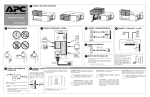
INSTALLATION
1
2
Placement
3
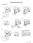
Remove Connector Cover
Remove Battery (if wall-mounting - if not proceed at Step 5)
w w w.apc.com
Back-UPS HS 500
User’s Manual
32 - 104oF (0 - 40oC)
NOTE: APC recommends your network equipment
(computer, modem, router, hub, or other networked
devices) be completely installed, configured, and
tested prior to adding this UPS to the network.
990-9234
4
Remove battery.
Press cover release
tab (one each side)
and remove cover.
Press the outlet cover release
tab (one each side); and pivot
cover off the unit.
Disconnect battery
wires from battery.
Caution: To prevent damage to the ribbon cable (not shown)
that connects the cover to the UPS, replace the cover after
removing the battery. Do not disconnect the ribbon cable
from the cover or the UPS.
2/04
Mount Back-UPS (optional)
5
6
Connect and Install Battery, Install Battery Cover
Connect Cable Modem,
DSS or CATV Receiver
to Surge Protection
(optional)
Wall Anchor
Mounting
Hole
Cable In
Cable Out
Circuit Breaker
Push to Reset
®
w w w.apc.com
Input:
120V~, 10A, 50-60Hz
7
Connect Phone Line
or DSL to Surge
Protection (optional)
Modem/Phone/Fax
RJ-45
Connectors
(will accept RJ-11)
Network
RJ-45
Connectors
Install battery cover.
To Hub or
Router
Wall
Press the outlet cover
release tab (one each
side); and pivot cover
off the unit.
8
Connect Network
Equipment
9
10
Connect Equipment
Power Cords
From Cable Provider
(Phone, Internet,
and/or CATV; or
DSS)
Connect and install
the battery..
Install Connector Cover
11
To Cable Modem,
VCR, DSS or TV
Cable Box
Connect to Power Source
and Switch on UPS Power
Phone Line In
(Standard or
DSL)
12
From Modem
Phone Line Out
Check the Building
Wiring Fault Indicator
Check the Building Wiring Fault indicator. If this
light emitting diode (LED) is illuminated, it is an
indication that a potential shock hazard exists. Have
the building wiring inspected and repaired by a
qualified electrician.
LAN
Network Device
Hub
or Router
Output 3
Output 1
From Network Device
(or Computer Using a
Crossover Cable)
Network Device
Modem
Output 3
Output 2
Align the holes in the
cover with the connector
cover release tabs (one
each side) and lower
connector cover.
Building Wiring
Fault Indicator
STATUS INDICATORS AND ALARMS
TRANSFER VOLTAGE/SENSITIVITY ADJUSTMENT (Optional)
There are six status indicators (lights) on the front panel of the Back-UPS (On Line, On Battery,
Overload, Replace Battery, TX/RX, and ACT/LNK).
On Line On Battery Overload Replace TX/RX ACT/LNK
Battery
On Line (green) - is illuminated whenever AC utility power
is supplying power the outlets.
Overload (red) - is illuminated whenever power demand
has exceeded the capacity of the Back-UPS.
Continuous Tone - this alarm is sounded
whenever the Back-UPS outlets are overloaded.
®
Back-UPS
HS500
w w w.apc.com
On Battery (yellow) - is illuminated whenever the BackUPS battery is supplying power to the equipment connected
to the outlets.
Four Beeps Every 30 Seconds - this alarm is
sounded whenever the Back-UPS is running On
Battery. Consider saving work-in-progress.
Continuous Beeping - this alarm is sounded
whenever a low battery condition is reached.
Battery run-time is very low. If supplying power to
a computer directly from the Back-UPS, promptly
save any work-in-progress and exit all open
applications. Shut down the operating system,
computer and the Back-UPS.
Replace Battery (red) - is illuminated whenever the
battery is near the end of its useful life, or if the battery is
not connected (see above). A battery that is near the end of
its useful life has insufficient run-time and should be
replaced.
Chirps for 1 Minute Every 5 Hours - this
alarm is sounded whenever the battery has failed
the automatic diagnostic test.
In situations where the Back-UPS or connected equipment appears too sensitive to input voltage, it may be
necessary to adjust the transfer voltage. This is a simple task requiring use of the front panel Power switch, or it
can also be accomplished using the Configuration Page Screen (Figure 16) in the supplied software (see Install
and Setup Software). To adjust the transfer voltage, proceed as follows:
1. Plug the Back-UPS into a the power source. The unit will be in a stand by mode (no indicators illuminated).
2. Press the front panel power switch fully inward for 10 seconds. All indicators on the Back-UPS will flash to
acknowledge going into Programming Mode.
3. The Back-UPS will then indicate its current Sensitivity Setting, as shown in the following table.
Indicators
Flashing
Sensitivity
Setting
Input Voltage
Range (for
utility
operation)
Use When
1
(yellow)
Low
88 - 142 Vac
Input voltage is extremely low or high. Not
recommended for computer loads.
2
(yellow, and red)
Medium
(factory default)
92 - 139 Vac
Back-UPS frequently goes On Battery
(recommended).
3
(yellow, red, and red)
High
96 - 136 Vac
Connected equipment is sensitive to voltage
fluctuations.
TX/RX (green) - is illuminated whenever the Back-UPS
is sending or receiving data over the network.
ACT/LNK (green) - is illuminated whenever the Back-
UPS is connected to equipment and is ready and waiting to
send or receive data.
Circuit Breaker - the circuit breaker button located on
the bottom panel of the Back-UPS will stick out if an
overload condition forces the Back-UPS to disconnect
itself from AC utility power. If the button sticks out,
disconnect non-essential equipment. Reset the circuit
breaker by pushing the button inward.
4. To select the Low Sensitivity setting, press the Power switch until the yellow indicator is flashing.
5. To select the Medium Sensitivity setting, press the Power switch until the yellow and red indicators are
flashing.
6. To select the High Sensitivity setting, press the Power switch until yellow and both red indicators are
flashing.
7. To exit without changing the Sensitivity Setting, press the Power switch until the green indicator is flashing.
8. Once in Programming Mode, if the Power switch is not pressed within 5 seconds, the Back-UPS will exit
Programming Mode; all indicators will extinguish.
INSTALL AND SETUP SOFTWARE
5. The software will display the Choose Destination Location Screen (Figure
4). Select Browse to find a location, click Next to accept the system default
location, the system will then display the Setup Status Screen (Figure 5).
Click on Cancel to stop the installation.
Follow the
on-screen
instructions.
6. The software then displays the InstallShield Wizard Complete Screen (Figure 6). Select
Finish to quit the installation program..
If Autoplay is enabled on your computer, the software on the CD-ROM will
automatically start the installation program.
If Autoplay is not enabled on the computer, proceed as follows:
1. On the computer desktop of the display, double-click on My Computer, or
start Windows Explorer to locate the computer’s CD-ROM drive icon.
2. Double-click on the CD-ROM drive icon and then double-click on the
setup.exe icon. The software will start and display the InstallShield
Wizard Screen (Figure 1). The software will begin the installation
process. To stop the installation, click Cancel.
Figure 6. InstallShield Wizard Complete Screen
Figure 2. InstallShield Welcome Screen
4. The software will then display the Licence Agreement (Figure 3). Please
read the Agreement and accept the terms by clicking Yes. To decline the
Agreement, click No - the software will not install.
7. To launch the program, go to the Start menu, select APC, then select APC Back-UPS HS
(Figure 7). Continued on the next page -
Figure 4. Choose Destination Location Screen
Figure 1. InstallShield Wizard Screen
3. After about 4 seconds, the software will display the Welcome Screen
(Figure 2). To continue, click Next. To cancel the installation, click
Cancel.
Figure 3. InstallShield Licence Agreement Screen
Figure 5. Setup Status Screen
Figure 7. APC Software Startup Menu Selections
8. Following installation, the Back-UPS HS software is available in the Start
menu. Upon launching the program, it searches for all Back-UPS HS devices on
the network, and will identify them as shown in Figure 8 by IP Address and
MAC Address. The IP Address is automatically assigned to the Back-UPS by
the DHCP services from your hub or router. IP Addresses assigned by the
DHCP service may automatically change over time. Thus, APC recommends
you do not bookmark the IP Address, as you may not be able to access it
through your browser. The MAC Address is assigned to the Back-UPS HS 500
at the factory.
.
Figure 11. Assign Name Screen
11. To reset the Back-UPS HS to factory default values, use the UPS Settings
button. If the Back-UPS HS does not reset using the software, remove the
Battery Cover and insert a small object (about 2 inches in length) into the hole
located next to the telephone jack (Figure 12) for approximately 5 seconds.
Note: The telephone jack is provided for factory testing only - do not connect
anything to this jack).
Figure 16. Configuration Page Screen
Figure 14. Log On Screen
Figure 8. Back-UPS HS IP Address and MAC Address Screen
9. If there are no DHCP services on the network, or if you want to assign an IP
Address you can easily remember, you can manually assign an IP Address to
the Back-UPS by clicking on the IP Configuration button. The address you
assign must follow the format shown in Figure 9 and cannot duplicate an
address already assigned. Figure 10 shows the IP Configuration Screen with the
IP Address fields set to zero (0).
To assign an IP Address to your computer, please read and follow the directions
that came with your computer.
Manual Reset
Access
14. Using the Maintenance Screen (Figure 15), you can perform a Battery SelfTest, Update the Battery Replacement Date, Change the User Name or
Password (as previously discussed) then click Update Now, or you can
Restore Factory Defaults. Note: You must be logged on to perform any of
these tasks.
16. The About Page Screen provides general information about your Back-UPS
including Network Parameters (IP and MAC Addresses), as well as Technical
Parameters (Model, Serial Number, Firmware Revision, Web Firmware
Revision, UPS Date of Manufacture, and Battery Replacement Date).
Figure 12. Manual Reset Access
12. Before performing any UPS maintenance task, check the Status of the UPS by
clicking on the Status link. The screen shown in Figure 13 will be displayed.
Figure 17 About Page Screen
Figure 15. Maintenance Page Screen
Figure 9. Assign IP Address Screen
Figure 13. Back-UPS HS 500 Status Screen
13. To change the configuration of the Back-UPS or perform UPS maintenance,
you must log on to the web page (Figure 11) by clicking on the UPS Settings
button.
When this page is displayed, enter a default Username of apc, and a default
Password of apc. To change the Username or Password, you must log on and
then click Maintenance (Figure 14).
Note: You can also access the Logon Page Screen by entering the IP Address
into the Address line of your browser.
15. Using the Configuration Page Screen (Figure 14), you can adjust the
Sensitivity of the Back-UPS. By adjusting the Sensitivity, the Back-UPS will
allow the unit to switch to battery power depending on the quality of the AC
utility power being supplied to the unit. Use of the Sensitivity settings are for
the following conditions:
Low - Use only for extreme conditions of low input voltage. Not recommended
for computer loads.
10. You can assign a name to the Back-UPS by clicking on the Assign Name
button (Figure 8) and entering the name in the Assign Name Screen dialog. It
will appear in the column to the left of the IP Address of the device (Figure 11).
Names should not be duplicated.
Input Voltage (On Line)
Input Frequency
95 - 142 Vac
47 - 63 HZ (autosensing)
Output Wave Form (On Battery)
Stepped Sine Wave
Maximum Load
500 VA 300 Watts
Operating Temperature
32 - 104° F (0 to 40° C)
Storage Temperature
5 - 113° F (-15 to 45° C)
High - Connected equipment is sensitive to low voltage.
Operating Humidity
10 - 90% non-condensing
The Configuration Page Screen also allows you to enable or disable the
Audible Alarm. If enabled, this alarm operates as described in the Status
Indicators and Alarms section of this manual. If disabled, the Back-UPS will
quiet the alarm.
Storage Humidity
10 - 95% non-condensing
Medium - Back-UPS frequently goes On Battery due to low input voltage
(recommended).
Additionally, the Configuration Page Screen allows you to adjust the voltage
Transfer Points. The Back-UPS will transfer to On Battery operation at input
voltages Above or Below the points selected in the drop-down Volts menu.
Figure 10. Blank Assign IP Address Screen
Specifications
Finally, the Configuration Page Screen provides Output Control for the four
outlets of the Back-UPS. Control consists of switching power On or Off at
Output 1, Output 2, or the two outlets of Output 3. It also allows you to
Reboot loads by automatically switching power Off and then On at the selected
outlet. If an outlet is switched Off, it cannot be rebooted.
To use the Configuration Page Screen, you must be logged on to the BackUPS. Select the desired function and click on the Apply button. To reset the
unit to the factory defaults, click the Reset button.
Physical: (D x W x H)
Weight
Typical Recharge Time
EMI Classification
Approvals
14.65 x 8.85 x 4.13 in
(37.2 x 22.5 x 10.5 cm)
16.3 lb (7.4 kg)
6 - 8 hours
FCC Part 15
UL, ULc, FCC Part 15
FCC Part 68, Industry Canada
Troubleshooting
Order Replacement Battery
Use the tables below to solve minor Back-UPS installation and operation problems. Consult APC On-line
Technical Support or call APC Technical Support for assistance with problems that cannot be resolved using
this document:
Possible Cause
Possible Cause
A red indicator is illuminated
Battery is not connected properly.
Procedure
Back-UPS will not switch on
Back-UPS not connected to an AC
power source.
Back-UPS circuit breaker “tripped”.
Very low or no AC utility power.
Check that the Back-UPS power plug is
securely connected to the wall outlet.
Disconnect non-essential equipment from the
Back-UPS. Reset the circuit breaker (located
on the bottom of the Back-UPS) by pushing
the circuit breaker button fully inward until it
catches. If the circuit breaker resets, switch
the Back-UPS on and reconnect the
equipment one-at-a-time. If the circuit
breaker trips again, the last connected device
is causing the overload.
Cable Out Cable In
Circuit Breaker
Push to Reset
Input:
120V~, 10A, 50-60Hz
Disconnect one or more equipment power plugs until the indicator is
no longer illuminated.
Battery requires replacement.
The battery should be replaced within two weeks (see "Order
Replacement Battery"). Failure to replace the battery will result in
reduced run-time during a power outage.
Replace Battery indicator illuminated / alarm sounds when the unit is turned on
Internal battery not connected.
Back-UPS failure.
Replace with an APC qualified battery. Replacement batteries can be ordered from APC Global Services. Have your
Back-UPS HS model number available when ordering. Your model number can be found on the bottom of the unit.
Warranty
The standard warranty is two (2) years from the date of purchase. APC’s standard procedure is to replace the original
unit with a factory reconditioned unit. APC will ship the replacement unit once the defective unit has been received
by the repair department, or cross-ship upon the receipt of a valid credit card number. The customer pays for shipping
the unit to APC. APC pays ground freight transportation costs to ship the replacement unit to the customer.
Warranty Registration
To register this product for purposes of the warranty, please go to warranty.apc.com.
APC Contact Information
Technical Support
Internet
USA and Canada
www.apc.com/support
www.apc.com
800-800-4272
Call APC for service.
ACT/Link Indicator is not illuminated
Connect another network device to the LAN connector.
Verify all network connections.
Check the battery connections. (See “Connect/Install Battery, Install
Battery Cover” under “Installation” on the front page of this
document.
TX/RX Indicators are flashing.
Back-UPS failure.
Contact APC technical support.
Unable to browse to Back-UPS HS
Back-UPS operates on battery although normal utility voltage exists
Disconnect non-essential equipment from the
Back-UPS. Reset the circuit breaker (located
on the bottom of the Back-UPS) by pushing
the circuit breaker button fully inward until it
catches.
Check the battery connections. Consult "Connect the Battery" under
"Installation" on the front page of this document. It shows how to
access the battery and connect the wires.
Red indicators are flashing
Check the wall outlet that supplies power to
the Back-UPS using a table lamp. If the lamp
bulb is very dim, have the AC utility power
checked by a qualified electrician.
Back-UPS does not supply power to network devices during an outage
Back-UPS circuit breaker “tripped”.
Check the battery connections. Consult "Connect/Install Battery,
Install Battery Cover", which shows how to access the battery and
connect the wires.
The
Overload
indicator
is
illuminated if equipment connected
to the Back-UPS outlets is drawing
more power than the Back-UPS can
provide.
Unable to link to the Ethernet port.
Internal battery is not connected.
Procedure
Cannot access the Web interface of
the Back-UPS.
Cable Out Cable In
Circuit Breaker
Push to Reset
Input:
120V~, 10A, 50-60Hz
The wall outlet that the Back-UPS is Connect the Back-UPS to another wall outlet or have a qualified
connected to does not supply AC electrician check the building wiring.
utility power to the unit.
Using the Back-UPS HS Software, check the assigned Internet
Protocol (IP) address of the Back-UPS. If the assigned address is
0.0.0.0, shut down the Back-UPS HS Software and then restart the
program. The equipment providing DHCP will reassign an IP Address
to the Back-UPS.
Verify you can “ping” the Back-UPS, as follows:
Open an MS-DOS window and enter the Ping Command as,
ping XXX.XXX.XXX.XXX (IP address of the device to be
“pinged”
If a message similar to the following appears, a communication link
between your computer and the device has been established:
Back-UPS does not provide expected backup time
Back-UPS is excessively loaded.
Unplug non-essential connected equipment, such as laser printers.
Note: Devices that have motors or dimmer switches (laser printers,
heaters, fans, lamps, and vacuum cleaners, for example) should not be
connected to the Back-UPS outlets.
Back-UPS battery is weak due to
recent outage and has not had time
to recharge.
Charge the battery. The battery charges whenever the Back-UPS is
connected to a wall outlet. Typically, eight hours of charging time are
needed to fully charge the battery from total discharge. Back-UPS
run-time is reduced until the battery is fully charged.
Battery requires replacement.
Replace battery (see Order Replacement Battery). Batteries typically
last 3-6 years, shorter if subjected to frequent power outages or
elevated temperatures.
Pinging XXX.XXX.X.X with 32 bytes of data
Reply from XXX.XXX.X.X: bytes=32=2ms TTL=64
If you get the following message,
Pinging XXX.XXX.X.X with 32 bytes of data
Request timed out.
there may be something wrong in your network configuration. Check
the following items in sequence:
1. Ensure the ethernet cable is properly connected.
2. Ensure TCP/IP is properly configured on your computer.
3. Check that the ACT/LNK and TX/RX LEDs are illuminated.
Verify that you are using Internet Explorer 5.0 (or higher), or
Netscape Navigator 7.0 (or higher).
Copyright © 2004 American Power Conversion. All rights reserved. APC and
Back-UPS are registered trademarks of American Power Conversion. All
other trademarks are the property of their respective owners.