1
OWNER MANUAL
MANUALE D’USO
UP2081
UP2161
UP2321
- AMPLIFIER
- AMPLIFICATORE
INDEX
INDICE
ENGLISH
SAFETY PRECAUTIONS
OPERATING PRECAUTIONS
DESCRIPTION
FRONT PANEL
REAR PANEL
OPERATION
LOUDSPEAKER CONNECTION
POWER SUPPLY VOLTAGE CHANGE
SPECIFICATIONS
EXAMPLE OF CONNECTIONS 4
5
6
6
7
10
10
11
12
13
ITALIANO
AVVERTENZE PER LA SICUREZZA PRECAUZIONI D’USO
DESCRIZIONE
PANNELLO FRONTALE
PANNELLO POSTERIORE
FUNZIONAMENTO
COLLEGAMENTO DEI DIFFUSORI ACUSTICI
CAMBIO TENSIONE DI FUNZIONAMENTO DELL’APPARECCHIO
DATI TECNICI
ESEMPIO COLLEGAMENTI
14
15
16
16
17
20
20
21
22
23
ENGLISH
SAFETY
PRECAUTIONS
IMPORTANT
Before connecting and using this product, please read this instruction manual carefully and
keep it on hand for future reference.
The manual is to be considered an integral part of this product and must accompany it
when it changes ownership as a reference for correct installation and use as well as for the
safety precautions.
RCF S.p.A. will not assume any responsibility for the incorrect installation and / or use of
this product.
IMPORTANT
WARNING: To prevent the risk of fire or electric shock, never expose this product to rain
or humidity.
WARNING
SAFETY PRECAUTIONS
1. All the precautions, in particular the safety ones, must be read with special
attention, as they provide important information.
2. POWER SUPPLY FROM MAINS
a. The mains voltage is sufficiently high to involve a risk of electrocution; therefore, never
install or connect this product with the power supply switched on.
b. Before powering up, make sure that all the connections have been made correctly and
the voltage of your mains corresponds to the voltage shown on the rating plate on the
unit, if not, please contact your RCF dealer.
c. The metallic parts of the unit are earthed by means of the power cable. An apparatus
with CLASS I construction shall be connected to a mains socket outlet with a protective
earthing connection.
d. Protect the power cable from damage; make sure it is positioned in a way that it
cannot be stepped on or crushed by objects.
e. To prevent the risk of electric shock, never open the product: there are no parts inside
that the user needs to access.
3. Make sure that no objects or liquids can get into this product, as this may cause a short
circuit. This apparatus shall not be exposed to dripping or splashing. No objects filled with
liquid, such as vases, shall be placed on this apparatus. No naked sources (such as lighted
candles) should be placed on this apparatus.
4. Never attempt to carry out any operations, modifications or repairs that are not expressly
described in this manual.
Contact your authorized service centre or qualified personnel should any of the following
occur:
- The product does not function (or functions in an anomalous way).
- The power supply cable has been damaged.
- Objects or liquids have got in the unit.
- The product has been subject to a heavy impact.
5. If this product is not used for a long period, disconnect the power cable.
6. If this product begins emitting any strange odours or smoke, switch it off immediately
and disconnect the power supply cable.
7. The terminals marked with the symbol
are HAZARDOUS LIVE and their connection
is to be made by an INSTRUCTED PERSON or the use of ready-made cables is required.
8. Do not connect this product to any equipment or accessories not foreseen.
For suspended installation, only use the dedicated anchoring points and do not try to hang
this product by using elements that are unsuitable or not specific for this purpose.
Also check the suitability of the support surface to which the product is anchored (wall,
ceiling, structure, etc.), and the components used for attachment (screw anchors, screws,
ENGLISH
brackets not supplied by RCF etc.), which must guarantee the security of the system /
installation over time, also considering, for example, the mechanical vibrations normally
generated by transducers.
To prevent the risk of falling equipment, do not stack multiple units of this product unless
this possibility is specified in the user manual.
9. RCF S.p.A. strongly recommends this product is only installed by professional
qualified installers (or specialised firms) who can ensure correct installation
and certify it according to the regulations in force.
The entire audio system must comply with the current standards and regulations
regarding electrical systems.
10. Supports and trolleys
The equipment should be only used on trolleys or supports, where necessary, that are
recommended by the manufacturer. The equipment / support / trolley assembly must be
moved with extreme caution. Sudden stops, excessive pushing force and uneven floors may
cause the assembly to overturn.
11. There are numerous mechanical and electrical factors to be considered when installing
a professional audio system (in addition to those which are strictly acoustic, such as sound
pressure, angles of coverage, frequency response, etc.).
12. Hearing loss
Exposure to high sound levels can cause permanent hearing loss. The acoustic pressure
level that leads to hearing loss is different from person to person and depends on the
duration of exposure. To prevent potentially dangerous exposure to high levels of acoustic
pressure, anyone who is exposed to these levels should use adequate protection devices.
When a transducer capable of producing high sound levels is being used, it is therefore
necessary to wear ear plugs or protective earphones.
See the technical specifications in loudspeaker instruction manuals to know their maximum
sound pressure levels.
OPERATING
PRECAUTIONS
IMPORTANT NOTES
To prevent the occurrence of noise on microphone / line signal cables, use screened cables
only and avoid putting them close to:
IMPORTANT NOTES
- Equipment that produces high-intensity electromagnetic fields (for example,
high power transformers)
- Mains cables
- Loudspeaker lines.
OPERATING PRECAUTIONS
- Do not obstruct the ventilation grilles of the unit. Situate this product far from any heat
sources and always ensure adequate air circulation around the ventilation grilles.
- Do not overload this product for a long time.
- Never force the control elements (keys, knobs, etc. ).
- Do not use solvents, alcohol, benzene or other volatile substances for cleaning the
external parts of this product.
OPERATING PRECAUTIONS
ENGLISH
RCF S.P.A. THANKS YOU FOR PURCHASING THIS PRODUCT, WHICH HAS BEEN
DESIGNED TO GUARANTEE RELIABILITY AND HIGH PERFORMANCES.
DESCRIPTION
UP 2081, UP 2161 and UP 2321 are amplifiers with a (mic / line) ‘MAIN INPUT’ on either
removable connector or XLR or RJ 45 (for quick connection of an RCF BM 3001 paging
microphone through CAT5 cable) and an ‘AUX INPUT’ for music sources (e.g. CD players,
tuners, etc.).
The 3 models have identical features, but their nominal power: 80 W (UP 2081), 160 W
(UP 2161), 320 W (UP 2321).
The amplifier output is available either for low impedance loudspeakers (min. 4 Ω) or
100 – 70 V constant voltage line (for loudspeakers having 100 – 70 V transformers).
About the ‘MAIN INPUT’:
- It can have priority over the AUX INPUT (by means of an external command linked to
either the removable connector or the RJ port).
- It has a ‘presence’ control and a separate high-pass filter that are useful for improving
speech intelligibility.
Front panel LEDs indicate the device state (ON, PROT), the priority activation (PRIOR) and
the signal / peak level (SIG/PK).
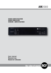
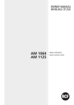
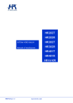
FRONT
PANEL
1
1 Amplifier MASTER volume control
2 LEDs:
ON
PROT
green: the device is switched on
red: overload protection
orange: thermal protection
PRIOR yellow: MAIN IN priority
SIG/PK green: the signal level is higher than – 15 dB
green + red: the signal level is in the 0 ÷ +2 dB range
red (peak): the signal level is equal or higher than +3 dB
2
3
ENGLISH
0 dB = signal level that allows to get the amplifier maximum power.
The internal ‘limiter’ circuit helps to avoid the amplifier overloading, yet it is advisable to reduce
MASTER volume when the SIG/PK LED is continuously indicating red.
the
3 Main POWER switch (0 = off; I = on)
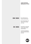
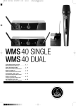
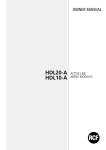
REAR
PANEL
13
12
11
10
4
9
5
6
7
8
4 MAIN INPUT settings through 5 dip-switches:
PRIORITY: the MAIN INPUT has priority over the
AUX INPUT when either the command has been
activated (CMD linked to GND on the removable
connector) or priority is taken from a paging
microphone connected to the RJ 45 port.
1
MIX – PRIORITY
MIX: the priority function is disabled
(the AUX INPUT is always open, even if the priority
command has been activated).
2
OFF – HIGH PASS
OFF: the audio hi-pass filter is not inserted (flat
frequency response).
HIGH PASS: the audio hi-pass filter is inserted.
3
OFF – PHANTOM
OFF: the PHANTOM power supply is disabled.
PHANTOM: the PHANTOM power supply is
enabled.
4
LOW LEV.
HIGH LEVEL
LOW LEVEL: the MAIN INPUT level is selectable
through the dip-switch no.5 between LINE
(– 20 dBu) and MIC.
HIGH LEVEL: the MAIN INPUT level is set to 0 dBu.
5
LINE – MICRO
LINE: the MAIN INPUT level is set to LINE
(– 20 dBu).
MICRO: the MAIN INPUT level is set to MIC.
ENGLISH
Examples of dip-switch 3, 4, 5 setting:
DIP 3
DIP 4
DIP 5
MODE
OFF
HIGH
LEVEL
---
HIGH LEVEL
dBu)
OFF
LOW
LEVEL
LINE
OFF
LOW
LEVEL
MICRO
PHANTOM
HIGH
LEVEL
PHANTOM
PHANTOM
USE (EXAMPLES)
(0
CD/MP3 players, tuners, message players, phone systems
LINE
(– 20 dBu)
Audio sources having – 20 dBu output level
MIC
Dynamic microphones
---
HIGH LEVEL
with PHANTOM
Pre-amplified (0 dBu output) paging microphone that needs
‘phantom’ power supply
LOW
LEVEL
LINE
LINE
with PHANTOM
BM 3001 paging microphone
LOW
LEVEL
MICRO
MIC
with PHANTOM
Electret microphones
When a BM 3001 paging microphone is used, it is necessary to choose the ‘LINE
with PHANTOM’ mode (dip-switch no.3 set to PHANTOM, dip-switch no.4 set to
LOW LEVEL, dip-switch no.5 set to LINE).
MAIN INPUT
MAIN INPUT
5 Removable connector:
1 +
hot audio input
2 -
cold audio input
3 GND
ground
4 CMD
priority command (ON: when linked to ground)
6 RJ 45 socket (i.e. useful to connect a BM 3001 paging microphone).
Note: when
BM 3001 paging microphone is connected , it is necessary to set the
3, 4 and 5 to the ‘LINE with PHANTOM’ mode ( see 4 MAIN INPUT
through 5 dip - switches ).
a
dip - switches
settings
PRIORITY
COMMAND
(TO GND)
Audio
signal
Green
GND
+
–
Blue
Orange
Orange/White
Brown
Brown/White
Green
Blue/White
Blue
Green/White
Orange
Orange/White
12 345 678
BM 3001 shall be set to ‘LOCAL’.
Cable with RJ 45 plug:
RJ
ENGLISH
7 XLR connector:
BALANCED CONNECTION
+
–
GND
hot
cold
ground
UNBALANCED CONNECTION
A lthough
the
MAIN INPUT
has
3
different connectors , these cannot be used to mix
different signals ; only one audio source can be connected .
T he 3
connectors are linked one another in parallel , therefore each input can be
used also as a ‘ thru ’ output to additional amplifier ( s ).
D o NOT
u s e a n unba l a n c e d c o nn e c t i o n w h e n t h e
‘P h a n to m ’
p o w e r s u p p ly i s
switched on.
8 MAIN INPUT PRESENCE CONTROL (f = 2.15 kHz)
AUX INPUT
AUX INPUT
9 AUX INPUT TREBLE and BASS controls.
0 AUX INPUT GAIN control.
{ AUX INPUT with dual RCA connector.
T he
two channels of the stereo source connected to the
AUX INPUT
are summed
internally ( to get a mono signal ).
}
Amplifier output (UP 2081: max. 80 W, UP 2161: max. 160 W, UP 2321: max.
320 W) to loudspeakers (100 / 70 V constant voltage line – 4 Ω impedance).
Use 1 output only (read the section ‘Loudspeaker connection’).
q Mains power cable input (with fuse)
Before connecting the power supply cable, verify that the apparatus voltage
(230 or 115 V ac) corresponds to the available mains supply.
N ote : the fuse type is marked on the rear
( below the mains power cable input ).
panel
ENGLISH
OPERATION
POWER ON (OR WHEN A PRIORITY COMMAND ENDS)
If no priority command is present, the MAIN INPUT and the AUX INPUT are mixed
together.
The music volume (i.e. CD player, tuner, etc., connected to the AUX INPUT) can be slightly adjusted
by the GAIN (10) control on the rear panel.
PRIORITY
If the priority command is present, the AUX INPUT is momentary muted (until the priority
ends).
THE 5 DIP-SWITCHES
The 5 dip-switches only affect the MAIN INPUT and allow to enable / disable the priority
function, set the input sensitivity, turn PHANTOM power supply on / off and insert the
high-pass filter.
RCF BM 3001 PAGING MICROPHONE (not included)
MAIN INPUT has also a RJ 45 socket, to which 1 (only) RCF BM 3001 paging microphone
can be connected.
Note: when a BM 3001 is connected, it is necessary to set the dip-switches 3, 4 and 5 to the “LINE
with PHANTOM” mode (see 4).
The BM 3001 paging microphone shall be set to ‘LOCAL’.
LOUDSPEAKER CONNECTION
Use 1 output only, DO NOT MIX 100 / 70 V and 4 Ω CONNECTIONS !
100 / 70 V CONSTANT VOLTAGE OUTPUTS
- Each loudspeaker shall have a line transformer with the
input voltage equal to the line voltage (100 / 70 V).
- The loudspeaker total power shall not be higher than
the amplifier maximum power.
100 V
70 V
10
ENGLISH
LOW IMPEDANCE OUTPUT (4 Ω)
- The loudspeaker total impedance shall not be lower than 4 Ω.
Note: a total impedance equal to 4 Ω allows the amplifier maximum power delivery. A
higher impedance leads to a reduction of the power delivered by the amplifier (e.g. 8
Ω: approx. ½ power, 16 Ω: approx. ¼ power). An impedance lower than 4 Ω overloads the amplifier.
- Loudspeaker models shall be chosen by considering the max. power (UP 2081: 80 W on
a 4 Ω load, UP 2161: 160 W on a 4 Ω load, UP 2321: 320 W on a 4 Ω load) that the
amplifier can deliver.
- Loudspeaker line should be as short as possible; long cables may need large wire crosssections.
- Do not use, at the same time, both the low impedance output (4 Ω) and the constant
voltage output (100V or 70V), as this overloads the amplifier.
POWER SUPPLY VOLTAGE CHANGE
IMPORTANT: This manual section is for qualified personnel only.
The following instructions are to be ignored by users.
IMPORTANT
Make sure the device is not connected to the mains (unplug the power supply cable).
Remove the lid.
In the picture 1, the voltage change connector is highlighted by a square.
PICTURE 1
If the mains voltage is 230 V, set the connector to the 230Vac position (see the picture 2),
according to the PCB indication (looking at the connector front, the central pin is connected
to the right one).
PICTURE 2
If the mains voltage is 115 V, set the connector to the 115 Vac position (see the picture 3),
according to the PCB indication (looking at the connector front, the central pin is connected
to the left one).
Refit the device lid.
PICTURE 3
Before connecting the device to the mains, make sure that the fuse (inside the IEC power
supply connector of the rear panel, see 13) is the correct current rating for the mains
voltages (read the fuse indication below the connector).
11
ENGLISH
SPECIFICATIONS
AMPLIFIER
Output (RMS) power
Frequency response
SIGNAL / NOISE RATIO
- MAIN INPUT
- AUX INPUT
Distortion (at 1 kHz, nominal power)
AUX INPUT tone controls
- Bass
- Treble
MAIN INPUT PRESENCE control
MAIN INPUT High-pass filter
INPUT SENSITIVITY / IMPEDANCE
LOW LEVEL – MICRO (main input)
LOW LEVEL – LINE (main input)
HIGH LEVEL (main input)
AUX INPUT
‘Phantom power’ voltage / current
LOUDSPEAKER OUTPUTS
Low impedance
Constant voltage (UP 2081)
Constant voltage (UP 2161)
Constant voltage (UP 2321)
PROTECTIONS
Amplifier
Power supply
GENERALE
Operating voltage
Max. consumption (power)
Dimensions (w, h, d)
Net weight
12
80 W (UP 2081),
160 W (UP 2161),
320 W (UP 2321)
50 Hz ÷ 13.5 kHz
60 dB
80 dB
< 0,3 %
± 8 dB @ 80 Hz
± 8 dB @ 13 kHz
+ 10 dB @ 2,15 kHz
150 Hz
Balanced, – 56 dBu (max – 25 dBu ) / 10 kΩ
Balanced, – 28 dBu (max 0 dBu) / 10 kΩ
Balanced, – 7 dBu (max + 19 dBu) / 10 kΩ
Adjustable – 4 ÷ + 15 dBu (max +22 dBu) / 20 kΩ
32 V / 18 mA
4Ω
70 V (63 Ω) / 100 V (125 Ω)
70 V (31 Ω) / 100 V (62 Ω)
70 V (16 Ω) / 100 V (31 Ω)
Overload, Short circuit, Thermal
fuses
115-230V / 50-60 Hz
160 W (UP 2081),
350 W (UP 2161),
600 W (UP 2321)
442 mm, 88 mm, 230 mm (2 unità rack 19”)
3.8 kg (UP 2081),
4.8 kg (UP 2161),
6.2 kg (UP 2321)
ENGLISH
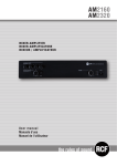
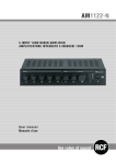
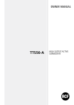
EXAMPLE OF CONNECTIONS
CD/DVD
BM 3001
MIXER
MIC.
(one only)
13
ITALIANO
AVVERTENZE PER
LA SICUREZZA
IMPORTANTE
Prima di collegare ed utilizzare questo prodotto, leggere attentamente le istruzioni
contenute in questo manuale, il quale è da conservare per riferimenti futuri.
Il presente manuale costituisce parte integrante del prodotto e deve accompagnare
quest’ultimo anche nei passaggi di proprietà, per permettere al nuovo proprietario di
conoscere le modalità d’installazione e d’utilizzo e le avvertenze per la sicurezza.
L’installazione e l’utilizzo errati del prodotto esimono la RCF S.p.A. da ogni responsabilità.
IMPORTANTE
ATTENZIONE: Per prevenire i rischi di fiamme o scosse elettriche, non esporre mai questo
prodotto alla pioggia o all’umidità.
ATTENZIONE
AVVERTENZE PER LA SICUREZZA
1. Tutte le avvertenze, in particolare quelle relative alla sicurezza, devono essere
lette con particolare attenzione, in quanto contengono importanti informazioni.
2. ALIMENTAZIONE DIRETTA DA RETE
a. La tensione di alimentazione dell’apparecchio ha un valore sufficientemente
alto da costituire un rischio di folgorazione per le persone: non procedere mai
all’installazione o connessione dell’apparecchio con l’alimentazione
inserita.
b. Prima di alimentare questo prodotto, assicurarsi che tutte le connessioni siano corrette
e che la tensione della vostra rete di alimentazione corrisponda quella di
targa dell’apparecchio, in caso contrario rivolgetevi ad un rivenditore RCF.
c. Le parti metalliche dell’apparecchio sono collegate a terra tramite il cavo di
alimentazione. Un apparecchio avente costruzione di CLASSE I deve essere connesso
alla presa di rete con un collegamento alla terra di protezione.
d. Accertarsi che il cavo di alimentazione dell’apparecchio non possa essere calpestato o
schiacciato da oggetti, al fine di salvaguardarne la perfetta integrità.
e. Per evitare il rischio di shock elettrici, non aprire mai l’apparecchio: all’interno
non vi sono parti che possono essere utilizzate dall’utente.
3. Impedire che oggetti o liquidi entrino all’interno del prodotto, perché potrebbero causare
un corto circuito. L’apparecchio non deve essere esposto a stillicidio o a spruzzi d’acqua;
nessun oggetto pieno di liquido, quali vasi, deve essere posto sull’apparecchio.
Nessuna sorgente di fiamma nuda (es. candele accese) deve essere posta
sull’apparecchio.
4. Non eseguire sul prodotto interventi / modifiche / riparazioni se non quelle espressamente
descritte sul manuale istruzioni.
Contattare centri di assistenza autorizzati o personale altamente qualificato quando:
- l’apparecchio non funziona (o funziona in modo anomalo);
- il cavo di alimentazione ha subito gravi danni;
- oggetti o liquidi sono entrati nell’apparecchio;
- l’apparecchio ha subito forti urti.
5.Qualora questo prodotto non sia utilizzato per lunghi periodi, scollegare il cavo
d’alimentazione.
6. Nel caso che dal prodotto provengano odori anomali o fumo, spegnerlo
immediatamente e scollegare il cavo d’alimentazione.
7. I terminali marcati con il simbolo
sono da ritenersi ATTIVI e PERICOLOSI ed il
loro collegamento deve essere effettuato da PERSONE ADDESTRATE oppure si devono
utilizzare cavi già pronti.
8. Non collegare a questo prodotto altri apparecchi e accessori non previsti.
Quando è prevista l’installazione sospesa, utilizzare solamente gli appositi punti di ancoraggio
e non cercare di appendere questo prodotto tramite elementi non idonei o previsti allo scopo.
14
ITALIANO
Verificare inoltre l’idoneità del supporto (parete, soffitto, struttura ecc., al quale è ancorato
il prodotto) e dei componenti utilizzati per il fissaggio (tasselli, viti, staffe non fornite
da RCF ecc.) che devono garantire la sicurezza dell’impianto / installazione nel tempo,
anche considerando, ad esempio, vibrazioni meccaniche normalmente generate da un
trasduttore.
Per evitare il pericolo di cadute, non sovrapporre fra loro più unità di questo prodotto,
quando questa possibilità non è espressamente contemplata dal manuale istruzioni.
9. La RCF S.p.A. raccomanda vivamente che l’installazione di questo prodotto
sia eseguita solamente da installatori professionali qualificati (oppure da ditte
specializzate) in grado di farla correttamente e certificarla in accordo con le
normative vigenti.
Tutto il sistema audio dovrà essere in conformità con le norme e le leggi vigenti
in materia di impianti elettrici.
10. Sostegni e Carrelli
Se previsto, il prodotto va utilizzato solo su carrelli o sostegni consigliati dal produttore.
L’insieme apparecchio-sostegno / carrello va mosso con estrema cura. Arresti improvvisi,
spinte eccessive e superfici irregolari o inclinate possono provocare il ribaltamento
dell’assieme.
11. Vi sono numerosi fattori meccanici ed elettrici da considerare quando si installa un
sistema audio professionale (oltre a quelli prettamente acustici, come la pressione sonora,
gli angoli di copertura, la risposta in frequenza, ecc.).
12. Perdita dell’udito
L’esposizione ad elevati livelli sonori può provocare la perdita permanente dell’udito. Il
livello di pressione acustica pericolosa per l’udito varia sensibilmente da persona a persona
e dipende dalla durata dell’esposizione. Per evitare un’esposizione potenzialmente
pericolosa ad elevati livelli di pressione acustica, è necessario che chiunque sia sottoposto
a tali livelli utilizzi delle adeguate protezioni; quando si fa funzionare un trasduttore in
grado di produrre elevati livelli sonori è necessario indossare dei tappi per orecchie o delle
cuffie protettive.
Consultare i dati tecnici contenuti nei manuali istruzioni per conoscere le massime pressioni
sonore che i diffusori acustici sono in grado di produrre.
PRECAUZIONI D’USO
NOTE IMPORTANTI
Per evitare fenomeni di rumorosità indotta sui cavi che trasportano segnali dai microfoni o di
linea (per esempio 0dB), usare solo cavi schermati ed evitare di posarli nelle vicinanze di:
- apparecchiature che producono campi elettromagnetici di forte intensità (per esempio
trasformatori di grande di potenza);
- cavi di rete;
- linee che alimentano altoparlanti.
NOTE IMPORTANTI
PRECAUZIONI D’USO
- Non ostruire le griglie di ventilazione dell’unità. Collocare il prodotto lontano da fonti di
calore e garantire la circolazione dell’aria in corrispondenza delle griglie di aerazione.
- Non sovraccaricare questo prodotto per lunghi periodi.
- Non forzare mai gli organi di comando (tasti, manopole ecc.).
- Non usare solventi, alcool, benzina o altre sostanze volatili per la pulitura delle parti
esterne dell’unità.
PRECAUZIONI D’USO
15
ITALIANO
RCF S.P.A. VI RINGRAZIA PER L’ACQUISTO DI QUESTO PRODOTTO, REALIZZATO
IN MODO DA GARANTIRNE L’AFFIDABILITÀ E PRESTAZIONI ELEVATE.
DESCRIZIONE
UP 2081, UP 2161 e UP 2321 sono amplificatori aventi un ingresso principale (mic.linea) “MAIN INPUT” disponibile su connettore rimovibile o XLR o RJ 45 (per la rapida
connessione di una base microfonica dedicata BM 3001 utilizzando un cavo CAT5); è
presente inoltre un ingresso ausiliario “AUX INPUT” per l’eventuale collegamento di una
sorgente musicale (es. lettore CD, sintonizzatore radio, ecc.).
Gli amplificatori UP 2081, UP 2161 e UP 2321 hanno caratteristiche identiche, tranne la
loro potenza nominale: 80 W (modello UP 2081), 160 W (UP 2161), 320 W (UP 2321).
L’uscita per diffusori acustici è disponibile sia a bassa impedenza (min. 4 Ω) oppure a
tensione costante 100 – 70 V (per diffusori con trasformatore).
L’ingresso “MAIN INPUT”:
- può ottenere la priorità sull’ingresso ausiliario AUX INPUT (tramite un comando esterno
collegato al connettore rimovibile od all’ingresso RJ);
- ha un controllo di “presenza” ed un filtro passa-alto utile per migliorare l’intelligibilità
della voce.
Sono presenti indicatori luminosi relativi allo stato dell’apparecchio (ON, PROT),
all’attività del circuito di priorità (PRIOR) ed al livello del segnale audio / picco (SIG/PK).
PANNELLO FRONTALE
1
1 Controllo di volume principale (MASTER) dell’amplificatore.
2 Indicatori luminosi (LED)
ON
verde: l’apparecchio è acceso
PROT
rosso: l’apparecchio è in protezione per sovraccarico
arancio: l’apparecchio è in protezione per riscaldamento eccessivo
PRIOR giallo: indica l’attivazione della priorità dell’ingresso MAIN INPUT.
SIG/PK verde: il livello del segnale audio è superiore ad almeno -15 dB
verde + rosso: il livello del segnale audio è compreso tra 0 e +2 dB
rosso (picco): il livello del segnale audio è uguale o superiore a +3 dB
16
2
3
ITALIANO
0 dB = livello del segnale che permette di ottenere la massima potenza erogata dall’amplificatore.
Il circuito “limiter” interno evita il superamento della potenza massima dell’amplificatore, tuttavia è
consigliabile abbassare il volume MASTER quando il LED SIG/PK è costantemente rosso.
3
Interruttore principale dell’apparecchio POWER (0 = spento; I = acceso)
PANNELLO POSTERIORE
13
12
11
10
4
9
5
6
7
8
4 Impostazione dell’ingresso MAIN INPUT tramite 5 microinterruttori “dip-switch”:
PRIORITY: l’ingresso principale MAIN INPUT è
prioritario sull’ingresso ausiliario AUX INPUT
quando si attiva il comando di priorità (CMD
sul connettore estraibile oppure da una base
microfonica collegata all’ingresso RJ 45).
1
MIX – PRIORITY
MIX: la funzione di priorità è disattivata (l’ingresso
ausiliario AUX INPUT è sempre aperto anche nel
caso che il comando di priorità sia stato attivato).
2
OFF – HIGH PASS
OFF: il filtro passa-alto è disinserito (risposta in
frequenza lineare).
HIGH PASS: il filtro passa-alto è inserito.
3
OFF – PHANTOM
OFF: l’alimentazione “phantom” è disattivata.
PHANTOM: l’alimentazione “phantom” è
presente.
4
LOW LEV.
HIGH LEVEL
LOW LEVEL: la sensibilità dell’ingresso audio MAIN
INPUT è selezionabile tramite il microinterruttore
nr.5 tra il livello “LINE” (-20 dBu) e microfonico.
HIGH LEVEL: la sensibilità ingresso audio
MAIN INPUT è impostata al livello 0 dBu.
5
LINE – MICRO
LINE: la sensibilità dell’ingresso audio MAIN INPUT
è impostata al livello linea (“LINE”, - 20 dBu).
MICRO: la sensibilità dell’ingresso
audio MAIN INPUT è impostata al livello
microfonico.
17
ITALIANO
Esempi di utilizzo dei microinterruttori 3, 4, 5:
DIP 3
DIP 4
DIP 5
MODO
ESEMPI DI POSSIBILI COLLEGAMENTI
OFF
HIGH
LEVEL
---
LIVELLO ALTO (0
dBu)
Lettore CD/MP3, radio, riproduttore di messaggi, centrale
telefonica
OFF
LOW
LEVEL
LINE
LIVELLO LINEA
(– 20 dBu)
Sorgente audio con uscita a livello – 20 dBu
OFF
LOW
LEVEL
MICRO
LIVELLO
MICROFONICO
Microfono dinamico
PHANTOM
HIGH
LEVEL
---
LIVELLO ALTO
con PHANTOM
Base microfonica preamplificata (con uscita a livello 0 dBu)
che necessita di alimentazione “phantom”
PHANTOM
LOW
LEVEL
LINE
LIVELLO LINEA
con PHANTOM
Base microfonica BM 3001
PHANTOM
LOW
LEVEL
MICRO
LIVELLO MIC.
con PHANTOM
Microfono ad elettrete
Quando si utilizza una base microfonica BM 3001, è necessario impostare il modo
“LIVELLO LINEA con PHANTOM” (microinterruttori: nr.3 su PHANTOM, nr.4 su
LOW LEVEL, nr.5 su LINE).
INGRESSO AUDIO PRINCIPALE “MAIN INPUT”
5 Connettore rimovibile:
INGRESSO AUDIO PRINCIPALE
“MAIN INPUT”
1 +
Ingresso audio positivo
2 -
Ingresso audio negativo
3 GND
massa
4 CMD
comando per ottenere la priorità quando connesso a massa (GND)
6
Connettore RJ 45, utilizzabile ad esempio per il collegamento di una base
microfonica RCF BM 3001.
Nota: nel caso sia utilizzata una base microfonica BM 3001, è necessario impostare il modo
“LIVELLO LINEA con PHANTOM” tramite i microinterruttori 3, 4 e 5 (vedere il precedente
punto 4).
COMANDO
(verso massa)
per priorità
Segnale
audio
verde
GND
+
–
Blu
Arancio
Biancoarancio
Marrone
Biancomarrone
Verde
Biancoblù
Blu
Biancoverde
Arancio
Biancoarancio
1 23 4567 8
La base microfonica BM 3001 dovrà essere impostata su “LOCAL”.
Cavo con connettore RJ 45:
RJ
18
ITALIANO
7 Connettore XLR:
COLLEGAMENTO BILANCIATO
+
polo positivo
–
polo negativo
GND massa
COLLEGAMENTO SBILANCIATO
A nche
se l ’ ingresso audio
MAIN INPUT
dispone di
3
diversi connettori , non è possibile
miscelare insieme segnali diversi ; si può collegare una sola sorgente audio .
Il
segnale audio è in parallelo su tutti i tre connettori , pertanto ciascun ingresso può
essere usato come uscita utile al fine di collegare uno o più amplificatori addizionali .
NON utilizzare il collegamento sbilanciato quando l’alimentazione “Phantom” è attiva.
8 Controllo di “presenza” (toni medi: f = 2,15 kHz) PRESENCE CONTROL (del
solo ingresso audio principale MAIN INPUT).
INGRESSO AUDIO AUSILIARIO “AUX INPUT”
9 Controlli di tono TREBLE (alti) e BASS (bassi) dell’ingresso ausiliario AUX INPUT.
INGRESSO AUDIO AUSILIARIO
“AUX INPUT”
0 Controllo di guadagno GAIN dell’ingresso ausiliario AUX INPUT.
{ Ingresso audio ausiliario AUX INPUT con doppio connettore RCA.
I
due canali del segnale stereo presente all ’ ingresso
AUX INPUT
sono sommati in
mono all ’ interno dell ’ apparecchio .
}
Uscite di potenza (max. 80 W per il modello UP 2081, max. 160 W per UP
2161, max. 320 W per UP 2321) per i diffusori (a tensione costante 100 / 70 V; a
bassa impedenza 4 Ω).
Utilizzare una sola uscita e vedere la sezione “Collegamento dei diffusori
acustici”.
q Connettore con fusibile per l’alimentazione principale da rete.
Prima di effettuare il collegamento, verificare che la tensione di rete corrisponda
a quella impostata (230 o 115 V) nell’apparecchio.
N ota : il tipo di fusibile
( sotto il connettore ).
da utilizzarsi è specificato sul pannello posteriore
19
ITALIANO
FUNZIONAMENTO
FUNZIONAMENTO ALL’ACCENSIONE (oppure al termine di una priorità)
In assenza del comando di priorità, si ha la miscelazione dell’ingresso audio principale
MAIN INPUT con quello ausiliario AUX INPUT.
Il volume della sorgente musicale (es. lettore CD, radio, ecc., collegata ad un ingresso AUX
INPUT) può essere in parte regolato tramite il controllo di guadagno GAIN (10) posto sul pannello
posteriore.
PRIORITÀ
In presenza del comando di priorità, l’ingresso ausiliario AUX INPUT è momentaneamente
disattivato (fino al termine della priorità stessa).
I 5 MICROINTERRUTTORI / DIP-SWITCH:
agiscono sul solo ingresso audio principale MAIN INPUT, permettendo di abilitare la
funzione di priorità, impostare la sensibilità d’ingresso, attivare l’alimentazione PHANTOM
ed, inserire il filtro passa-alto.
BASE MICROFONICA RCF BM 3001 (NON INCLUSA)
L’ingresso audio principale MAIN INPUT ha un ingresso con connettore RJ 45, al quale è
possibile collegare una sola base microfonica RCF BM 3001.
Nota: in tal caso è necessario impostare i microinterruttori 3, 4 e 5 (vedere il punto 4) nel modo
“LIVELLO LINEA con PHANTOM”.
La base microfonica BM 3001 dovrà essere impostata su “LOCAL”.
COLLEGAMENTO DEI DIFFUSORI ACUSTICI
Utilizzare una sola uscita tra le 3 disponibili: 100 V, 70 V, 4 Ω.
USCITE A TENSIONE COSTANTE 70 / 100 V
100 V
- Ogni diffusore deve avere un trasformatore di linea con
tensione d’ingresso uguale a quella della linea (70 /
100 V).
- La somma delle potenze di tutti i diffusori collegati
non deve essere superiore a quella massima erogabile
dall’amplificatore.
70 V
20
ITALIANO
USCITA BASSA IMPEDENZA (4 Ω)
- L’impedenza totale dei diffusori non deve essere inferiore a 4 Ω. Nota: un’impedenza complessiva uguale a 4 Ω permette la massima erogazione di
potenza dell’amplificatore; un’impedenza superiore comporta una riduzione della
potenza erogata (es. 8 Ω: circa ½ potenza; 16 Ω: circa ¼ potenza); un’impedenza
inferiore a 4 Ω sovraccarica l’amplificatore.
- La somma delle potenze dei diffusori deve essere adeguata alla potenza massima
erogabile dall’amplificatore (UP 2081: 80 W su 4 Ω; UP 2161: 160 W su 4 Ω; UP 2321:
320 W su 4 Ω).
- La lunghezza delle linee diffusori deve essere ridotta al minimo (una lunga distanza può
richiedere l’uso di cavi con sezioni elevate).
- Non utilizzare contemporaneamente il collegamento a bassa impedenza (4 Ω) e quello
ad alta impedenza (70V o 100V); fare ciò sovraccarica l’amplificatore.
CAMBIO TENSIONE DI FUNZIONAMENTO
DELL’APPARECCHIO
IMPORTANTE: La presente sezione del manuale riguarda il solo personale qualificato.
Le seguenti operazioni NON devono essere effettuate direttamente dall’utente.
IMPORTANTE
Togliere la tensione dall’apparecchio (staccando il cavo d’alimentazione dalla presa di rete).
Rimuovere il coperchio superiore dell’apparecchio.
Individuare il connettore per il cambio di tensione 230 / 115 V dell’alimentatore (nella foto
1 è evidenziato con un quadrato).
FOTO 1
Con tensione di rete 230 V, porre (o lasciare) il connettore nella posizione 230Vac (vedere
la foto 2) in accordo con la serigrafia del circuito stampato (in modo che il polo centrale sia
collegato a quello destro, guardando il connettore frontalmente).
FOTO 2
Con tensione di rete 115 V, porre (o lasciare) il connettore nella posizione 115Vac (vedere
la foto 3) in accordo con la serigrafia del circuito stampato (in modo che il polo centrale sia
collegato a quello sinistro, guardando il connettore frontalmente).
Rimontare il coperchio superiore dell’apparecchio.
FOTO 3
Prima di collegare l’apparecchio rete, assicurarsi che il fusibile inserito nel connettore per
l’alimentazione (posto sul pannello posteriore) sia quello corretto per la tensione in uso
(leggere le indicazioni poste sotto il connettore stesso).
21
ITALIANO
DATI TECNICI
AMPLIFICATORE
Potenza d’uscita (RMS)
Risposta in frequenza
RAPPORTO SEGNALE / RUMORE
- MAIN INPUT
- AUX INPUT
Distorsione (a 1 kHz, potenza nom.)
Controlli toni AUX INPUT
- Bass
- Treble
Controllo PRESENCE (MAIN INPUT)
Filtro passa-alto (MAIN INPUT)
SENSIBILITÀ D’INGRESSO / IMPEDENZA
LOW LEVEL – MICRO (main input)
LOW LEVEL – LINE (main input)
HIGH LEVEL (main input)
AUX INPUT
Tensione / corrente “Phantom power”
USCITE DIFFUSORI
Bassa impedenza
Tensione costante (UP 2081)
Tensione costante (UP 2161)
Tensione costante (UP 2321)
PROTEZIONI
Amplificatore
Alimentazione
GENERALE
Tensione di alimentazione
Max. potenza assorbita (consumo)
Dimensioni (l, h, p)
Peso (Netto)
22
80 W (UP 2081);
160 W (UP 2161);
320 W (UP 2321)
50 Hz ÷ 13,5 kHz
60 dB
80 dB
< 0,3 %
± 8 dB @ 80 Hz
± 8 dB @ 13 kHz
+ 10 dB @ 2,15 kHz
150 Hz
Bilanciato, – 56 dBu (max – 25 dBu ) / 10 kΩ
Bilanciato, – 28 dBu (max 0 dBu) / 10 kΩ
Bilanciato, – 7 dBu (max + 19 dBu) / 10 kΩ
Regolabile – 4 ÷ + 15 dBu (max +22 dBu) / 20 kΩ
32 V / 18 mA
4Ω
70 V (63 Ω) / 100 V (125 Ω)
70 V (31 Ω) / 100 V (62 Ω)
70 V (16 Ω) / 100 V (31 Ω)
Sovraccarico, cortocircuito, termica
Fusibili di rete
115-230V / 50-60 Hz
160 W (UP 2081),
350 W (UP 2161),
600 W (UP 2321)
442 mm, 88 mm, 230 mm (2 unità rack 19”)
3,8 kg (UP 2081);
4,8 kg (UP 2161);
6,2 kg (UP 2321)
ITALIANO
ESEMPIO COLLEGAMENTI
CD/DVD
BM 3001
MIXER
MIC.
(solo uno)
23
RCF SpA: Via Raffaello, 13 - 42124 Reggio Emilia > Italy
tel. +39 0522 274411 - fax +39 0522 274484 - e-mail: [email protected]
10307188 RevB
www.rcfaudio.com