1
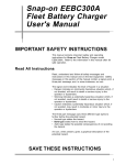
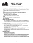
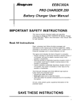
Snap-on BC5500B Super 550 Battery Charger User's Manual IMPORTANT SAFETY INSTRUCTIONS This manual contains important safety and operating instructions for Snap-on Super 550 Battery Charger model BC5500B. Refer to this manual often for information on safe operation. Product Number BC5500B BC5500BGY BC5500BPC BC5500BPF BC5500BPM BC5500BPQ Description Red battery charger Grey battery charger Black battery charger Teal battery charger Berry battery charger Yellow battery charger Read All Instructions Read, understand and follow all safety messages and instructions in this manual and on the test equipment. Safety messages in this section of the manual contain a signal word, a three-part message, and, in some instances, an icon. The signal word indicates the level of hazard in a situation: • Danger indicates an imminently hazardous situation which, if not avoided, will result in death or serious injury to the operator or bystanders. • Warning indicates a potentially hazardous situation which, if not avoided, could result in death or serious injury to the operator or bystanders. The three-part message uses three different type styles to further define the potential hazard. • Normal type states the hazard. • Bold type states how to avoid the hazard. • Italic type states the possible consequences of not avoiding the hazard. An icon, when present, gives a graphical description of the potential hazard. SAVE THESE INSTRUCTIONS 1 Safety Information Battery Gases, Charging Preparation and Charger Location Risk of explosion. Gases produced by a battery are highly explosive. • Wear safety goggles and protective clothing, user and bystander. • Use charger in an area having at least 4 air changes per hour. • Read, understand and follow all instructions for charger, battery, vehicle and any equipment used near battery and charger. • Do not obstruct vents on charger housing. • Do not smoke, strike a match, place metal tools on battery or cause a spark in the vicinity of the battery. When removing battery cables, remove ground cable first. • Clean terminals before charging battery. During cleaning, keep airborne corrosion from eyes, nose and mouth. Use baking soda and water to neutralize acid and help eliminate airborne corrosion. • Never allow clamps on charger cables to touch each other. • Do not expose charger to rain, snow or wet conditions. • Do not allow battery gasses or acid to contact charger cabinet. Do not place charger directly above or below battery. • Fill battery to level specified by battery manufacturer using distilled water. • Remove or do not remove cell caps while charging per manufacturer's instructions. • Make sure charger cable clamps make tight connections. Battery explosion can cause injury. Acid Burns Battery acid is highly corrosive sulfuric acid. • Wear safety goggles, user and bystander. • Wear protective gloves. • Make sure someone can hear you or is close enough to provide aid when working near battery. • Have plenty of fresh water and soap nearby. If battery acid contacts skin, clothing or eyes, flush the exposed area with soap and water for 10 minutes. Seek medical help. • Do not touch eyes while working near battery. Battery acid can burn eyes and skin. 2 Safety Information Grounding, AC Power Cord Connections and General Charger Use Risk of electric shock and fire. • Before connecting power cord to outlet make sure controls are set to OFF. • Do not remove or bypass the grounding pin. • Do not operate charger with damaged cord or plug. Replace cord or plug immediately. • Position power cord and charger cables away from the hood, doors or hot/moving engine parts where they could be damaged. • Use extension cord only when absolutely necessary. An extension cord up to 25 feet must be 18 AWG, up to 50 feet must be 14 AWG, up to 100 feet must be 12 AWG and up to 150 feet must be 10 AWG and extension cord plug and charger plug must have the same number, size and shape of pins. • Unplug power cord using plug rather than cord when disconnecting charger from outlet. • Charger power cord uses equipment-grounding conductor and a grounding plug. Plug only into a three-prong 120 VAC outlet that is correctly installed and grounded in accordance with all ordinances and local codes. • When using an adapter refer to Figure 1. • Unplug power cord from outlet before cleaning or maintaining charger. Turning off controls will not reduce this risk. • Do not operate charger after a sharp impact, dropping or any other damage. Do not disassemble charger. Call Snap-on/Sun Representative for repairs. • Use only recommended attachments. • Do not charge a frozen battery. Do not overcharge a battery. • Use charger only for lead-acid automotive batteries and for automotive cranking assist using procedure in this manual. Do not use charger for charging dry-cell batteries. Electric shock or fire can cause injury. 3 Safety Information Refer to Figure 1. Use the charger on a nominal 120 VAC circuit that has a grounding outlet that looks like B. An adaptor can be used, such as one like E to connect the plug to a twopole outlet like C, until a properly grounded outlet can be installed by a qualified electrician. Figure 1: Outlet and Plug Configurations A B C D – – – – Charger Power Cord Plug Grounded Power Outlet Ungrounded Power Outlet Green Grounding Lug, must be properly grounded * E – Grounding Adaptor *If necessary, replace original outlet cover plate screw with a longer screw that will secure adaptor ear or lug to outlet cover plate, making ground connection to grounded outlet. Risk of entanglement. Keep yourself, clothing and battery charger leads clear of moving parts such as fan blades, pulleys, hood, and doors. Moving parts can cause injury. Thermal Burns Risk of burns. Batteries can produce a short-circuit current high enough to weld jewelry to metal. Remove jewelry such as rings, bracelets and watches before working near batteries. Short circuits can cause injury. 4 Safety Information Charging Instructions Follow the information in this section to help ensure safety when connecting the charger cables to battery. For additional information refer to Battery Charging Procedure. Battery in Vehicle Use this information when charging battery in vehicle. • Do not charge automotive batteries installed in boats. Remove the battery and charge on shore. Onboard charging requires equipment designed for marine use. • Identify battery terminal polarity. — Negative terminal may be marked NEG, N or –. — Positive terminal may be marked POS, P or +. ✓ The positive terminal is usually larger diameter than the negative terminal on batteries with top terminals. • Identify system ground. — Negative ground system has negative terminal connected to chassis. This is the most common type. — Positive ground system has positive terminal connected to chassis. Negative Ground • Connect positive charger cable clamp—red—to positive battery terminal. • Connect negative charger cable clamp—black—to vehicle chassis, heavy gauge metal part of frame or engine block, away from battery. ✓ Do not connect the ground clamp to the carburetor, fuel line or body sheet metal. Positive Ground • Connect negative charger cable clamp—black—to negative battery terminal. • Connect positive charger cable clamp—red—to vehicle chassis, heavy gauge metal part of frame, or engine block away from battery. ✓ Do not connect the ground clamp to the carburetor, fuel line or body sheet metal. 5 Safety Information Disconnecting Charger • Turn Length of Charge Timer to OFF, • Disconnect power cord, • Remove clamp from ground, and • Remove clamp from battery terminal. Battery Not in Vehicle Follow this procedure when charging battery out of vehicle. • Identify battery terminal polarity. — Negative terminal may be marked NEG, N or –. — Positive terminal may be marked POS, P or +. ✓ The positive terminal is usually larger diameter than the negative terminal on battery with top terminals. • Attach at least a 24 inch long 6 gauge (AWG) insulated battery cable to negative terminal. — When charging side terminal battery out of vehicle, use side terminal adaptors. • Connect positive charger cable clamp—red—to positive battery terminal. • Position yourself and free end of cable as far away from battery as possible, then connect negative charger cable clamp—black—to free end of cable previously installed. Do not face battery when making final connection. Disconnecting Charger • Turn Length of Charge Timer to OFF, • Disconnect power cord, • Remove clamp from negative cable, and • Remove clamp from positive terminal. ✓ Always disconnect charger in reverse sequence of connecting procedure. Stand as far away as possible and face away from the battery when disconnecting ground clamp from cable connection. 6 BC5500B Operating Instructions Use this section for information about using the BC5500B Super 550 Battery Charger correctly and safely. The following are included. • Functional Description, • Battery Charging, • Maintenance, • Cranking Assist, • Assembly, and • Parts List. Functional Description The BC5500B Super 550 Battery Charger is a constant voltage, taper rate charger. The voltage across the battery remains nearly constant while the charge current decreases or tapers as the battery approaches full charge. The following information describes control panel features of the charger. Figure 2: Control Panel 7 Operating Instructions BC5500B A—Coarse Rate Range Switch Selects volts for charge. Range settings are: — 6 LO, — 6HI, — 12 LO, or — 12 HI. B—Fine Rate Range Switch Selects volts for charge. Range settings are: — LO, — 2 REG, — 3 HYBRID, or — HI MAIN FREE. C—Ammeter Meter Displays amps, 0 to 100 ADC, flowing from charger into battery. D—Length of Charge Timer Selects charger power mode and charge duration with manual or automatic shut-off functions. • OFF electrically shuts off power to the charger. — Select before connecting or disconnecting power cord or any leads. • HOLD powers charger until OFF is manually selected. — Select when desired charge time exceeds 120 minutes. Charger does not turn off automatically when this function is selected. • CHARGE TIME is number of minutes the charger operates before automatically shut-off. Charger shuts off automatically after number of minutes selected lapse when this function is selected. — Up to 120 minutes can be selected. Increase or decrease charge time as needed by selecting new time. ✓ The charger automatically shuts off when the charge time reaches zero. 8 BC5500B Operating Instructions Battery Charging Procedure 1. Perform visual inspection of battery(ies) before charging to help prevent personal injury and property damage. Check the following conditions, correcting defects and/or replacing battery(ies) and components as required. — Cracked case. — Improper electrolyte level - fill to level specified by battery manufacturer. — Frozen electrolyte or resulting damage. — Loose or corroded terminal/cable connection. — Frayed or broken cables. — Loose or over-tightened battery hold-down. — Correct size and capacity for vehicle. 2. Set the Coarse Rate or Fine Rate switch. Determine battery voltage from vehicle owner's manual or battery instructions. Use: — 6 LO or 6HI (6 volt battery), — 12 LO or 12HI (12 volt battery), — LO (Charges at a low voltage. Useful for extended charging or finish charging on any lead/acid battery.), — 2 REG (Charges at a slightly increased voltage. To be used for regular lead/acid or conventional batteries.), — 3 HYBRID (Charges at a higher voltage. Select this setting for batteries that use combinations of lead antimony on positive plates and calcium lead on negative plates. Hybrid batteries use porous plates saturated with electrolyte and fiberglass plate separators. These "recombination" batteries are sold under such brand names as Chloride's Torque Starter and GNB's Cathanode.), or — HI MAINT FREE (Charges at the highest voltage needed for the "maintenance-free" battery types. These are typically calcium grid type internal construction batteries such as the Delco Freedom batteries.). 3. Measure and record battery state of charge. — Specific gravity. — Open circuit voltage. ✓ State of charge is used in step 9 to determine charge time. 4. Verify AC power cord is disconnected from outlet and Length of Charge Timer is set to OFF. 9 Operating Instructions BC5500B 5. Connect charger cables to battery and power cord to outlet. For additional information refer to Important Safety Instructions–Charging Instructions. • Never alter AC cord or plug provided. If it will not fit outlet, have proper outlet installed by a qualified electrician. • Read, understand and follow Safety Information in front of this manual. 6. Set Length of Charge Timer to HOLD. 7. Observe DC AMPS. Some reading should be evident. — If OK, allow to stabilize for 5 minutes. Recheck DC AMPS reading. — If not, set Length of Charge Timer to OFF. Determine reason for no reading. Correct before proceeding. 8. Determine battery capacity. Capacity is usually marked on battery and rated in: — Ampere-Hours (AH), — Reserve Capacity (RC), or — Cold Cranking Amps (CCA). ✓ Battery capacity is used in step 9 to determine charge time. 9. Determine charge time using Chart 1. ✓ A battery charged 25% or lower may easily freeze, charge immediately. Example: A battery is determined to be medium capacity since its CCA rating is 405 and Reserve Capacity is 90 minutes. Open circuit voltage test shows 12.1 volts, indicating about a 50% charge. Five minutes after the charger is powered up, charging current is 20 amps. Therefore, battery should be charged for 60 to 90 minutes, as shown on the chart. 10 BC5500B Operating Instructions STATE-OF CHARGE STATE-OF-CHARGE 6 & 12V Specific Gravity 12V Open Circuit Voltage 6 V Open Circuit Voltage 100% 1.260 12.6 6.3 75% 1.225 12.4 6.2 50% 1.185 12.1 6.1 25% 1.140 11.9 6.0 BATTERY CAPACITY Battery Voltage 6V DEAD 1.110 11.8 5.9 12V SMALL MEDIUM LARGE Battery Capacity SMALL MEDIUM LARGE 100 155 200+ Ampere hours 40 60 80+ 160 275 430+ Reserve Capacity 60 90 100+ 500 700 900+ Cold Cranking Amps 300 400 500+ BATTERY CAPACITY % CHARGE LENGTH OF CHARGE TABLE BEGINNING AMPS CHARGE RATE Small 0-25 25-50 50-75 45 30 15 30 20 10 30 20 10 25 15 10 25 15 5 20 10 5 Medium 0-25 25-50 50-75 70 45 25 50 30 15 45 25 15 40 20 15 35 20 10 30 20 10 Large 10-25 25-50 50-75 90 60 30 55 40 20 55 34 20 50 30 15 45 30 15 45 30 15 15 30 45 60 75 90 APPROXIMATE MINUTES OF CHARGE Chart 1: Determining Length of Charge using State of Charge and Capacity 10. Set required charge time on Length of Charge Timer. If charge time exceeds 120 minutes, perform one of following. — Set Length of Charge Timer for any portion of total charge time. Reset timer for remaining time when charge time ends. — Reset Length of Charge Timer at any time to extend amount of charge time until total time required is reached. — Set Length of Charge Timer to HOLD and manually turn charger off when required time is reached. Charger does not turn off automatically. Overcharging can damage battery. 11. Periodically monitor state of charge to prevent overcharging, especially near end of charge period. Battery is completely charged when specific gravity and/or charging voltage do not increase after two hours. 11 Operating Instructions BC5500B Charging More than One Battery Passenger vehicles and light trucks with diesel engines may use two batteries. Heavy-duty trucks, special service vehicles, some agricultural and industrial equipment may use two or more batteries. Charge multiple batteries up to 12 volts. Batteries may be charged in a group if: • Wired in parallel with the positive terminal of one battery connected to the positive terminal of the remaining battery(ies) and the negative terminals connected to negative terminals. ✓ Charging time is twice as long for a group of batteries wired in parallel as a single battery. • Wired in series with the positive terminal connected to negative terminal between batteries; and the voltage of all batteries combined is 12 volts, i.e. two 6 volt batteries. ✓ If one battery of a parallel or series group is charged and another is discharged, isolate the battery(ies) and charge separately. Cranking Assist Use this procedure to help the battery crank the engine over in a vehicle with a discharged battery. • Use only on batteries in good condition. • Do not use if the battery has been discharged for a long period of time, since it may be sulfated. 1. Turn off all accessories and lights. 2. Connect clamps to battery terminals. For additional information refer to Safety Information–Charging Instructions. 3. Plug charger power cord into properly grounded 120 VAC outlet. 4. Set Length of Charge Timer to HOLD. 5. Charge battery for five minutes. ✓ Partially charging battery helps direct more power to starter motor during cranking assist. 6. Crank engine. ✓ Cranking assist is provided for approximately 5 seconds followed by a 120 second cool down. Although most starter motors can withstand cranking for 15 seconds, the charger only provides cranking assist for 5 seconds before cool down is required. 12 BC5500B Operating Instructions Maintenance • Unplug power cord from outlet before cleaning or maintaining charger. Turning off controls will not reduce this risk. • Read, understand and follow Safety Information in the front of this manual. Clean the case using a mild detergent. Do not allow liquid to drip into the case. Do not remove the case to perform routine maintenance. Worn parts can compromise safety and charger performance. Replace parts as needed. For service, contact your sales representative. Assembly Instructions Use the following instructions to properly assemble battery charger before use. Figure 3: Assembly Diagram—Power Cord and Cables Not Shown 1. Attach handle to charger with two screws provided. 2. Attach crossbar to handle with two screws provided. 3. Attach floor brackets to base with hex head screws provided. 4. Slide wheel onto axle with hub toward charger, then slide axle through charger base. 5. Place remaining wheel on axle and tap retainer nuts onto axle. 13 Operating Instructions BC5500B Parts List Description Part Number Rectifier Assembly ...................................... BC4200-2000R Transformer Assembly .................................. BC5500-8000R Fan Blade ................................................................ 2-1268 Fan Motor ............................................................ 2-10166-1 DC Leads with Clamps .................................. BC5500-200R DC Circuit Breaker .................................................. 2-15366 AC Circuit Breaker .................................................. 2-10266 Ammeter .................................................................... 4-280 Power Cord .............................................................. 6-2821 Rotary Voltage Range Switch .................................. 2-13659 Charge Timer .......................................................... 2-14866 Knob, Charge Timer or Voltage Range ...................... 8-8230 Handle with Hardware .................................. EAK0073K20A Includes handle, crossbar and 6 screws Foot with 4 screws ........................................ EAK0073K23A Wheel Kit ...................................................... EAK0073K25A Includes 2 wheels, 2 push nuts and axle 14 BC5500B Operating Instructions Wiring Diagram Figure 4: Wiring Diagram, BC5500B Super 550 Battery Charger A B C D E F G H I J – – – – – – – – – – Fine Rate Course Rate Black White Yellow Red Blue Green Brown Gray SAVE THESE INSTRUCTIONS 15 Operating Instructions BC5500B Snap-on Super 550 Battery Charger Limited Warranty Limited Warranty. Snap-on Tools Company warrants only to the original Buyer that under normal use, care and service, the Battery Charger shall be free from defects in material and workmanship for (1) year from the date of original invoice (except as otherwise provided herein). The transformer and rectifier warranty period is (5) years from the date of original invoice. This Warranty does not cover (and separate charges for parts, labor and related expenses shall apply to) any damage to, malfunctioning, inoperability or improper operation of the Battery Charger caused by, resulting from or attributable to (A) abuse, misuse or tampering; (B) alteration, modification or adjustment of the Battery Charger by other than authorized representatives of Snap-on; (C) repair or maintenance (other than specified operator maintenance) of the Battery Charger or related equipment, attachments, peripherals or optional features by other than authorized representatives of Snap-on; (D) improper or negligent use, application, operation, care, cleaning, storage or handling; (E) fire, water, wind, lightning or other natural causes; or (F) adverse environmental conditions, including, without limitation, excessive heat, moisture, corrosive elements, or dust or other air contaminants; radio frequency interference; electric power failure; power line voltages beyond those specified for the Battery Charger; unusual physical, electrical or electro-magnetic stress; and/or any other condition outside of environmental specifications of Snap-on. NO OTHER WARRANTIES, EXPRESS, IMPLIED OR STATUTORY, INCLUDING WITHOUT LIMITATION ANY IMPLIED WARRANTY OF MERCHANTABILITY OR FITNESS FOR A PARTICULAR PURPOSE, SHALL APPLY, AND ALL SUCH WARRANTIES ARE HEREBY EXPRESSLY EXCLUDED. The obligations of Snap-on under this warranty are limited solely to the repair or, at the option of Snap-on, replacement of or refund of the original purchase price for, Battery Charger or parts which to the satisfaction of Snap-on are determined to be defective and which are necessary, in the judgment of Snap-on, to return the Battery Charger to good operating condition. Repairs or replacements qualifying under this Warranty will be performed or made on regular business days during normal working hours of Snap-on within a reasonable time following Buyer's request. All requests for warranty service must be made during the stated warranty period. Limitation of Liability. In no event shall Snap-on be liable to Buyer or anyone claiming through or against Buyer for any special, indirect or consequential damages (including, without limitation, lost profits, revenues, anticipated sales, business opportunities or goodwill; interruption of business; or loss of business information) resulting from or arising out of (a) negligence; (b) any breach or non-performance of this agreement or any duties, obligations, responsibilities, representations or warranties hereunder; (c) the delivery, installation, operation, performance, use or maintenance (or non-performance, delay in or failure) of the Battery Charger, or services to be provided hereunder; or (d) otherwise, even if Snapon has been advised of the possibility of such damages. The entire liability of Snap-on for damages to Buyer resulting from or arising out of the performance or non-performance of this Agreement or for any cause whatsoever, and regardless of the form of action, whether in contract or in tort (including negligence or strict liability) or any other legal theory, shall not exceed the purchase price for the specific item(s) of Battery Charger found to be defective. Buyer assumes full responsibility for the overall operating environment in which the Battery Charger is to function, including, without limitation, temperature, humidity, corrosive elements, and dust or other air contaminants. For further information contact: Your Snap-on Dealer or Representative Snap-on Tools Company 2801- 80th Street Kenosha, WI 53141-1410 1-800-786-6600 1998 Snap-on Tools Company Copyright ©1999 Snap-on Incorporated ZBC5500B Printed in U.S.A. – (6/99)