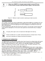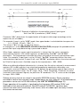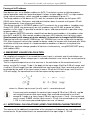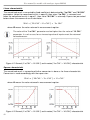
1
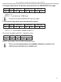
USER MANUAL for
module with analogue inputs
type:
PMI-8S
firmware version: 1.00 or higher
current inputs: PMI-8S-P
voltage inputs: PMI-8S-N
Read the user's manual carefully before starting to use the unit.
Producer reserves the right to implement changes without prior notice.
29.04.2009
V.1.06
User manual for module with analogue inputs PMI-8S
CONTENTS
1. BASIC REQUIREMENTS AND USER SAFETY ....................................................................................... 3
2. GENERAL CHARACTERISTICS.............................................................................................................. 3
3. TECHNICAL DATA .................................................................................................................................. 4
4. DEVICE INSTALLATION ......................................................................................................................... 5
4.1. UNPACKING .................................................................................................................................. 5
4.2. CONNECTION METHOD ............................................................................................................... 5
4.3. MAINTENANCE ............................................................................................................................. 7
5. PRINCIPLE OF OPERATION ................................................................................................................... 7
6. MEASURED VALUES CALCULATION.................................................................................................... 9
6.1. ADDITIONAL CALCULATIONS (USED CONVERSION CHARACTERISTIC) ................................ 9
6.2. EXAMPLES OF CALCULATIONS ................................................................................................ 12
7. THE MODBUS PROTOCOL HANDLING ............................................................................................... 15
7.1. LIST OF REGISTERS .................................................................................................................. 15
7.2. TRANSMISSION ERRORS DESCRIPTION................................................................................. 17
7.3. EXAMPLES OF QUERY/ANSWER FRAMES .............................................................................. 17
Explanation of symbols used in the manual:
- This symbol denotes especially important guidelines concerning the installation and
operation of the device. Not complying with the guidelines denoted by this symbol
may cause an accident, damage or equipment destruction.
IF THE DEVICE IS NOT USED ACCORDING TO THE MANUAL THE USER IS
RESPONSIBLE FOR POSSIBLE DAMAGES.
- This symbol denotes especially important characteristics of the unit. Read any
information regarding this symbol carefully
2
User manual for module with analogue inputs PMI-8S
1. BASIC REQUIREMENTS AND USER SAFETY
- The manufacturer is not responsible for any damages caused by
inappropriate installation, not maintaining the proper technical condition and
using the unit against its destination.
- Installation should be conducted by qualified personnel. During installation all
available safety requirements should be considered. The fitter is responsible for
executing the installation according to this manual, local safety and EMC
regulations.
- The unit must be properly set-up, according to the application. Incorrect
configuration can cause defective operation, which can lead to unit damage or an
accident.
- If in the case of a defect of unit operation there is a risk of a serious threat to
the safety of people or property additional, independent systems and
solutions to prevent such a threat must be used.
- Neighbouring and mating equipment must meet the requirements of appropriate
standards and regulations concerning safety and be equipped with adequate antiovervoltage and anti-interference filters.
- Do not attempt to disassemble, repair or modify the unit yourself. The unit
has no user serviceable parts. Units, in which a defect was stated must be
disconnected and submitted for repairs at an authorized service centre.
The unit is designed for operation in an industrial environment and must not
be used in a household environment or similar.
2. GENERAL CHARACTERISTICS
Module allows measurement of 8 analog channels (current or voltage, depending on version)
and makes them accessible via RS-485 interface. PMI-8S can be used as input block of
scattered measurement and visualization systems.
Standard Modbus RTU functions can be used for changing module settings (like address, baud
rate, measurement ranges etc.) and read measurement results or identification data.
3
User manual for module with analogue inputs PMI-8S
3. TECHNICAL DATA
Power supply voltage
16...24...30 VDC
External fuse (required)
T - type, max. 1 A
Current consumption
55 mA typically
Number of independent inputs
8
Inputs (depending on version)
current:
or voltage:
0÷20 mA; 4÷20 mA
0÷10 V; 2÷10 V; 0÷5 V; 1÷5 V;
Measurement accuracy
± 0.25 % ± one digit
Accepted prolonged inputs overload
20 %
Galvanic isolation
All inputs are galvanically isolated from module supply
and RS-485 interface
Communication interface
RS-485, 8N1 / Modbus RTU
Baud rate
1200 ÷ 115200 bit/sec
Number of modules in 1 network
maximum 128
Data memory
non-volatile memory, EEPROM type
Protection level
IP 20 (housing and connection clips)
Housing type
Housing dimensions (L x W x D)
DIN rail mounted (35 mm rail)
101 x 22.5 x 80 mm
Operating temperature
Storage temperature
Humidity
Altitude
0 °C to +50 °C
-10 °C to +70 °C
5 to 90 % no condensation
up to 2000 meters above sea level
Screws tightening max. torque
0.5 Nm
Max. connection leads diameter
2.5 mm
EMC
according to: PN-EN 61326
2
This is a class A unit. In housing or a similar area it can cause radio frequency
interference. In such cases the user can be requested to use appropriate
preventive measures.
4
User manual for module with analogue inputs PMI-8S
4. DEVICE INSTALLATION
The unit has been designed and manufactured in a way assuring a high level of user safety and
resistance to interference occurring in a typical industrial environment. In order to take full
advantage of these characteristics installation of the unit must be conducted correctly and
according to the local regulations.
- Read the basic safety requirements on page 3 prior to starting the installation.
- Ensure that the power supply network voltage corresponds to the nominal voltage
stated on the unit’s identification label.
- The load must correspond to the requirements listed in the technical data.
- All installation works must be conducted with a disconnected power supply.
4.1. UNPACKING
After removing the unit from the protective packaging, check for transportation damage. Any
transportation damage must be immediately reported to the carrier. Also, write down the unit
serial number on the housing and report the damage to the manufacturer.
Attached with the unit please find:
- user’s manual
- warranty
4.2. CONNECTION METHOD
Caution
- Installation should be conducted by qualified personnel. During installation all
available safety requirements should be considered. The fitter is responsible for
executing the installation according to this manual, local safety and EMC
regulations.
- Wiring must meet appropriate standards and local regulations and laws.
- In order to secure against accidental short circuit the connection cables must be
terminated with appropriate insulated cable tips.
- Tighten the clamping screws. The recommended tightening torque is 0.5 Nm.
Loose screws can cause fire or defective operation. Over tightening can lead to
damaging the connections inside the units and breaking the thread.
- In the case of the unit being fitted with separable clamps they should be inserted
into appropriate connectors in the unit, even if they are not used for any
connections.
- Unused clamps (marked as n.c.) must not be used for connecting any
connecting cables (e.g. as bridges), because this can cause damage to the
equipment or electric shock.
5
User manual for module with analogue inputs PMI-8S
Due to possible significant interference in industrial installations appropriate measures
assuring correct operation of the unit must be applied. To avoid the unit of improper
indications keep recommendations listed below.
-
Avoid common (parallel) leading of signal cables and transmission cables together
with power supply cables and cables controlling induction loads (e.g. contactors).
Such cables should cross at a right angle.
-
Contactor coils and induction loads should be equipped with anti-interference
protection systems, e.g. RC-type.
-
Use of screened signal cables is recommended. Signal cable screens should
be connected to the earthing only at one of the ends of the screened cable.
-
In the case of magnetically induced interference the use of twisted couples of signal
cables (so-called “spirals”) is recommended. The spiral (best if shielded) must be
used with RS-485 serial transmission connections.
-
In the case of interference from the power supply side the use of appropriate antiinterference filters is recommended. Bear in mind that the connection between the
filter and the unit should be as short as possible and the metal housing of the filter
must be connected to the earthing with largest possible surface. The cables
connected to the filter output must not run in parallel with cables with interference
(e.g. circuits controlling relays or contactors).
External powers supply must be connected to the module (+Uz, -Uz, typically 24 VDC) and two
wires RS-485 (A+, B-) communication interface. Inputs are placed on bottom side of the
module (see: Figure 4.1).
Figure 4.1. Terminals description
6
User manual for module with analogue inputs PMI-8S
●
●
When use of SMPS it is strongly recommended to connect PE wire.
All connections must be made while power supply is disconnected!
Figure 4.2. Method of cable insulation replacing and cable terminals
4.3. MAINTENANCE
The unit does not have any internal replaceable or adjustable components available to the user.
Pay attention to the ambient temperature in the room where the unit is operating. Excessively
high temperatures cause faster ageing of the internal components and shorten the fault-free
time of unit operation.
In cases where the unit gets dirty do not clean with solvents. For cleaning use warm water with
small amount of detergent or in the case of more significant contamination ethyl or isopropyl
alcohol.
Using any other agents can cause permanent damage to the housing.
Product marked with this symbol should not be placed in municipal waste. Please
check local regulations for disposal and electronic products.
5. PRINCIPLE OF OPERATION
The Module allows to measurement analog values from 8 current (or voltage) inputs with speed
rate about 10 Hz (every channel). Measurement results can be internally recalculated due to
one of available characteristics: linear, square or user definable multipoint (max.20 points
length). The expansion of nominal range is defined by “Lo r” and “Hi r” parameters. They
determine the permissible range of input signal (Figure 5.1).
The permissible range allow user to exceed the nominal range of input signal. If input signal
exceeds the permissible range (defined by “Lo r” and “Hi r”), appropriate bit of status register
(register 09h) will be set. This bit signalise exceeding of permissible measurement range.
The “Lo r” parameter is important if input is set to “4-20”, “1-5” or “2-10” mode only, and
determines lower border of the permissible range. If input is set to “0-20”, “0-5” or
“0-10” mode then lower border of the permissible range is always 0. For example if input is set
to “4-20” mode, then lower border is calculated due to expression:
Imin = 4 mA - 4 mA × “Lo r” %.
The “Lo r” value can be set from 0 to 99.9 %.
7
User manual for module with analogue inputs PMI-8S
Figure 5.1 Example of definition of permissible range of input signal “Lo r” and “Hi r” parameters (“4-20” mode)
Parameter “Hi r” determines the upper border of the permissible range accordingly to the
expression (for all modes).
For example if input is set to “4-20” mode, then upper border is calculated due to expression:
Imax = 20 mA + 20 mA × “Hi r” %.
The value of “Hi r” can be set from 0 to 19.9 %.
In example no 1 of the MEASURED VALUES CALCULATION paragraph the procedure of the
permissible input range determining is presented in details.
When linear, square or square root characteristic is chosen then the values returned in
measurement registers (01h to 08h registers) are defined by “Lo CAL” and “Hi CAL”
parameters. These parameters describe the values returned for minimum and maximum input
value. For example, if input type is set to 4-20 mA, “Lo CAL” parameter defines the value
returned when input current is equal 4 mA, and “Hi CAL” parameter defines the value returned
for 20 mA of input current. Available range for these parameters: -999 ÷ 9999.
When user defined multipoint characteristic is chosen then the values returned in measurement
registers (01h to 08h registers) are calculated according to coordinates defined by user
(X, Y points, maximal 20 points). Coordinate “X” defines the percentage ratio of input value to
selected measurement range. The “X” range: -99.9 ÷ 199.9. Coordinate “Y” defines the value
(returned in measurement register) for particular “X” coordinate. The “Y” value can be changed
in range: -999 ÷ 9999.
Settings of every channel are stored in nonvolatile EEPROM memory. Device signalizes
overload of nominal measurement range (independently for every channel). All available device
parameters can be set via RS-485 interface (see: LIST OF REGISTERS page 15).
Proper operation of the module is signalized by flashing green LED marked “RUN” and
localized on front panel of the device. Red LED marked “Tx/ERROR” signalizes data
transmission over serial interface by short flashes, when this diode lights constantly it means
that some error occurred.
8
User manual for module with analogue inputs PMI-8S
Forcing of 0xFF address
New devices has set to Modbus addresses 0xFE. To enhance system installation process
special operation mode has been developed. It allows to force address 0xFF in single module
using internal momentary switch mounted on module mainboard (Figure 4.1).
To change address of the device to FFh, wait for a moment after power up until green LED
(RUN) starts flashes. Next press and hold push-button about 4 seconds until green LED will
lights permanently, then release push-button.
The device changes its MODBUS address to FFh and waits for a new address (readdressing).
Green LED (RUN) stay permanently on until readdressing via RS-485, or power off. While
module is in this state it is possible to control its inputs, and communication is possible using
temporal address FFh.
At this moment MASTER controller should find new device and readdress it (to address other
than 0xFF and 0xFE). After remote readdressing green LED indicator starts to flashes again.
Simultaneously with change of device address, its baud rate is changed to 9600 bit/sec.
Required transmission speed (1200 bit/sec. to 115200 bit/sec.) can be set by write to register
22h. After change of transmission speed the device sends the answer with new baud rate. While
installation of the new network it is recommended to readdress all devices using baud rate
9600 bit/sec, and next change speed of all devices simultaneously, using BROADCAST query
(with address 00h).
6. MEASURED VALUES CALCULATION
For simplicity of examples it's assumed that current input is selected, and all calculations are
related to this input. When voltage input is selected calculations are similar (be sure of particular
ranges and units).
The first step to compute the result of measure is the calculation of the normalized result (it
means result of 0-1 range). To do it, the begin of the input range (0 mA for 0-20 mA range, and
4 mA for 4-20 mA range) must be subtracted from measured value. Next, received result must
be divided by the width of the input range (it means 20 mA for 0-20 mA range, and 16 mA for
4-20 mA range). So normalized result can be expressed by expressions:
where Iinp. Means input current (in mA), and In – normalized result.
If measured value exceeds the nominal input range (0-20 mA or 4-20 mA), and do
not exceed the permissible input range, then received normalized In result will
exceed 0-1 range, e.g. input range 4-20 mA, input current = 3 mA – the normalized
result is equal -0.0625, and for input current = 22 mA, the normalized result is equal
1.125. In such cases presented expressions are still correct.
6.1. ADDITIONAL CALCULATIONS (USED CONVERSION CHARACTERISTIC)
The manner of the additional computation of the returned result depends on selected conversion
characteristic. All presented charts are connected with the input range 4 - 20 mA.
9
User manual for module with analogue inputs PMI-8S
Linear characteristic
The normalized result is converted by fixed coefficients determined by “Lo CAL” and “Hi CAL”
parameters (when the normalized results is equal 0, then value “Lo CAL” is returned, and
when the normalized results is equal 1, then value “Hi CAL” is returned). Expression presented
below shows the manner of result calculation:
W=In × (“Hi CAL”−“Lo CAL”) + “Lo CAL”
where W means the value returned in measurement register.
The value of the “Lo CAL” parameter can be higher than the value of “Hi CAL”
parameter. In such a case, for an increasing value of input current the returned
value decreases.
Figure. 6.1 Normal (“Lo CAL” < “Hi CAL”) and inverted (“Lo CAL” > “Hi CAL”) characteristic
Square characteristic
The normalized result is squared and further conversion is done as for linear characteristic.
Conversion is made accordingly with the expression:
W=In 2 × (“Hi CAL”−“Lo CAL”) + “Lo CAL”
where W means the value returned in measurement register.
Figure. 6.2 Normal (“Lo CAL” < “Hi CAL”) and inverted (“Lo CAL” > “Hi CAL”) characteristic
10
User manual for module with analogue inputs PMI-8S
Square root characteristic
The normalized result is rooted and further conversion is done as for linear characteristic.
Conversion is made accordingly with the expression:
where W means the value returned in measurement register.
Showed above expression is not valid when normalized result is negative. It is
possible for 4-20 mode only. In this case (In<0) the returned result is equal “Lo CAL”
(see graphs below).
Figure. 6.3 Normal (“Lo CAL” < “Hi CAL”) and inverted (“Lo CAL” > “Hi CAL”) characteristic
User defined characteristic
User defined characteristic is defined as set of X-Y points. Number of the points is variable and
may be set from 2 to 20 points which make linear segments (see graph and see LIST OF
REGISTERS).
Due to the normalized result In, the device computes specific segment, e.g. for characteristic
from figure below, and In = 0.65 the segment between points X = “50.0.” and X = “70.0.” will be
chosen.
Let's mark those points as PL (point low) i PH (point high) - in this example PL= “50.0,” and
PH = “70.0.”, and the normalized result In for the point PL as Ip (in this example Ip = In(PL) = 0.5).
The returned result is calculated accordingly to the expression:
where Y(PH), X(PH), Y(PL), X(PL) mean values of X and Y coordinates of PH i PL points.
If the normalized result exceeds the user defined characteristic values, then specific
utmost segment, defined by two next points, is used for calculations. If characteristic
from figure below is used, and if In>1 then segment defined by points X(PL) = “90.0.”,
X(PH) = “100.0.” will be used.
11
User manual for module with analogue inputs PMI-8S
Figure. 6.4 Example of user defined characteristic
6.2. EXAMPLES OF CALCULATIONS
Example 1: Selection of the permissible input range (“4-20” mode)
If in “4-20” mode the user sets “Lo r” = 20.0 % and “Hi r” = 10.0 %, then permissible input
currents range will be equal: 3.2 mA ÷ 22 mA. Lower border of the range is the result of
calculations: 4 mA - 4 mA × 20 %, and the higher: 20 mA + 20 mA × 10 %.
Example 2: The normalized In result calculation
Let the input mode = 4-20 mA. The normalized In result is calculated accordingly to the
expression on page 9, so if Iin = 10 mA then 10 mA - 4 mA = 6 mA, and this result should be
divided by the width of input range (16 mA). Finally the normalized result: In = 6/16 = 0.375.
In case when input current exceeds nominal measurement range, calculations are similar. For
example if input current is equal 2.5 mA then In = (2.5 - 4)/16 ≅ -0.0938, and if input current is
equal 20.5 mA then In = (20.5 - 4)/16 ≅ 1.0313.
Example 3: The linear characteristic
Let the input mode = 4-20 mA, and parameters “Lo CAL” and “Hi CAL” equal to 300 and 1200
respectively. The calculations will be done for there different input currents from example 2.
12
User manual for module with analogue inputs PMI-8S
a) Iin =10 mA and In = 0.375
Accordingly to expression on page 10 for linear characteristic:
0.375 × [1200 - 300] ≅ 337 and next, the “Lo CAL” value is added to the result , so the
returned value:
W ≅ 337 + 300 = 637
b) Iin = 2.5 mA and In = -0.0938.
W ≅ 216.
c) Iin = 20.5 mA and In = 1.0313.
W ≅ 1228.
Example 4: The square characteristic
Let the input mode = 4-20 mA, and parameters “Lo CAL” and “Hi CAL” equal to 300 and 1200
respectively. The calculations will be done for there different input currents from example 2.
a) Iin =10 mA and In = 0.375
2
Accordingly to expression on page 10 for linear characteristic: (0.375) × [1200 - 300] ≅ 127.
and next, the “Lo CAL” value is added to the result , so the returned value:
W ≅ 127 + 300 = 427
b) Iin = 2.5 mA and In = -0.0938.
W ≅ 308.
c) Iin = 20.5 mA and In = 1.0313.
W ≅ 1257.
Example 5: The square root characteristic
Let the input mode = 4-20 mA, and parameters “Lo CAL” and “Hi CAL” equal to 300 and 1200
respectively. The calculations will be done for there different input currents from example 2.
a) Iin =10 mA and In = 0.375
Accordingly to expression on page 11 for linear characteristic:
√0.375 × [1200 - 300] ≅ 551.
and next, the “Lo CAL” value is added to the result , so the returned value:
W ≅ 551 + 300 = 851
b) Iin = 2.5 mA and In = -0.0938, normalized result is negative, so the returned value is
equal to “Lo CAL” parameter: W ≅ “Lo CAL” = 300.
c) Iin = 20.5 mA and In = 1.0313.
W ≅ 1214.
13
User manual for module with analogue inputs PMI-8S
Example 6: The user defined characteristic
Let the input mode = 4-20 mA, and the user selected the 10 segment characteristic. To do this it
is necessary to enter X and Y coordinates of 11 points (see LIST OF REGISTERS).
The calculations will be done for three different input currents from example 2, so in calculations
some of the segments will be used only.
Let the following points will be given:
X1 = “00.0.”, Y1 = “10.0”
X2= “10.0.”, Y2 = “20.0”
....
X6 = “30.0.”, Y6 = “30.0”
X7 = “40.0.”, Y7 = “80.0”
....
X10 = “90.0.”, Y10 = “900.0”
X11 = “100.0.”, Y11 = “820.0”
Additionally all other points must to be defined and stored in the device memory.
a) Iin =10 mA and In = 0,375
The segment defined by X6 = “30.0.” i X7 = “40.0.” for this In will be selected. Accordingly to
expressions given for user defined characteristic (see page 11) X6(PL) = 30, Y6(PL) = 30,
X7(PH) = 40, Y7(PH) = 80 and Ip = 0,3 , the returned value :
b) Iin = 2.5 mA and In = -0.0938, because of the normalized In value is lower than 0, the segment
defined by X1 and X2 will be selected. X1(PL) = 0, Y1(PL) = 10, X2(PH) = 10,
Y2(PH) = 20 and Ip = 0. For these values the returned value W ≅ 1.
b) Iin = 20.5 mA and In = 1.0313. , because of the normalized In value is higher than 1, the
segment defined by X10 and X11 will be selected, and X10(PL) = 90, Y10(PL) = 900,
X11(PH) = 100, Y11(PH) = 820 and Ip = 0.9 for these values the returned value W ≅ 795.
14
User manual for module with analogue inputs PMI-8S
7. THE MODBUS PROTOCOL HANDLING
Transmission parameters: 1 start bit, 8 data bits, 1 stop bit, no parity control
Baud rate:
selectable from: 1200 to 115200 bits/sec
Transmission protocol:
MODBUS RTU compatible
The device parameters and display value are available via RS-485 interface, as HOLDING-type
registers (numeric values are given in U2 code) of Modbus RTU protocol. The registers
(or groups of the registers) can be read by 03h function, and wrote by 06h (single registers) or
10h (group of the registers) accordingly to Modbus RTU specification. Maximum group size for
03h and 10h functions cannot exceeds 16 registers (for single frame).
The device interprets the broadcast messages, but then do not sends the answers.
7.1. LIST OF REGISTERS
Register
Write
Range
Register description
01h
No
-10000÷ 10000
Result of channel 1
02h
No
-10000÷ 10000
Result of channel 2
03h
No
-10000÷ 10000
Result of channel 3
04h
No
-10000÷ 10000
Result of channel 4
05h
No
-10000÷ 10000
Result of channel 5
06h
No
-10000÷ 10000
Result of channel 6
07h
No
-10000÷ 10000
Result of channel 7
08h
No
-10000÷ 10000
Result of channel 8
09h
No
0000h - FFFFh
20h1
Yes
1 ÷ FFh
Device address. New devices has default address = FEh
Status register for channels 1 - 8
21h
No
209Ah
Device identification code (ID)
22h2
Yes
0÷7
Baudrate: 0 - 1200 baud; 1 - 2400 baud; 2 - 4800 baud;
3 - 9600 baud; 4 - 19200 baud; 5 - 38400 baud;
6 - 57600 baud; 7 - 115200 baud
23h3
Yes
0÷1
Permission to write registers via RS-485 interface:
0 - write denied ; 1 - write allowed
25h
Yes
0÷5
Additional response delay: 0 - no additional delay;
1 - 10 characters delay; 2 - 20 characters delay;
3 - 50 characters delay; 4 - 100 characters delay;
5 - 200 characters delay
27h
Yes
0 ÷ 99
Maximum delay between received frames:
0 - no delay checking;
1 ÷ 99 - maximum delay expressed in seconds
15
User manual for module with analogue inputs PMI-8S
Register
Write
Range
Register description
28h ÷ 2Fh
Channel 1 parameters block
30h ÷ 37h
Channel 2 parameters block
38h ÷ 3Fh
Channel 3 parameters block
40h ÷ 47h
Channel 4 parameters block
48h ÷ 4Fh
Channel 5 parameters block
50h ÷ 57h
Channel 6 parameters block
58h ÷ 5Fh
Channel 7 parameters block
60h ÷ 67h
Channel 8 parameters block
1
2
3
4
See below
70h4
Yes
-999 ÷ 1999
The value of “X” coordinate of point no. 1 of the user defined
characteristic, expressed in 0.1 %
71h4
Yes
-10000÷ 10000
The value of “Y” coordinate of point no. 1 of the user defined
characteristic, no decimal point included
72h4 ÷ 95h4
Further pairs of “X” – “Y” coordinates of points no. 2 ÷ 19 of
the user defined characteristic
96h4
Yes
-999 ÷ 1999
The value of “X” coordinate of point no. 20 of the user defined
characteristic, expressed in 0.1 %
97h4
Yes
-10000÷ 10000
The value of “Y” coordinate of point no. 20 of the user defined
characteristic, no decimal point included
- after writing to register no 20h the device responds witch an “old” address in the message.
- after writing to register no 22h the device responds with the new baud rate.
- the value of this parameter is also connected to write to this register, so it is possible to block a writes, but
impossible to unblock writes via RS-485 interface, The unblocking of the writes is possible by device reset only
(see “Forcing of 0xFF address”, page 9).
- the pairs of “X -Y” coordinates may be defined for any free point. The pair is “free” (it means that particular point
is not defined) if “X” coordinate of this point is equal 8000h. After writing both X and Y coordinate the point is
defined and used in calculation of result. The coordinates of any point can be changed at any time.
Content of channel parameters block:
Relative
address
16
Write
Range
Description
Measurement range:
0 - 0-20 mA (current version ) or 0-10 V (voltage version);
0 ÷ 1 (current version)
1 - 4-20 mA (current version ) or 2-10 V (voltage version);
0 ÷ 3 (voltage version)
2 - 0-5 V (voltage version only);
3 - 1-5 V (voltage version only);
+0
Yes
+1
Yes
0÷3
Channel characteristic:
0 - linear ; 1 - square; 2 - square root; 3 - user defined
+2
Yes
0÷5
Digital filter (exponential):
0 – no filtration; 5 – maximum filtration.
+3
Yes
-10000 ÷ 10000
Parameter “Lo CAL”
This value is returned as Channel Result when input
current is equal to bottom border of the selected range
User manual for module with analogue inputs PMI-8S
Description
Relative
address
Write
Range
+4
Yes
-10000 ÷ 10000
+5
Yes
0÷ 999
Parameter “Lo r”, expressed by 0.1 %
Percentage extension of measurement range below its
bottom border
+6
Yes
0 ÷ 200
Parameter “Hi r” , expressed by 0.1 %
Percentage extension of measurement range over its
upper border
Parameter “Hi CAL”
This value is returned as Channel Result when input
current is equal to upper border of the selected range
It is possible to read up to 12 registers at once (see example no. 1).
Content of status register (no. 09h)
Bit no.
15, … , 8
7, … , 0
function
H8, … , H1
L8, … , L1
Bits H1 to H8 mean overflow of measurement range of particular channels
Bits L1 to L8 mean underflow of measurement range of particular channels
7.2. TRANSMISSION ERRORS DESCRIPTION
If an error occurs while write or read of single register, then the device sends an error code
according to Modbus RTU specifications.
Error codes:
01h - illegal function (only functions 03h and 06h are available)
02h - illegal register address
03h - illegal data value
7.3. EXAMPLES OF QUERY/ANSWER FRAMES
Examples apply for device with address 1. All values are represent hexadecimal.
Field description:
ADDR
Device address on modbus network
FUNC
Function code
REG H,L
Starting address (address of first register to read/write, Hi and Lo byte)
COUNT H,L
No. of registers to read/write (Hi and Lo byte)
BYTE C
Data byte count in answer frame
DATA H,L
Data byte (Hi and Lo byte)
CRC L,H
CRC error check (Hi and Lo byte)
17
User manual for module with analogue inputs PMI-8S
1. Read of the registers 01h ÷ 09h in one message (example of reading a number of
registries in one frame):
ADDR
FUNC
01
03
REG H,L
00
DATA
01
00
CRC L,H
09
D4
0C
a) The answer:
Interpretation of the answer:
Channels 1, 2, 3 results respectively: 150, -5000, 2020 (negative numbers U2 coded). All other
channels give 0. Status register signalizes overflow in channel 3.
2. Read of device ID code
ADDR
FUNC
REG H,L
01
03
00
ADDR
FUNC
BYTE C
01
03
02
COUNT H,L
21
00
CRC L,H
01
D4
00
The answer:
DATA H,L
20
CRC L,H
9A
21
EF
DATA - identification code (209Ah)
3. Change of the device address from 1 to 2 (write to reg. 20h)
ADDR
FUNC
01
06
REG H,L
00
20
DATA H,L
00
02
CRC L,H
09
C1
DATA H - 0
DATA L - new device address (2)
The answer (the same as the message):
18
ADDR
FUNC
01
06
REG H,L
00
20
DATA H,L
00
02
CRC L,H
09
C1
User manual for module with analogue inputs PMI-8S
4. Change of baud rate of all devices connected to the net (BROADCAST message).
ADDR
FUNC
00
06
REG H,L
00
COUNT H,L
22
00
04
CRC L,H
29
D2
DATA H - 0
DATA L - 4, new baud rate 19200 baud
Device do not reply to BROADCAST-type messages.
5. Try to write illegal data value into baud rate register
ADDR
FUNC
01
06
REG H,L
00
DATA H,L
22
00
09
CRC L,H
E9
C6
DATA L = 9 - value exceeds allowable range (0÷7)
The answer (exception code 03h - illegal data value):
ADDR
FUNC
ERR
01
86
03
CRC L,H
02
61
ERROR - error code (in this case 03h, illegal data value)
There is no full implementation of the Modbus Protocol in the device. The
functions presented above are available only.
19
User manual for module with analogue inputs PMI-8S
BD|Sensors GmbH
BD-Sensors-Straße 1
95199 Thierstein, Germany
Telefon +49 (0) 9235 / 9811 - 2099
Telefax +49 (0) 9235 / 9811 - 860
e-mail: [email protected]
www.bdsimex.de
20
04-2010