1
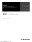
Professional
UHF Wireless Systems
ATW-A54P UHF Powered Dipole Antennas, 541-567 MHz
ATW-A64P UHF Powered Dipole Antennas, 655-681 MHz
Installation and Operation
UHF Powered Dipole Antennas
Installation and Operation
Warning: To prevent fire or shock hazard, do
not expose this appliance to rain or moisture.
Attention: Pour prévenir feu ou choc
électrique, ne pas exposé l’appareil à la pluie
ou à l’humidité.
CAUTION! The circuits and wiring inside the antennas are
adjusted for optimum performance. Do not attempt to alter
circuitry or wiring to affect output. To do so will void the
warranty and may cause improper operation or system
degradation.
This device complies with part 15 of the FCC Rules. Operation is
subject to the condition that this device does not cause harmful
interference.
This device complies with INDUSTRY CANADA R.S.S. 210, en
conformité avec IC: RSS-210/CNR210. Operation is subject to
the following conditions: 1) This device may not cause harmful
interference and 2) this device must accept any interference
received, including interference which may cause undesired
operation.
CAUTION! To prevent electrical shock and possible damage
to the antenna, use caution when connecting 12V power from
the receiver or antenna distribution system.
Antenna Location & Orientation
Introduction
Audio-Technica ATW-A54P and ATW-A64P powered dipole
antennas provide effective and reliable signal pickup for UHF
wireless systems. Supplied in pairs, these antennas are
intended to improve performance of diversity wireless receiving
systems with dual antenna inputs.
Designed for temporary or permanent installation, these
antennas are powered by 12 volts DC provided on the antenna
cable by the associated receiver or antenna distribution system.
Power is required for antenna operation; an indicator on each
housing lights when power is applied. An internal gain-setting
switch permits selection of +10 or +4 dB operation, to
compensate for cable losses or other operating conditions.
The ATW-A54P and ATW-A64P are designed for particular UHF
frequency bands:
ATW-A54P: 541-567 MHz (TV channels 25-30)
For best operation, the antennas should be mounted on a lineof-sight to the most likely location(s) of the transmitter, while
also considering the shortest length of cable required to reach
the receiver. Usually this means placing the antennas well up
on a wall, above head height, and above the level at which they
might be hit or obstructed. The two antenna housings should
be mounted at the same height, oriented vertically, and with
at least 12" (30 cm) between them (Fig. A). As much as
possible, keep the antennas away from noise sources such as
digital equipment, motors and neon lights, as well as away
from large metal objects.
When determining a location for a permanent installation, it is
often a good idea to try the selected location temporarily with
the wireless system (and any other RF or computer equipment)
in full operation to confirm optimum system performance.
Fig. A
ATW-A64P: 655-681 MHz (TV channels 44-49)
The ATW-A54P and ATW-A64P are designed for interior use.
Do not install them outdoors, or where condensation or
extremely high humidity is present. Both models permit several
means of mounting for temporary use or permanent installation.
Included AT8667 brackets with BNC connectors and 5/8"-27
threaded mounts permit convenient use with conventional
microphone stands or other 5/8"-27 threaded fixtures. The
antennas may also be permanently secured directly to walls or
other vertical structures, or they may be attached to single-gang
electrical boxes. The RF cables may be totally hidden by exiting
behind the antenna housings, or they may exit through an
opening at the bottom of each housing to be routed along the
wall or mounting structure.
Audio-Technica offers several optional RF extension cables: A
12' (3.6 m) RG58-type, plus 25', 50' and 100' (7.6, 15.2 and
30.5 m) RG8-type cables. All have BNC-to-BNC connectors.
12" minimum
Transmitter
Location
t
gh
-si
f
o
eLin
Locate antennas away
from mirrors or other
large metallic surfaces
Unobstructed
position,
high on wall
Antenna Mounting
The attractive molded housings are easily removable for
installation or adjustment. Simply remove the two silver-color
screws located at the rear of each housing and gently pull
the housing forward, away from the black metal rear plate
(Fig. B).
Internal Connections
Cable Selection
Screw-terminal connections in the antennas are designed for
use with RG58-type or RG8-type RF transmission cables, or
with Asian RF cable types 3D or 5D. Make certain the cable
selected is intended for UHF operation and has a full braided
copper shield, not just a metalized foil shield. For runs of 25'
(8 m) or more, a low-loss cable such as RG8 should be used.
For portable or temporary use, install the included AT8667
brackets with BNC connectors and 5/8"-27 threaded mounts.
Attach each bracket to an antenna using two small, black
machine screws (included). Direct the screws from inside the
antenna’s rear plate through the inner pair of small holes, and
screw them into the tapped holes in the bracket. Prepare the
free ends of the short cables as shown in Figure C.
Cable Stripping
RG58: Observing the dimensions in Figure C, remove a section
of the outer jacket and a portion of the inner coax insulation,
being careful not to cut or nick the shield or center wires (C1).
For permanent installation, the antennas may be attached to a
wall or other vertical support with appropriate fasteners. They
also may be mounted to a single-gang electrical box, via the
outer pair of small holes on the rear plate (using #6-32 screws,
not included). When installing, position the units so the gain
switches and screw terminals face to the right.
The PC board may be removed for safety or convenience while
installing the metal rear plate, if desired. Simply remove the
two screws indicated in Figure B. When re-mounting the PC
board, note that the board goes on the “outside” of the rear
plate’s mounting ears.
Fig. B
Gain
Switch
Hi
Power
Indicator
Center
Conductor
Cable
Clamp
PC
Board
Mounting
Screws
Cable Clamp
Screw Locations
Housing Screw
RG8: When using RG8-type cable, more jacket material needs
to be removed and partially replaced with shrink tubing. When
installing the tubing, heat the tubing and cable only enough to
shrink the tubing. Allow the cable to cool fully before manipulating it further. The drawings in Figures D and E are actualsize; the shrink-tubing indications show the actual length of
pieces to be cut, and their correct placement on the cable. Cut
the required pieces from the included shrink tubing.
RG8 / Rear exit: When connecting antennas from the rear, follow the cable-stripping dimensions in Figure D. Then install a 1"long (25 mm) piece of shrink tubing as indicated. Remove the
cable clamp and carefully insert the cable end into position
through the rear plate.
Rear Plate
Lo
Antenna
Housing
Note: If the cable jacket’s outer diameter is less than 7/32"
(0.21", 5.3 mm), wrap the jacket with electrical tape to build up
its diameter before folding back the braid over the jacket (C2).
Trim the shield wires to 9/16" (15 mm).
RG8 / Bottom exit: When connecting antennas through the
opening in the antenna housing, follow the cable-stripping
dimensions in Figure E. Then install a 2.5"-long (63 mm) piece
of shrink tubing as indicated. Remove the cable clamp and
carefully position the cable to exit at the bottom edge of the
rear plate. The end of the cable’s jacket must be located about
1
/4" (6 mm) beyond the end of the rear plate to clear the bottom
of the housing. Then secure the clamp and center conductor.
Fig. D RG8 Cable - Rear Exit
Fig. C RG58, 3D, 5D Cables
Shrink Tubing
1" (25 mm)
(C1)
1.22" (31 mm)
0.79"
(20 mm)
0.59"
0.2"
(5 mm) (15 mm)
2.00" (51 mm)
(C2)
Fig. E RG8 Cable - Bottom Exit
0.59"
(15 mm)
0.59"
(15 mm)
Shrink Tubing
2.5" (63 mm)
0.2"
(5 mm)
2.68" (68 mm)
3.46" (88 mm)
0.2"
0.59"
(5 mm) (15 mm)
Cable Connections
Refer to Figure F (cable rear exit) or Figure G (bottom exit) for
connecting positions. When using a screwdriver on the antenna
terminals, always support the PC board.
Center Conductor: Wrap the center conductor(s) clockwise
around its screw and tighten snugly. (If using RG8, it is good
practice to bend its center conductors using pliers, not force
them around the screw terminal.)
Shield: It’s most effective to remove the cable clamp entirely,
properly position the shield portion of the cable, and then carefully reinstall the cable clamp over the shield. Make certain that
the shield (and cable) are firmly clamped, and that no shield
wires are loose or touching the center conductor.
Especially when using RG8 or other large, stiff cable, it’s a good
idea to provide some form of clamping of the cable near the
antenna’s cable entrance for strain relief.
Fig. F Rear Cable Exit
Antenna
Housing
Setting Gain
The gain switch on the PC board is intended only to compensate for signal lost in the antenna cable. Using "extra" gain is not
necessarily better! Observe the following chart for proper gain
switch setting:
Gain Setting
RG58-Type Cable
RG8-Type Cable
Hi (+10 dB)
20-50' (6-15 m)
50-150' (15-50 m)
Lo (+4 dB)
Up to 20' (6 m)
Up to 50' (15 m)
Both antennas in a diversity system should be set to the same
gain position. Other than setting the gain switches, do not
make any adjustments to the circuitry.
After stripping the cables, making cable connections and setting
gain, replace the antenna housings. When re-installing the
housing, be careful to avoid hitting the clear plastic "light pipe"
for the LED power indicator. Once the housings are secured
with the silver screws, connect the antenna cables to the
diversity receiver or antenna distribution system and turn on the
system. Then check for power indications at the antennas and
proper operation of the overall wireless system.
PC Board
Specifications
Rear Plate
Housing
Mounting
Antenna Type
Operating Frequencies
ATW-A54P
ATW-A64P
Output Impedance
Nominal Amplifier Gain
Power Required
Dimensions
Weight
Accessories Furnished
Fig. G Bottom Cable Exit
Half-wavelength dipole with RF amplifier
541-567 MHz
655-681 MHz
50 ohms
+10 dB (Hi), +4 dB (Lo),
switch selected
+12V DC on RF cable center conductor,
14 mA per antenna
2.44" (62 mm) W x 5.51" (140 mm) H x
5.91" (150 mm) D
9.7 oz (275 g) each
2 AT8667 mounting brackets; shrink
tubing (for use with RG8-type cable);
4 each of wood screws, 3.0 mm and
3.5 mm machine screws
Antenna
Housing
One-Year Limited Warranty
PC Board
Rear Plate
Housing
Mounting
Cable Exit
Audio-Technica professional wireless systems purchased in the U.S.A. are warranted
for one year from date of purchase by Audio-Technica U.S., Inc. ( A.T.U.S.) to be free of
defects in materials and workmanship. In event of such defect, product will be
repaired promptly without charge or, at our option, replaced with a new product of
equal or superior value if delivered to A.T.U.S. or an Authorized Service Center, prepaid, together with the sales slip or other proof of purchase date. Prior approval
from A.T.U.S. is required for return. This warranty excludes defects due to normal
wear, abuse, shipping damage, or failure to use product in accordance with the
instructions. This warranty is void in the event of unauthorized repair or modification,
or removal or defacing of the product labeling.
For return approval and shipping information, contact the Service Dept.,
Audio-Technica U.S., Inc., 1221 Commerce Drive, Stow, Ohio 44224.
Except to the extent precluded by applicable state law, A.T.U.S. will have no liability for any consequential, incidental, or special damages; any warranty of merchantability or fitness for particular purpose expires when this warranty
expires.
This warranty gives you specific legal rights, and you may have other rights which
vary from state to state.
Outside the U.S.A., please contact your local dealer for warranty details.
Audio-Technica U.S., Inc., 1221 Commerce Drive, Stow, Ohio 44224 330/686-2600 www.audio-technica.com
P51725 P#232303280 ©2004 Audio-Technica U.S., Inc. Printed in Japan